logo资料库

PCI-to-PCI Bridge Architecture Specification Rev1.2.pdf

第1页 / 共150页
第2页 / 共150页
第3页 / 共150页
第4页 / 共150页
第5页 / 共150页
第6页 / 共150页
第7页 / 共150页
第8页 / 共150页
资料共150页,剩余部分请下载后查看
Preface
Scope
Related Documents
1. Introduction
1.1. Goals and Non-Goals of This Specification
1.2. Overview and Terminology
2. Bridge Requirements
2.1. Summary of Key Requirements
2.2. Capabilities Not Supported
2.3. Optional Capabilities
3. Configuration
3.1. Overview of Hierarchical Configuration
3.1.1. Type 0 Configuration Transaction Support
3.1.2. Type 1 Configuration Transaction Support
3.1.2.1. Primary Interface
3.1.2.1.1. Type 1 to Type 0 Conversion
3.1.2.1.2. Type 1 to Type 1 Forwarding
3.1.2.1.3. Type 1 to Special Cycle Conversion
3.1.2.2. Secondary Interface
3.1.2.2.1. Type 1 to Type 1 Forwarding
3.1.2.2.2. Type 1 to Special Cycle Conversion
3.2. PCI-to-PCI Bridge Configuration Space Header Format
3.2.1. Accessing Reserved Registers
3.2.2. Accessing Reserved Bit Fields
3.2.3. Reset Events
3.2.4. Common Format Configuration Registers
3.2.4.1. Vendor ID Register
3.2.4.2. Device ID Register
3.2.4.3. Command Register
3.2.4.4. Status Register
3.2.4.5. Revision ID Register
3.2.4.6. Class Code Register
3.2.4.7. Cacheline Size Register
3.2.4.8. Latency Timer Register
3.2.4.9. Header Type Register
3.2.4.10. BIST Register
3.2.5. Bridge Specific Configuration Registers
3.2.5.1. Base Address Registers
3.2.5.1.1. Memory Base Address Register Format
3.2.5.1.2. I/O Base Address Register Format
3.2.5.2. Primary Bus Number Register
3.2.5.3. Secondary Bus Number Register
3.2.5.4. Subordinate Bus Number Register
3.2.5.5. Secondary Latency Timer Register
3.2.5.6. I/O Base Register and I/O Limit Register
3.2.5.7. Secondary Status Register
3.2.5.8. Memory Base Register and Memory Limit
Register
3.2.5.9. Prefetchable Memory Base Register and
Prefetchable Memory Limit Register
3.2.5.10. Prefetchable Base Upper 32 Bits and
Prefetchable Limit Upper 32 Bits Registers
3.2.5.11. I/O Base Upper 16 Bits and I/O Limit Upper 16
Bits Registers
3.2.5.12. Capabilities Pointer
3.2.5.13. Subsystem ID and Subsystem Vendor ID
3.2.5.14. Reserved Registers at 35h, 36h, and 37h
3.2.5.15. Expansion ROM Base Address Register
3.2.5.16. Interrupt Line Register
3.2.5.17. Interrupt Pin Register
3.2.5.18. Bridge Control Register
3.2.6. Slot Numbering Capabilities List Item
3.2.6.1. Slot Numbering Capabilities ID
3.2.6.2. Pointer to Next ID
3.2.6.3. Add-in Card Slot Register
3.2.6.4. Chassis Number Register
4. Address Decoding
4.1. Address Ranges
4.2. I/O
4.2.1. ISA Mode
4.3. Memory Mapped I/O
4.4. Prefetchable Memory
4.4.1. 64-bit Addressing
4.4.2. 64-bit Address Decoding of Prefetchable Memory
4.4.2.1. Below the 4-GB Boundary
4.4.2.2. Above the 4-GB Boundary
4.4.2.3. Across the 4-GB Boundary
4.5. VGA Support
4.5.1. VGA Compatible Addressing
4.5.2. VGA Palette Snooping
4.6. Subtractive Decode Support
5. Buffer Management
5.1. Prefetching Read Data
5.2. Posting Write Data
5.2.1. Memory Write and Invalidate Usage
5.2.1.1. Forwarding Memory Write and Invalidate
Transactions
5.2.1.2. Promoting Memory Write Transactions
5.2.1.3. Combining Memory Write Transactions
5.2.1.4. Memory Write and Invalidate Disconnects
5.2.1.4.1. Master Disconnected by the Bridge
5.2.1.4.2. Bridge Disconnected by the Target
5.3. Delayed Transactions
5.3.1. Discarding a Delayed Request
5.3.2. Discarding a Delayed Completion
5.4. Exclusive Access Transactions
5.4.1. Delayed Lock-Request Error
5.4.2. Normal Completion
5.5. Ordering Requirements
5.5.1. Summary of PCI Ordering Requirements
5.5.1.1. General Requirements
5.5.1.2. Delayed Transaction Requirements
5.5.2. Ordering of Requests
5.5.3. Ordering of Delayed Transactions
5.5.4. Transactions That Have No Ordering Constraints
5.5.5. Delayed Transactions and LOCK#
5.5.6. Error Conditions
5.5.7. Illustrations of the Use of the Ordering Rules
5.6. Special Design Considerations
5.6.1. Read Starvation
5.6.2. Stale Data
5.6.3. Deadlocks
5.7. Combining Separate Writes Into a Single Burst Transaction
5.8. Merging Separate Writes Into a Single Transaction
5.9. Collapsing of Writes
6. Error Support
6.1. Introduction
6.2. Parity Errors
6.2.1. Address Parity Errors
6.2.2. Read Data Parity Errors
6.2.2.1. Target Completion Error
6.2.2.2. Master Completion Error
6.2.3. Non-Posted Write Data Parity Errors
6.2.3.1. Master Request Error
6.2.3.2. Target Completion Error
6.2.3.3. Master Completion Error
6.2.4. Posted Write Data Parity Errors
6.2.4.1. Originating Bus Error
6.2.4.2. Destination Bus Error
6.3. Master-Aborts
6.3.1. Non-posted Transactions
6.3.2. Posted Write Transactions
6.3.3. Exclusive Access Master-Abort
6.4. Target-Aborts
6.4.1. Internal Errors
6.4.2. Non-Posted Write Transactions
6.4.3. Posted Write Transactions
6.5. Discard Timer Timeout Errors
6.6. Secondary Interface SERR# Assertions
7. PCI Bus Commands
7.1. Summary of Bridge Transaction Command Support
8. Arbitration and Latency Requirements
8.1. Bridge Interface Priority
8.2. Secondary Interface Arbitration Requirements
8.3. Bus Parking
8.4. Latency Requirements
9. Interrupt Support
9.1. Interrupt Routing
10. Signal Pins
10.1. Primary PCI Interface
10.1.1. Required Signals
10.1.2. Optional Signals
10.2. Secondary PCI Interface
10.2.1. Buffered Clocks
10.2.2. Required Signals
10.2.3. Optional Signals
11. Initialization Requirements
11.1. Reset Behavior
11.1.1. Secondary Reset Signal
11.1.2. Bus Parking During Reset
11.2. System Initialization
11.2.1. Assigning Bus Numbers
11.2.2. Allocating Address Spaces
11.2.3. Writing IRQ Numbers into Interrupt Line Register( s)
11.3. PCI Display Subsystem Initialization
11.3.1. Initial Conditions
11.3.2. Initialization Algorithm
11.3.3. Algorithm Pseudo-code
12. VGA Support
12.1. VGA Support
12.1.1. VGA Compatible Addressing
12.1.2. VGA Snooping
12.1.2.1. VGA-compatible Graphics Devices
12.1.2.2. Non-VGA-compatible Graphics Devices
12.1.2.3. PCI-to-PCI Bridges
12.1.2.4. Subtractive Decoding Bridges
12.2. VGA Configuration Restrictions
12.3. VGA Palette Snooping Configuration Examples
12.3.1. VGA and GFX on PCI Bus 0
12.3.2. GFX Downstream of a Subtractive Bridge
12.3.3. VGA Downstream of a Subtractive Bridge
12.3.4. GFX Downstream of a Positive Bridge
12.3.5. VGA Downstream of a Positive Bridge
12.3.6. VGA and GFX Downstream of a Subtractive Bridge
12.3.7. VGA and GFX Downstream of a Positive Bridge
12.3.8. GFX Downstream of VGA on the Same Path
12.3.9. VGA Downstream of GFX on the Same Path
12.3.10. GFX Far Downstream of VGA on the Same Path
12.3.11. VGA Far Downstream of GFX on the Same Path
12.3.12. Illegal - Write Never Gets to GFX
12.3.13. Illegal - Write Never Gets to VGA
12.3.14. Illegal - Two Devices Respond to Writes
13. Slot Numbering
13.1. Introduction
13.2. Device Number and Slot Number Assignment Rules
13.3. The Slot Number Register
13.4. The Chassis Number Register
13.5. A Slot Numbering Example
13.6. Run-Time Algorithm for Determining Chassis and Slot Number
PCI-to-PCI Bridge Architecture Specification Revision 1.2 June 9, 2003
PCI-TO-PCI BRIDGE ARCHITECTURE SPECIFICATION, REV 1.2 REVISION 1.0 1.1 ISSUE DATE 04/05/94 12/18/98 1.2 06/09/03 Revision History COMMENTS Original issue. Updated to include target initial latency requirements. Incorporated the VGA 16-bit ECR, the SSID/SSVID ECR, added interrupt disable and status bits, and updated add-in card and system board terminology. PCI-SIG disclaims all warranties and liability for the use of this document and the information contained herein and assumes no responsibility for any errors that may appear in this document, nor does PCI-SIG make a commitment to update the information contained herein. Contact the PCI-SIG office to obtain the latest revision of the specification. Questions regarding the PCI-to-PCI Bridge Architecture Specification or membership in PCI-SIG may be forwarded to: Membership Services http://www.pcisig.com E-mail: administration@pcisig.com Phone: Fax: Technical Support Technical Support for this specification is available to members. For information, please visit: http://www.pcisig.com/developers/technical_support. 503-291-2569 503-297-1090 DISCLAIMER This PCI-to-PCI Bridge Architecture Specification is provided “as is” with no warranties whatsoever, including any warranty of merchantability, noninfringement, fitness for any particular purpose, or any warranty otherwise arising out of any proposal, specification, or sample. PCI-SIG disclaims all liability for infringement of proprietary rights, relating to use of information in this specification. No license, express or implied, by estoppel or otherwise, to any intellectual property rights is granted herein. PCI-SIG is a trademark of PCI-SIG. All other product names are trademarks, registered trademarks, or servicemarks of their respective owners. Copyright © 1994, 1998, 2003, PCI-SIG 2
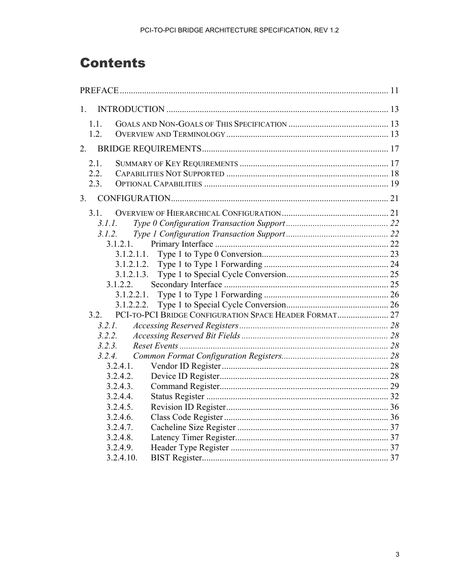
PCI-TO-PCI BRIDGE ARCHITECTURE SPECIFICATION, REV 1.2 Contents PREFACE......................................................................................................................... 11 3.1.1. 3.1.2. 3.1.2.1. 3.2. 1. INTRODUCTION .................................................................................................... 13 1.1. GOALS AND NON-GOALS OF THIS SPECIFICATION ............................................. 13 1.2. OVERVIEW AND TERMINOLOGY......................................................................... 13 2. BRIDGE REQUIREMENTS.................................................................................... 17 2.1. SUMMARY OF KEY REQUIREMENTS ................................................................... 17 2.2. CAPABILITIES NOT SUPPORTED ......................................................................... 18 2.3. OPTIONAL CAPABILITIES ................................................................................... 19 3. CONFIGURATION.................................................................................................. 21 3.1. OVERVIEW OF HIERARCHICAL CONFIGURATION................................................ 21 Type 0 Configuration Transaction Support.............................................. 22 Type 1 Configuration Transaction Support.............................................. 22 Primary Interface .............................................................................. 22 3.1.2.1.1. Type 1 to Type 0 Conversion......................................................... 23 3.1.2.1.2. Type 1 to Type 1 Forwarding ........................................................ 24 3.1.2.1.3. Type 1 to Special Cycle Conversion.............................................. 25 Secondary Interface .......................................................................... 25 3.1.2.2.1. Type 1 to Type 1 Forwarding ........................................................ 26 3.1.2.2.2. Type 1 to Special Cycle Conversion.............................................. 26 PCI-TO-PCI BRIDGE CONFIGURATION SPACE HEADER FORMAT....................... 27 Accessing Reserved Registers................................................................... 28 Accessing Reserved Bit Fields .................................................................. 28 Reset Events .............................................................................................. 28 Common Format Configuration Registers................................................ 28 Vendor ID Register........................................................................... 28 3.2.4.1. Device ID Register............................................................................ 28 3.2.4.2. Command Register............................................................................ 29 3.2.4.3. Status Register .................................................................................. 32 3.2.4.4. Revision ID Register......................................................................... 36 3.2.4.5. Class Code Register .......................................................................... 36 3.2.4.6. Cacheline Size Register .................................................................... 37 3.2.4.7. Latency Timer Register..................................................................... 37 3.2.4.8. 3.2.4.9. Header Type Register ....................................................................... 37 3.2.4.10. BIST Register.................................................................................... 37 3.2.1. 3.2.2. 3.2.3. 3.2.4. 3.1.2.2. 3
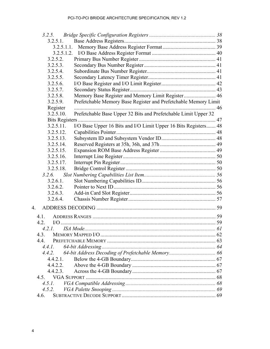
PCI-TO-PCI BRIDGE ARCHITECTURE SPECIFICATION, REV 1.2 3.2.5. 3.2.5.1. Bridge Specific Configuration Registers .................................................. 38 Base Address Registers..................................................................... 38 3.2.5.1.1. Memory Base Address Register Format........................................ 39 I/O Base Address Register Format ................................................ 40 3.2.5.1.2. Primary Bus Number Register.......................................................... 41 3.2.5.2. Secondary Bus Number Register...................................................... 41 3.2.5.3. Subordinate Bus Number Register.................................................... 41 3.2.5.4. Secondary Latency Timer Register................................................... 41 3.2.5.5. I/O Base Register and I/O Limit Register......................................... 42 3.2.5.6. 3.2.5.7. Secondary Status Register................................................................. 43 3.2.5.8. Memory Base Register and Memory Limit Register........................ 46 3.2.5.9. Prefetchable Memory Base Register and Prefetchable Memory Limit ........................................................................................................... 46 Register 3.2.5.10. Prefetchable Base Upper 32 Bits and Prefetchable Limit Upper 32 Bits Registers ........................................................................................................ 47 3.2.5.11. I/O Base Upper 16 Bits and I/O Limit Upper 16 Bits Registers....... 48 3.2.5.12. Capabilities Pointer........................................................................... 48 3.2.5.13. Subsystem ID and Subsystem Vendor ID......................................... 48 3.2.5.14. Reserved Registers at 35h, 36h, and 37h .......................................... 49 Expansion ROM Base Address Register .......................................... 49 3.2.5.15. Interrupt Line Register...................................................................... 50 3.2.5.16. 3.2.5.17. Interrupt Pin Register........................................................................ 50 3.2.5.18. Bridge Control Register .................................................................... 50 Slot Numbering Capabilities List Item...................................................... 56 Slot Numbering Capabilities ID........................................................ 56 Pointer to Next ID............................................................................. 56 Add-in Card Slot Register................................................................. 56 Chassis Number Register.................................................................. 57 4. ADDRESS DECODING .......................................................................................... 59 4.1. ADDRESS RANGES ............................................................................................. 59 I/O ..................................................................................................................... 59 4.2. ISA Mode................................................................................................... 61 4.3. MEMORY MAPPED I/O....................................................................................... 62 PREFETCHABLE MEMORY .................................................................................. 63 4.4. 64-bit Addressing...................................................................................... 64 64-bit Address Decoding of Prefetchable Memory................................... 66 Below the 4-GB Boundary................................................................ 67 Above the 4-GB Boundary ............................................................... 67 Across the 4-GB Boundary............................................................... 67 4.5. VGA SUPPORT .................................................................................................. 68 VGA Compatible Addressing .................................................................... 68 VGA Palette Snooping .............................................................................. 69 SUBTRACTIVE DECODE SUPPORT....................................................................... 69 3.2.6.1. 3.2.6.2. 3.2.6.3. 3.2.6.4. 4.4.2.1. 4.4.2.2. 4.4.2.3. 4.5.1. 4.5.2. 4.6. 3.2.6. 4.2.1. 4.4.1. 4.4.2. 4
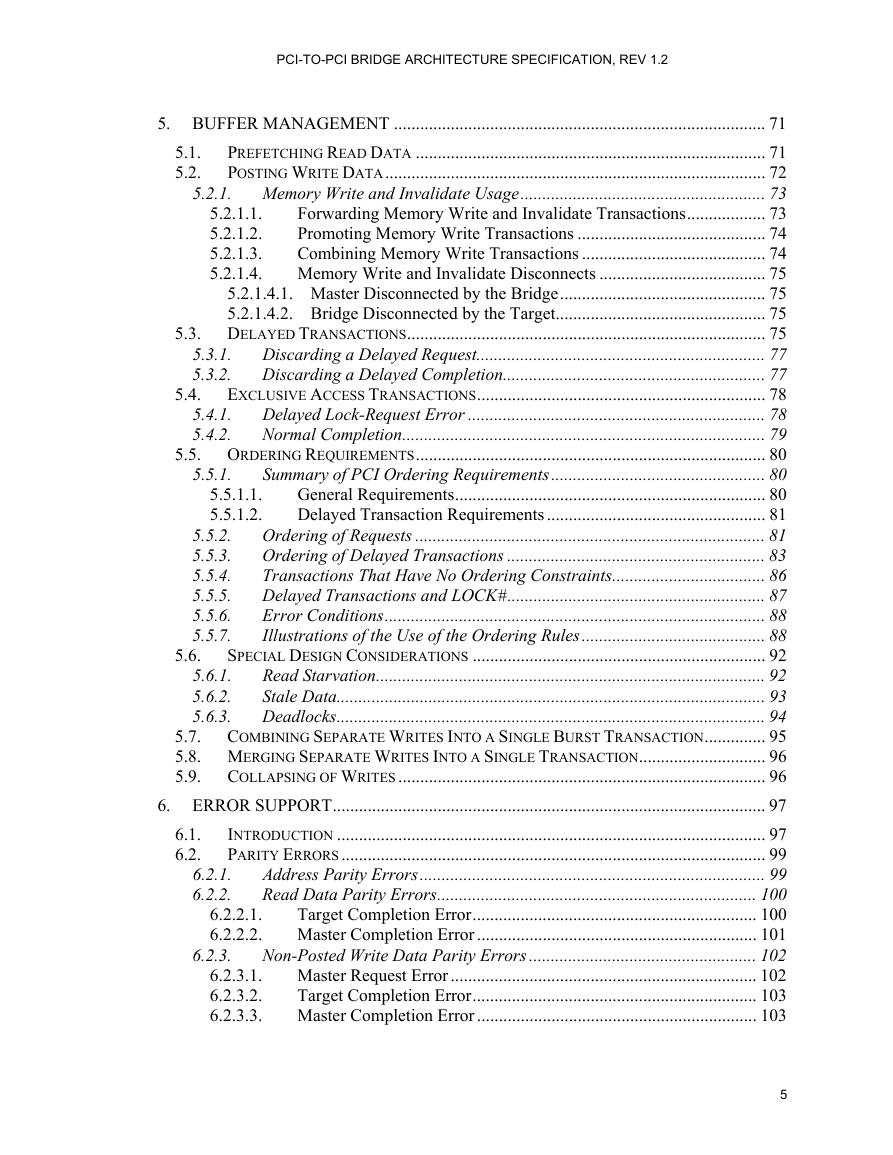
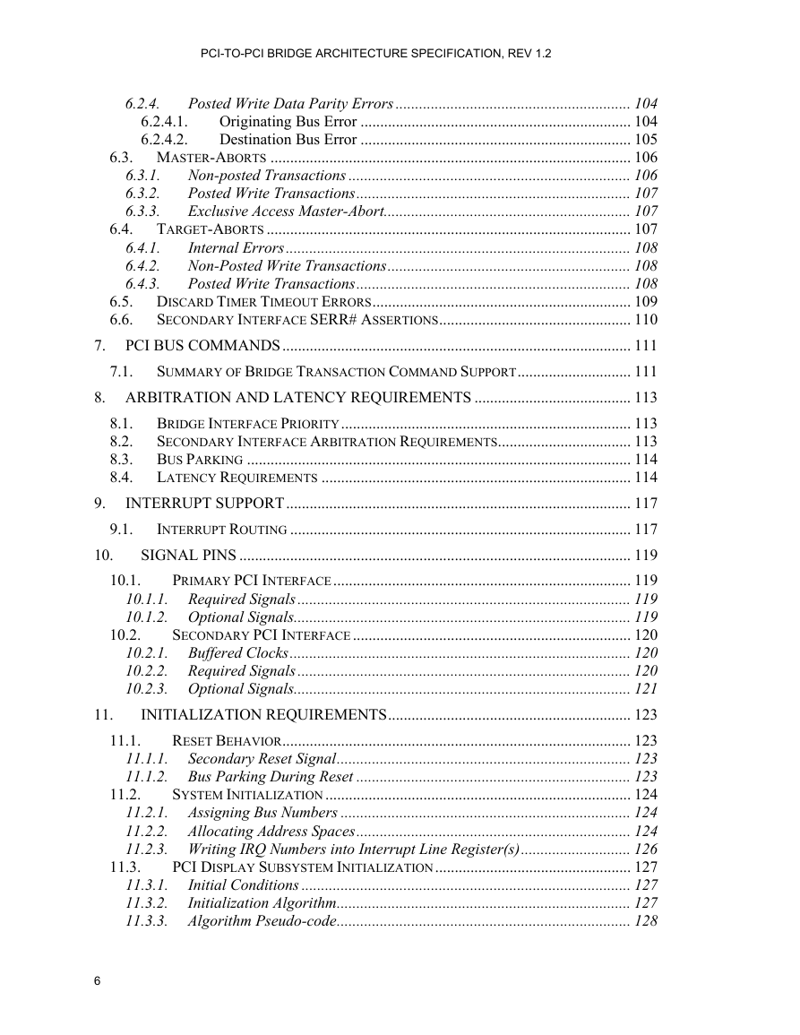
PCI-TO-PCI BRIDGE ARCHITECTURE SPECIFICATION, REV 1.2 5.4. 5.6. 5.1. 5.2. 5.3.1. 5.3.2. 5.4.1. 5.4.2. 5.5.1. 5.5.1.1. 5.5.1.2. 5. BUFFER MANAGEMENT ..................................................................................... 71 PREFETCHING READ DATA ................................................................................ 71 POSTING WRITE DATA....................................................................................... 72 5.2.1. Memory Write and Invalidate Usage........................................................ 73 Forwarding Memory Write and Invalidate Transactions.................. 73 5.2.1.1. Promoting Memory Write Transactions ........................................... 74 5.2.1.2. Combining Memory Write Transactions .......................................... 74 5.2.1.3. 5.2.1.4. Memory Write and Invalidate Disconnects ...................................... 75 5.2.1.4.1. Master Disconnected by the Bridge............................................... 75 5.2.1.4.2. Bridge Disconnected by the Target................................................ 75 5.3. DELAYED TRANSACTIONS.................................................................................. 75 Discarding a Delayed Request.................................................................. 77 Discarding a Delayed Completion............................................................ 77 EXCLUSIVE ACCESS TRANSACTIONS.................................................................. 78 Delayed Lock-Request Error .................................................................... 78 Normal Completion................................................................................... 79 5.5. ORDERING REQUIREMENTS................................................................................ 80 Summary of PCI Ordering Requirements................................................. 80 General Requirements....................................................................... 80 Delayed Transaction Requirements .................................................. 81 Ordering of Requests ................................................................................ 81 Ordering of Delayed Transactions ........................................................... 83 Transactions That Have No Ordering Constraints................................... 86 Delayed Transactions and LOCK#........................................................... 87 Error Conditions....................................................................................... 88 Illustrations of the Use of the Ordering Rules.......................................... 88 SPECIAL DESIGN CONSIDERATIONS ................................................................... 92 Read Starvation......................................................................................... 92 Stale Data.................................................................................................. 93 Deadlocks.................................................................................................. 94 5.7. COMBINING SEPARATE WRITES INTO A SINGLE BURST TRANSACTION.............. 95 5.8. MERGING SEPARATE WRITES INTO A SINGLE TRANSACTION............................. 96 5.9. COLLAPSING OF WRITES .................................................................................... 96 6. ERROR SUPPORT................................................................................................... 97 INTRODUCTION .................................................................................................. 97 PARITY ERRORS................................................................................................. 99 Address Parity Errors............................................................................... 99 Read Data Parity Errors......................................................................... 100 Target Completion Error................................................................. 100 6.2.2.1. 6.2.2.2. Master Completion Error ................................................................ 101 Non-Posted Write Data Parity Errors .................................................... 102 6.2.3.1. Master Request Error ...................................................................... 102 6.2.3.2. Target Completion Error................................................................. 103 6.2.3.3. Master Completion Error ................................................................ 103 5.5.2. 5.5.3. 5.5.4. 5.5.5. 5.5.6. 5.5.7. 5.6.1. 5.6.2. 5.6.3. 6.1. 6.2. 6.2.1. 6.2.2. 6.2.3. 5
PCI-TO-PCI BRIDGE ARCHITECTURE SPECIFICATION, REV 1.2 6.2.4. 6.4. 7.1. 6.2.4.1. 6.2.4.2. 6.4.1. 6.4.2. 6.4.3. 6.3.1. 6.3.2. 6.3.3. Posted Write Data Parity Errors ............................................................ 104 Originating Bus Error ..................................................................... 104 Destination Bus Error ..................................................................... 105 6.3. MASTER-ABORTS ............................................................................................ 106 Non-posted Transactions ........................................................................ 106 Posted Write Transactions...................................................................... 107 Exclusive Access Master-Abort............................................................... 107 TARGET-ABORTS ............................................................................................. 107 Internal Errors........................................................................................ 108 Non-Posted Write Transactions.............................................................. 108 Posted Write Transactions...................................................................... 108 6.5. DISCARD TIMER TIMEOUT ERRORS.................................................................. 109 SECONDARY INTERFACE SERR# ASSERTIONS................................................. 110 6.6. 7. PCI BUS COMMANDS......................................................................................... 111 SUMMARY OF BRIDGE TRANSACTION COMMAND SUPPORT............................. 111 8. ARBITRATION AND LATENCY REQUIREMENTS ........................................ 113 8.1. BRIDGE INTERFACE PRIORITY.......................................................................... 113 8.2. SECONDARY INTERFACE ARBITRATION REQUIREMENTS.................................. 113 8.3. BUS PARKING .................................................................................................. 114 8.4. LATENCY REQUIREMENTS ............................................................................... 114 INTERRUPT SUPPORT........................................................................................ 117 INTERRUPT ROUTING ....................................................................................... 117 SIGNAL PINS .................................................................................................... 119 PRIMARY PCI INTERFACE............................................................................ 119 10.1.1. Required Signals ..................................................................................... 119 10.1.2. Optional Signals...................................................................................... 119 SECONDARY PCI INTERFACE....................................................................... 120 10.2.1. Buffered Clocks....................................................................................... 120 10.2.2. Required Signals ..................................................................................... 120 10.2.3. Optional Signals...................................................................................... 121 INITIALIZATION REQUIREMENTS.............................................................. 123 RESET BEHAVIOR......................................................................................... 123 11.1.1. Secondary Reset Signal........................................................................... 123 11.1.2. Bus Parking During Reset ...................................................................... 123 SYSTEM INITIALIZATION.............................................................................. 124 11.2.1. Assigning Bus Numbers .......................................................................... 124 11.2.2. Allocating Address Spaces...................................................................... 124 11.2.3. Writing IRQ Numbers into Interrupt Line Register(s)............................ 126 PCI DISPLAY SUBSYSTEM INITIALIZATION.................................................. 127 Initial Conditions .................................................................................... 127 11.3.1. 11.3.2. Initialization Algorithm........................................................................... 127 11.3.3. Algorithm Pseudo-code........................................................................... 128 9. 10. 9.1. 11. 11.1. 10.1. 10.2. 11.2. 11.3. 6
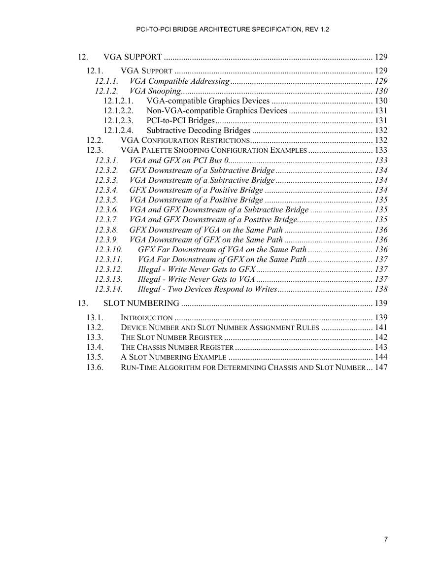
PCI-TO-PCI BRIDGE ARCHITECTURE SPECIFICATION, REV 1.2 12. 12.1. 12.2. 12.3. 13. 13.1. 13.2. 13.3. 13.4. 13.5. 13.6. VGA SUPPORT ................................................................................................. 129 VGA SUPPORT ............................................................................................ 129 12.1.1. VGA Compatible Addressing .................................................................. 129 12.1.2. VGA Snooping......................................................................................... 130 12.1.2.1. VGA-compatible Graphics Devices ............................................... 130 12.1.2.2. Non-VGA-compatible Graphics Devices ....................................... 131 PCI-to-PCI Bridges......................................................................... 131 12.1.2.3. 12.1.2.4. Subtractive Decoding Bridges ........................................................ 132 VGA CONFIGURATION RESTRICTIONS......................................................... 132 VGA PALETTE SNOOPING CONFIGURATION EXAMPLES.............................. 133 12.3.1. VGA and GFX on PCI Bus 0................................................................... 133 12.3.2. GFX Downstream of a Subtractive Bridge ............................................. 134 12.3.3. VGA Downstream of a Subtractive Bridge ............................................. 134 12.3.4. GFX Downstream of a Positive Bridge .................................................. 134 12.3.5. VGA Downstream of a Positive Bridge .................................................. 135 12.3.6. VGA and GFX Downstream of a Subtractive Bridge ............................. 135 12.3.7. VGA and GFX Downstream of a Positive Bridge................................... 135 12.3.8. GFX Downstream of VGA on the Same Path ......................................... 136 12.3.9. VGA Downstream of GFX on the Same Path ......................................... 136 GFX Far Downstream of VGA on the Same Path .............................. 136 12.3.10. VGA Far Downstream of GFX on the Same Path .............................. 137 12.3.11. 12.3.12. Illegal - Write Never Gets to GFX ...................................................... 137 Illegal - Write Never Gets to VGA ...................................................... 137 12.3.13. 12.3.14. Illegal - Two Devices Respond to Writes............................................ 138 SLOT NUMBERING ......................................................................................... 139 INTRODUCTION ............................................................................................ 139 DEVICE NUMBER AND SLOT NUMBER ASSIGNMENT RULES ........................ 141 THE SLOT NUMBER REGISTER ..................................................................... 142 THE CHASSIS NUMBER REGISTER ................................................................ 143 A SLOT NUMBERING EXAMPLE ................................................................... 144 RUN-TIME ALGORITHM FOR DETERMINING CHASSIS AND SLOT NUMBER... 147 7
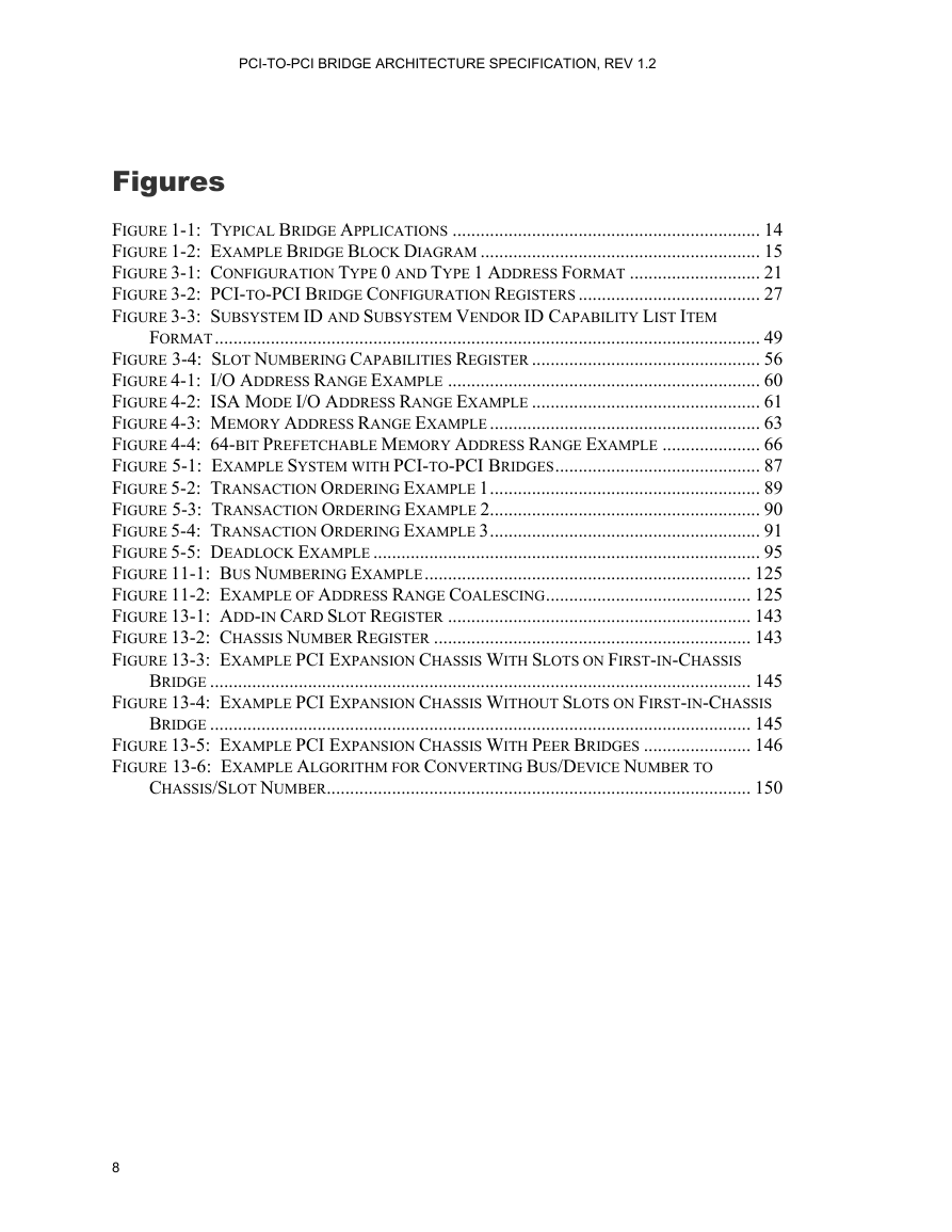
PCI-TO-PCI BRIDGE ARCHITECTURE SPECIFICATION, REV 1.2 Figures FIGURE 1-1: TYPICAL BRIDGE APPLICATIONS .................................................................. 14 FIGURE 1-2: EXAMPLE BRIDGE BLOCK DIAGRAM ............................................................ 15 FIGURE 3-1: CONFIGURATION TYPE 0 AND TYPE 1 ADDRESS FORMAT ............................ 21 FIGURE 3-2: PCI-TO-PCI BRIDGE CONFIGURATION REGISTERS ....................................... 27 FIGURE 3-3: SUBSYSTEM ID AND SUBSYSTEM VENDOR ID CAPABILITY LIST ITEM FORMAT..................................................................................................................... 49 FIGURE 3-4: SLOT NUMBERING CAPABILITIES REGISTER ................................................. 56 FIGURE 4-1: I/O ADDRESS RANGE EXAMPLE ................................................................... 60 FIGURE 4-2: ISA MODE I/O ADDRESS RANGE EXAMPLE ................................................. 61 FIGURE 4-3: MEMORY ADDRESS RANGE EXAMPLE .......................................................... 63 FIGURE 4-4: 64-BIT PREFETCHABLE MEMORY ADDRESS RANGE EXAMPLE ..................... 66 FIGURE 5-1: EXAMPLE SYSTEM WITH PCI-TO-PCI BRIDGES............................................ 87 FIGURE 5-2: TRANSACTION ORDERING EXAMPLE 1.......................................................... 89 FIGURE 5-3: TRANSACTION ORDERING EXAMPLE 2.......................................................... 90 FIGURE 5-4: TRANSACTION ORDERING EXAMPLE 3.......................................................... 91 FIGURE 5-5: DEADLOCK EXAMPLE ................................................................................... 95 FIGURE 11-1: BUS NUMBERING EXAMPLE...................................................................... 125 FIGURE 11-2: EXAMPLE OF ADDRESS RANGE COALESCING............................................ 125 FIGURE 13-1: ADD-IN CARD SLOT REGISTER ................................................................. 143 FIGURE 13-2: CHASSIS NUMBER REGISTER .................................................................... 143 FIGURE 13-3: EXAMPLE PCI EXPANSION CHASSIS WITH SLOTS ON FIRST-IN-CHASSIS BRIDGE .................................................................................................................... 145 FIGURE 13-4: EXAMPLE PCI EXPANSION CHASSIS WITHOUT SLOTS ON FIRST-IN-CHASSIS BRIDGE .................................................................................................................... 145 FIGURE 13-5: EXAMPLE PCI EXPANSION CHASSIS WITH PEER BRIDGES ....................... 146 FIGURE 13-6: EXAMPLE ALGORITHM FOR CONVERTING BUS/DEVICE NUMBER TO CHASSIS/SLOT NUMBER........................................................................................... 150 8
分享到:
收藏