logo资料库

AMC.1手册,网上根本找不到的。.pdf

第1页 / 共64页
第2页 / 共64页
第3页 / 共64页
第4页 / 共64页
第5页 / 共64页
第6页 / 共64页
第7页 / 共64页
第8页 / 共64页
资料共64页,剩余部分请下载后查看
Introduction 1
1.1 Scope
1.2 Reference Documents
1.2.1 Reference specifications
1.2.2 Environment and Regulatory Documents
1.3 Contributors
1.4 AMC.1 officers
1.5 Special Word Usage
1.6 Name and Logo Usage
1.6.1 Logo Usage
1.6.2 Trademark Policy
1.7 Signal Naming Conventions
1.8 Intellectual Property
1.9 Acronyms and Definitions
PICMG® AMC.1 Compliance 2
AMC.0 3
3.1 AMC.0 Compliance
3.2 AMC.0 Port Mapping
3.3 Port Definition
Common Fabric I/O Specification 4
4.1 Common Electrical and Link Layer Rules
4.2 Dual-Mode Support
4.3 Ports and Link Widths
4.4 AMC.0 Basic and Extended Connector Support
PCI Express 5
5.1 Introduction
5.2 PCI Express Compliance
5.3 PCI Express Parameters
5.3.1 Primary and Secondary PCI Express ports
5.3.2 Multiple Hosts
5.4 Type P Control Path Support
Advanced Switching 6
6.1 Introduction
6.2 Advanced Switching Compliance
Signal Integrity 7
7.1 PCI Express @ 2.5 Gbps
7.1.1 Minimum Receiver Requirements at 2.5 Gbps
7.1.2 AMC Signal Integrity Requirements and Results for 2.5 Gbps
7.2 PCI Express at 5 Gbps
7.2.1 Minimum Receiver Requirements at 5 Gbps
7.2.2 AMC Signal Integrity Requirements and Results at 5 Gbps
Management and E-Keying 8
8.1 AMC E-Keying Introduction
8.1.1 Carrier Point-to-Point Connectivity Record
8.2 Record Type
8.3 AMC Channel Descriptor Count
8.4 AMC Channel Descriptors
8.5 AMC Link Descriptors
8.5.1 AMC Link Designator
8.5.2 AMC Link Type
8.5.3 Asymmetric Match
8.5.4 Link Grouping ID
AMC.0 Pin Assignments A
Carrier Topologies (Informative) B
B.1 Basic PCI-E I/O Carrier, or With RC on the Carrier
B.2 Basic AS Carrier
B.3 PCI-E Carrier Which Supports an RC on a Module
B.4 PCI-E Carrier Which Supports Primary and Secondary RC With NTB and Failover Support
B.5 Mixed-mode AS and PCI-E Carrier
B.6 Basic PCI-E Carrier with private busses
B.7 Carrier populated with NTB-isolated RC Modules creating a compute farm
B.8 Carrier using Type P PCI-E x1 Control Bus and Some Other Fabric e.g., AMC.3 FC
Signal Integrity Analysis C
C.1 Signal Integrity Analysis Overview
C.1.1 Modeling Parameters
C.1.2 Module Stackup and Via Details
C.1.3 Carrier Stackup and Via Details
C.2 Simulation Models
C.2.1 Module to Carrier and Carrier to Module Serial Link
C.2.2 Module to Carrier to Module Serial Link
C.2.3 Representative Eye Patterns
AMC.1 - PCI Express and Advanced Switching A subsidiary specification to AMC.0 (Draft 0.9a of AMC.1 Revision 1.0) Sponsor: PICMG AMC.1 Subcommittee of the PICMG special interest group Approved xx/xx/2004 (anticipated) PICMG BoD Do Not Specify or Claim Compliance to this Draft Specification Abstract: AMC.1 specifies Port allocation and usage for implementing PCI Express and Advanced Switching on an AMC.0 compliant Module and On-Carrier device. The intent is that this specification will cre- ate a unified industry approach so as to encourage interoperable and “plug-and-play” implementa- tions. AMC.1 is a subsidiary specification and is therefore dependent upon AMC.0 for definition of all mechanical, management, thermal, power and interconnect requirements.
ii PICMG AMC.1 PCI Express and Advanced Switching Specification D0.9a, September 20, 2004 Do not specify or claim compliance with this Draft Specification
 Copyright 2004, PCI Industrial Computer Manufacturers Group. The attention of adopters is directed to the possibility that compliance with or adoption of PICMG® specifications may require use of an invention covered by patent rights. PICMG® shall not be responsible for identifying patents for which a license may be required by any PICMG® specification or for conducting legal inquiries into the legal validity or scope of those patents that are brought to its attention. PICMG® specifications are prospective and advisory only. Prospective users are responsible for protecting themselves against liability for infringement of patents. NOTICE: The information contained in this document is subject to change without notice. The material in this document details a PICMG® specification in accordance with the license and notices set forth on this page. This document does not represent a commitment to implement any portion of this specification in any company's products. WHILE THE INFORMATION IN THIS PUBLICATION IS BELIEVED TO BE ACCURATE, PICMG® MAKES NO WARRANTY OF ANY KIND, EXPRESS OR IMPLIED, WITH REGARD TO THIS MATERIAL INCLUDING, BUT NOT LIMITED TO ANY WARRANTY OF TITLE OR OWNERSHIP, IMPLIED WARRANTY OF MERCHANTABILITY OR WARRANTY OF FITNESS FOR PARTICULAR PURPOSE OR USE. In no event shall PICMG® be liable for errors contained herein or for indirect, incidental, special, consequential, reliance or cover damages, including loss of profits, revenue, data or use, incurred by any user or any third party. Compliance with this specification does not absolve manufacturers of AdvancedTCA® equipment from the requirements of safety and regulatory agencies (UL, CSA, FCC, IEC, etc.). The PICMG® and AdvancedTCA® logos are registered trademarks and ATCA is a trademark of the PCI Industrial Computer Manufacturers Group. All other brand or product names may be trademarks or registered trademarks of their respective holders. PICMG AMC.1 PCI Express and Advanced Switching Specification D0.9a, September 20, 2004 Do not specify or claim compliance with this Draft Specification iii
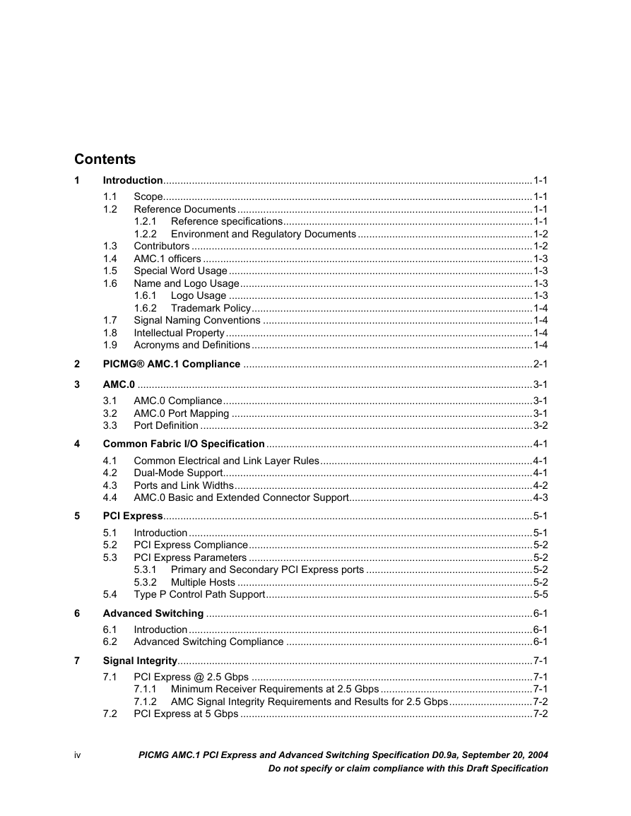
Contents 1 2 3 4 5 6 7 iv 1.3 1.4 1.5 1.6 Introduction.................................................................................................................................1-1 Scope.................................................................................................................................1-1 1.1 Reference Documents.......................................................................................................1-1 1.2 1.2.1 Reference specifications.......................................................................................1-1 1.2.2 Environment and Regulatory Documents .............................................................1-2 Contributors .......................................................................................................................1-2 AMC.1 officers ...................................................................................................................1-3 Special Word Usage..........................................................................................................1-3 Name and Logo Usage......................................................................................................1-3 Logo Usage ..........................................................................................................1-3 1.6.1 1.6.2 Trademark Policy..................................................................................................1-4 1.7 Signal Naming Conventions ..............................................................................................1-4 1.8 Intellectual Property...........................................................................................................1-4 1.9 Acronyms and Definitions..................................................................................................1-4 PICMG® AMC.1 Compliance .....................................................................................................2-1 AMC.0 ..........................................................................................................................................3-1 AMC.0 Compliance............................................................................................................3-1 3.1 AMC.0 Port Mapping .........................................................................................................3-1 3.2 3.3 Port Definition ....................................................................................................................3-2 Common Fabric I/O Specification.............................................................................................4-1 Common Electrical and Link Layer Rules..........................................................................4-1 4.1 Dual-Mode Support............................................................................................................4-1 4.2 4.3 Ports and Link Widths........................................................................................................4-2 4.4 AMC.0 Basic and Extended Connector Support................................................................4-3 PCI Express.................................................................................................................................5-1 Introduction........................................................................................................................5-1 5.1 5.2 PCI Express Compliance...................................................................................................5-2 PCI Express Parameters ...................................................................................................5-2 5.3 5.3.1 Primary and Secondary PCI Express ports ..........................................................5-2 5.3.2 Multiple Hosts .......................................................................................................5-2 Type P Control Path Support.............................................................................................5-5 5.4 Advanced Switching ..................................................................................................................6-1 Introduction........................................................................................................................6-1 6.1 6.2 Advanced Switching Compliance ......................................................................................6-1 Signal Integrity............................................................................................................................7-1 PCI Express @ 2.5 Gbps ..................................................................................................7-1 7.1 7.1.1 Minimum Receiver Requirements at 2.5 Gbps .....................................................7-1 7.1.2 AMC Signal Integrity Requirements and Results for 2.5 Gbps.............................7-2 PCI Express at 5 Gbps ......................................................................................................7-2 7.2 PICMG AMC.1 PCI Express and Advanced Switching Specification D0.9a, September 20, 2004 Do not specify or claim compliance with this Draft Specification
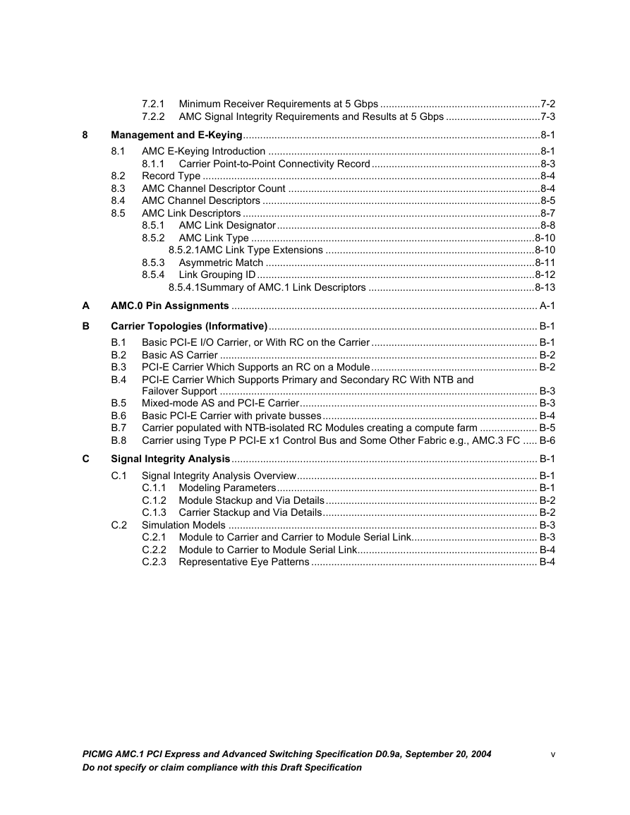
8 A B C 8.2 8.3 8.4 8.5 7.2.1 Minimum Receiver Requirements at 5 Gbps ........................................................7-2 7.2.2 AMC Signal Integrity Requirements and Results at 5 Gbps .................................7-3 Management and E-Keying........................................................................................................8-1 AMC E-Keying Introduction ...............................................................................................8-1 8.1 8.1.1 Carrier Point-to-Point Connectivity Record...........................................................8-3 Record Type ......................................................................................................................8-4 AMC Channel Descriptor Count ........................................................................................8-4 AMC Channel Descriptors .................................................................................................8-5 AMC Link Descriptors ........................................................................................................8-7 AMC Link Designator............................................................................................8-8 8.5.1 8.5.2 AMC Link Type ...................................................................................................8-10 8.5.2.1AMC Link Type Extensions .........................................................................8-10 Asymmetric Match ..............................................................................................8-11 Link Grouping ID.................................................................................................8-12 8.5.4.1Summary of AMC.1 Link Descriptors ..........................................................8-13 AMC.0 Pin Assignments ........................................................................................................... A-1 Carrier Topologies (Informative).............................................................................................. B-1 B.1 Basic PCI-E I/O Carrier, or With RC on the Carrier .......................................................... B-1 Basic AS Carrier ............................................................................................................... B-2 B.2 PCI-E Carrier Which Supports an RC on a Module.......................................................... B-2 B.3 PCI-E Carrier Which Supports Primary and Secondary RC With NTB and B.4 Failover Support ............................................................................................................... B-3 B.5 Mixed-mode AS and PCI-E Carrier................................................................................... B-3 Basic PCI-E Carrier with private busses........................................................................... B-4 B.6 Carrier populated with NTB-isolated RC Modules creating a compute farm .................... B-5 B.7 B.8 Carrier using Type P PCI-E x1 Control Bus and Some Other Fabric e.g., AMC.3 FC ..... B-6 Signal Integrity Analysis........................................................................................................... B-1 Signal Integrity Analysis Overview.................................................................................... B-1 C.1 C.1.1 Modeling Parameters........................................................................................... B-1 C.1.2 Module Stackup and Via Details.......................................................................... B-2 C.1.3 Carrier Stackup and Via Details........................................................................... B-2 Simulation Models ............................................................................................................ B-3 C.2.1 Module to Carrier and Carrier to Module Serial Link............................................ B-3 C.2.2 Module to Carrier to Module Serial Link............................................................... B-4 C.2.3 Representative Eye Patterns ............................................................................... B-4 8.5.3 8.5.4 C.2 PICMG AMC.1 PCI Express and Advanced Switching Specification D0.9a, September 20, 2004 Do not specify or claim compliance with this Draft Specification v
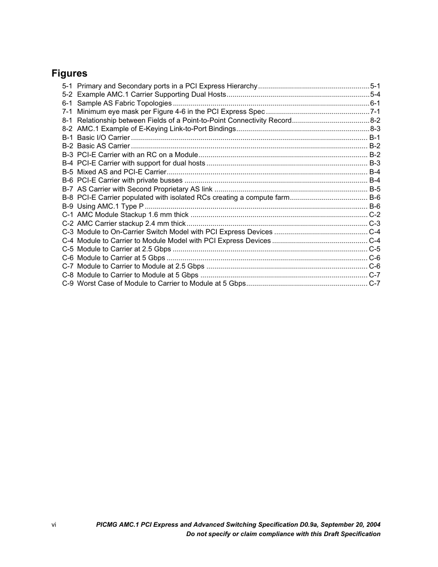
Figures 5-1 Primary and Secondary ports in a PCI Express Hierarchy........................................................5-1 5-2 Example AMC.1 Carrier Supporting Dual Hosts........................................................................5-4 6-1 Sample AS Fabric Topologies ...................................................................................................6-1 7-1 Minimum eye mask per Figure 4-6 in the PCI Express Spec ....................................................7-1 8-1 Relationship between Fields of a Point-to-Point Connectivity Record.......................................8-2 8-2 AMC.1 Example of E-Keying Link-to-Port Bindings...................................................................8-3 B-1 Basic I/O Carrier ....................................................................................................................... B-1 B-2 Basic AS Carrier ....................................................................................................................... B-2 B-3 PCI-E Carrier with an RC on a Module..................................................................................... B-2 B-4 PCI-E Carrier with support for dual hosts ................................................................................. B-3 B-5 Mixed AS and PCI-E Carrier..................................................................................................... B-4 B-6 PCI-E Carrier with private busses ............................................................................................ B-4 B-7 AS Carrier with Second Proprietary AS link ............................................................................. B-5 B-8 PCI-E Carrier populated with isolated RCs creating a compute farm....................................... B-6 B-9 Using AMC.1 Type P ................................................................................................................ B-6 C-1 AMC Module Stackup 1.6 mm thick ......................................................................................... C-2 C-2 AMC Carrier stackup 2.4 mm thick........................................................................................... C-3 C-3 Module to On-Carrier Switch Model with PCI Express Devices ............................................... C-4 C-4 Module to Carrier to Module Model with PCI Express Devices ................................................ C-4 C-5 Module to Carrier at 2.5 Gbps .................................................................................................. C-5 C-6 Module to Carrier at 5 Gbps ..................................................................................................... C-6 C-7 Module to Carrier to Module at 2.5 Gbps ................................................................................. C-6 C-8 Module to Carrier to Module at 5 Gbps .................................................................................... C-7 C-9 Worst Case of Module to Carrier to Module at 5 Gbps............................................................. C-7 vi PICMG AMC.1 PCI Express and Advanced Switching Specification D0.9a, September 20, 2004 Do not specify or claim compliance with this Draft Specification
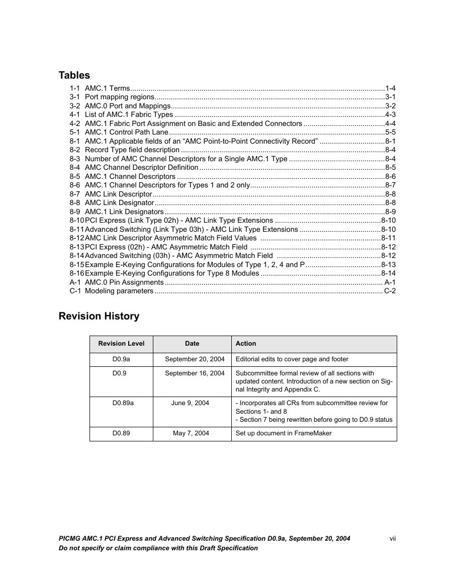
Tables 1-1 AMC.1 Terms.............................................................................................................................1-4 3-1 Port mapping regions.................................................................................................................3-1 3-2 AMC.0 Port and Mappings.........................................................................................................3-2 4-1 List of AMC.1 Fabric Types .......................................................................................................4-3 4-2 AMC.1 Fabric Port Assignment on Basic and Extended Connectors ........................................4-4 5-1 AMC.1 Control Path Lane..........................................................................................................5-5 8-1 AMC.1 Applicable fields of an “AMC Point-to-Point Connectivity Record” ................................8-1 8-2 Record Type field description ....................................................................................................8-4 8-3 Number of AMC Channel Descriptors for a Single AMC.1 Type ...............................................8-4 8-4 AMC Channel Descriptor Definition ...........................................................................................8-5 8-5 AMC.1 Channel Descriptors ......................................................................................................8-6 8-6 AMC.1 Channel Descriptors for Types 1 and 2 only..................................................................8-7 8-7 AMC Link Descriptor..................................................................................................................8-8 8-8 AMC Link Designator.................................................................................................................8-8 8-9 AMC.1 Link Designators............................................................................................................8-9 8-10PCI Express (Link Type 02h) - AMC Link Type Extensions ....................................................8-10 8-11Advanced Switching (Link Type 03h) - AMC Link Type Extensions ........................................8-10 8-12AMC Link Descriptor Asymmetric Match Field Values ...........................................................8-11 8-13PCI Express (02h) - AMC Asymmetric Match Field ................................................................8-12 8-14Advanced Switching (03h) - AMC Asymmetric Match Field ...................................................8-12 8-15Example E-Keying Configurations for Modules of Type 1, 2, 4 and P.....................................8-13 8-16Example E-Keying Configurations for Type 8 Modules ...........................................................8-14 A-1 AMC.0 Pin Assignments........................................................................................................... A-1 C-1 Modeling parameters................................................................................................................ C-2 Revision History Revision Level Date Action September 20, 2004 Editorial edits to cover page and footer D0.9a D0.9 September 16, 2004 D0.89a June 9, 2004 Subcommittee formal review of all sections with updated content. Introduction of a new section on Sig- nal Integrity and Appendix C. - Incorporates all CRs from subcommittee review for Sections 1- and 8 - Section 7 being rewritten before going to D0.9 status D0.89 May 7, 2004 Set up document in FrameMaker PICMG AMC.1 PCI Express and Advanced Switching Specification D0.9a, September 20, 2004 Do not specify or claim compliance with this Draft Specification vii
viii PICMG AMC.1 PCI Express and Advanced Switching Specification D0.9a, September 20, 2004 Do not specify or claim compliance with this Draft Specification
分享到:
收藏