Zynq-7000 SoC PCB Design Guide
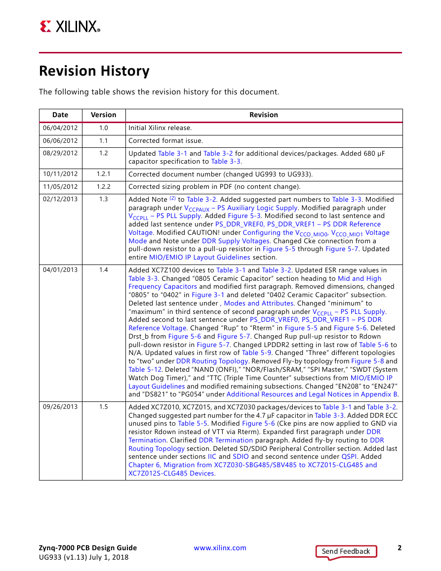
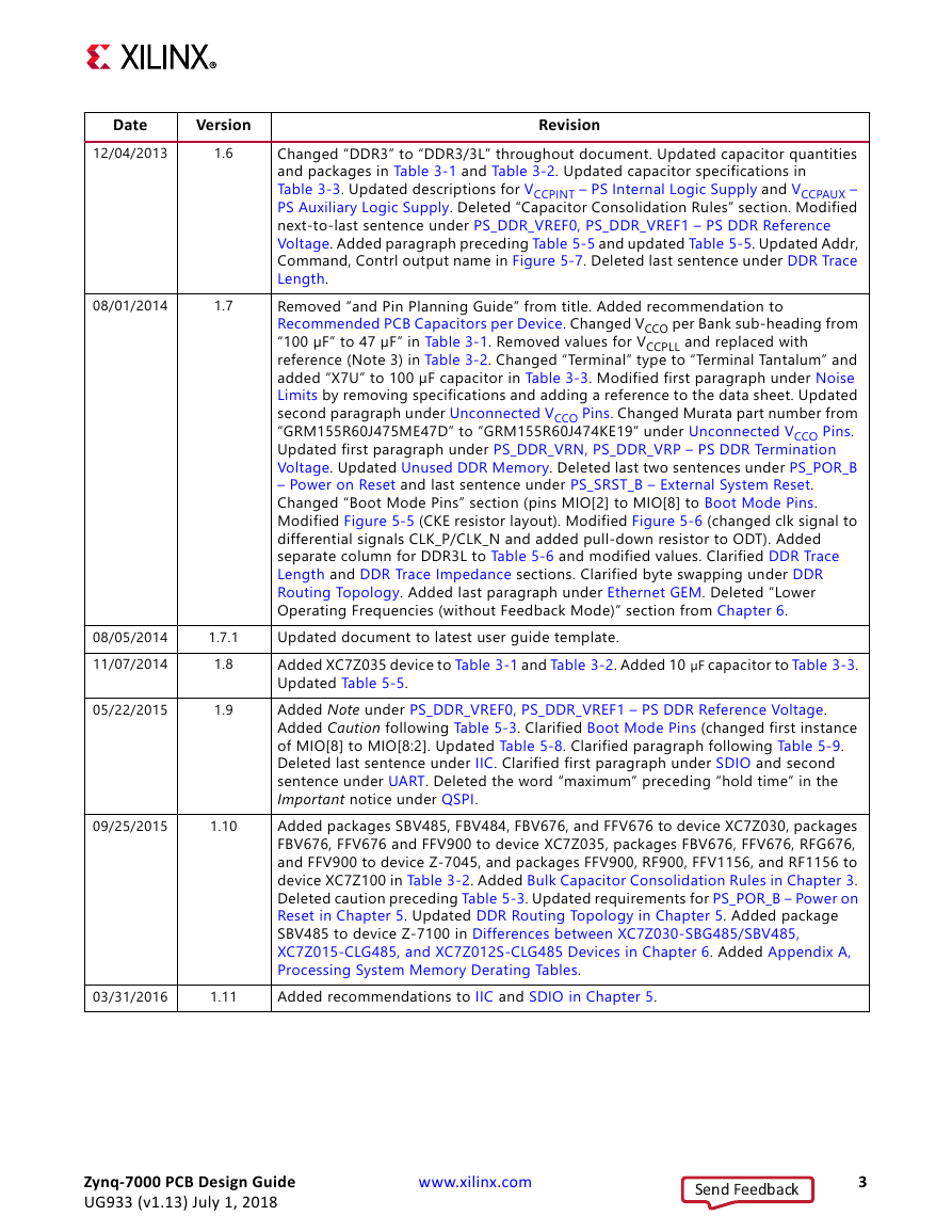
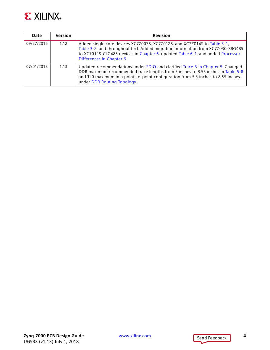
Revision History
Table of Contents
Ch. 1: Introduction
About This Guide
Additional Support Resources
Ch. 2: PCB Technology Basics
Introduction
PCB Structures
Traces
Planes
Vias
Pads and Antipads
Lands
Dimensions
Transmission Lines
Return Currents
Ch. 3: Power Distribution System
Introduction
PCB Decoupling Capacitors
Recommended PCB Capacitors per Device
Required PCB Capacitor Quantities
Capacitor Specifications
PCB Bulk Capacitors
PCB High-Frequency Capacitors
Bulk Capacitor Consolidation Rules
PCB Capacitor Placement and Mounting Techniques
PCB Bulk Capacitors
Mid and High Frequency Capacitors
Basic PDS Principles
Noise Limits
Role of Inductance
Capacitor Parasitic Inductance
PCB Current Path Inductance
Capacitor Mounting Inductance
Plane Inductance
SoC Mounting Inductance
PCB Stackup and Layer Order
Capacitor Effective Frequency
Capacitor Anti-Resonance
Capacitor Placement Background
VREF Stabilization Capacitors
Power Supply Consolidation
Unconnected VCCO Pins
Simulation Methods
PDS Measurements
Noise Magnitude Measurement
Oscilloscope Measurement Methods
3.0.1 Noise Spectrum Measurements
Optimum Decoupling Network Design
Troubleshooting
Possibility 1: Excessive Noise from Other Devices on the PCB
Possibility 2: Parasitic Inductance of Planes, Vias, or Connecting Traces
Possibility 3: I/O Signals in PCB are Stronger Than Necessary
Possibility 4: I/O Signal Return Current Traveling in Sub-Optimal Paths
Ch. 4: SelectIO Signaling
Introduction
Interface Types
Single-Ended versus Differential Interfaces
SDR versus DDR Interfaces
Single-Ended Signaling
Modes and Attributes
Input Thresholds
Topographies and Termination
Unidirectional Topographies and Termination
Bidirectional Topography and Termination
Bidirectional Multi-Point Topographies
Ch. 5: Processing System (PS) Power and Signaling
Power
Main Power Supplies
VCCPINT – PS Internal Logic Supply
VCCPAUX – PS Auxiliary Logic Supply
VCCPLL – PS PLL Supply
PS DDR Power Supplies
VCCO_DDR – PS DDR I/O Supply
PS_DDR_VREF0, PS_DDR_VREF1 – PS DDR Reference Voltage
PS_DDR_VRN, PS_DDR_VRP – PS DDR Termination Voltage
Unused DDR Memory
PS MIO Power Supplies
VCCO_MIO0 – PS MIO Bank 0 I/O Supply
VCCO_MIO1 – PS MIO Bank 1 I/O Supply
Configuring the VCCO_MIO0, VCCO_MIO1 Voltage Mode
PS_MIO_VREF – RGMII Reference Voltage
Power Sequencing
Power Supply Ramp Requirements
PCB Decoupling Capacitors
PS Clock and Reset
PS_CLK – Processor Clock
PS_POR_B – Power on Reset
PS_SRST_B – External System Reset
Boot Mode Pins
Dynamic Memory
DDR Interface Signal Pins
Dynamic Memory Implementation
DDR Supply Voltages
DDR Termination
DDR Trace Length
DDR Trace Impedance
DDR Routing Topology
MIO/EMIO IP Layout Guidelines
CAN (Controller Area Network)
Ethernet GEM
IIC
SDIO
Temperature Sensing Diodes
Trace Port Interface Unit (TPIU)
Trace B
USB ULPI
QSPI
Maximum Operating Frequency (Feedback Mode Enabled)
Ch. 6: Migration from XC7Z030-SBG485/SBV485 to XC7Z015-CLG485 and XC7Z012S-CLG485 Devices
Introduction
Differences between XC7Z030-SBG485/SBV485, XC7Z015-CLG485, and XC7Z012S-CLG485 Devices
Functional and Performance Differences
Package Differences
Processor Differences
Transceiver Differences
PCB Layout Considerations
Software Considerations
Appx. A: Processing System Memory Derating Tables
Appx. B: Additional Resources and Legal Notices
Xilinx Resources
Product Support and Documentation
Device User Guides
Xilinx Design Tools: Release Notes, Installation, and Licensing
Xilinx Forums and Wiki Links
Xilinx git Websites
Solution Centers
Documentation Navigator and Design Hubs
References
Zynq-7000 SoC Documents
PL Documents – Device and Boards
Advanced eXtensible Interface (AXI) Documents
Software Documents
git Information
Design Tool Documents
Xilinx Vivado Design Suite
Xilinx ISE Design Suite
Xilinx Embedded Development Kit (EDK)
ChipScope Pro Documentation
Third-Party IP and Standards Documents
Please Read: Important Legal Notices



 2023年江西萍乡中考道德与法治真题及答案.doc
 2012年重庆南川中考生物真题及答案.doc
 2013年江西师范大学地理学综合及文艺理论基础考研真题.doc
 2020年四川甘孜小升初语文真题及答案I卷.doc
 2020年注册岩土工程师专业基础考试真题及答案.doc
 2023-2024学年福建省厦门市九年级上学期数学月考试题及答案.doc
 2021-2022学年辽宁省沈阳市大东区九年级上学期语文期末试题及答案.doc
 2022-2023学年北京东城区初三第一学期物理期末试卷及答案.doc
 2018上半年江西教师资格初中地理学科知识与教学能力真题及答案.doc
 2012年河北国家公务员申论考试真题及答案-省级.doc
 2020-2021学年江苏省扬州市江都区邵樊片九年级上学期数学第一次质量检测试题及答案.doc
 2022下半年黑龙江教师资格证中学综合素质真题及答案.doc