MediaTek MT7686 Datasheet
Version:
Release date:
2.1
26 October 2017
© 2017 MediaTek Inc.
This document contains information that is proprietary to MediaTek Inc. (“MediaTek”) and/or its licensor(s). MediaTek cannot grant you
permission for any material that is owned by third parties. You may only use or reproduce this document if you have agreed to and been
bound by the applicable license agreement with MediaTek (“License Agreement”) and been granted explicit permission within the License
Agreement (“Permitted User”). If you are not a Permitted User, please cease any access or use of this document immediately. Any
unauthorized use, reproduction or disclosure of this document in whole or in part is strictly prohibited. THIS DOCUMENT IS PROVIDED ON AN
“AS-IS” BASIS ONLY. MEDIATEK EXPRESSLY DISCLAIMS ANY AND ALL WARRANTIES OF ANY KIND AND SHALL IN NO EVENT BE LIABLE FOR ANY
CLAIMS RELATING TO OR ARISING OUT OF THIS DOCUMENT OR ANY USE OR INABILITY TO USE THEREOF. Specifications contained herein are
subject to change without notice.
�
Document Revision History
MediaTek MT7686 Datasheet
Revision
1.0
1.1
2.0
Date
5 May 2017
30 June 2017
14 August 2017
Description
Initial draft
Modified performance values
• Modified condition values in Table 6.2-5, “Electrical characteristics”
• Modified performance values
• Added section 2.4, “Analog baseband”
• Added section 3.2, “Radio MCU subsystem”
• Added section 4.5, “Power-on sequence”
• Modified Table 4.4-1, “Current consumption in different power
modes”.
2.1
26 October 2017
• Modified Table 7.1-1
This document contains information that is proprietary to MediaTek Inc. (“MediaTek”) and/or its licensor(s).
Any unauthorized use, reproduction or disclosure of this document in whole or in part is strictly prohibited.
© 2017 MediaTek Inc.
Page 2 of 53
�
MediaTek MT7686 Datasheet
Features
Wi-Fi
•
•
IEEE 802.11 b/g/n (2.4GHz, 1x1)
Supports 20MHz, 40MHz bandwidth in
2.4GHz band
• Wi-Fi security WEP/WPA2/WPS
• WPA2-Enterprise
• Wi-Fi direct
•
• Dynamically switching between STA and
SoftAP, sniffer
SoftAP modes at runtime
• MediaTek Smart Connection
• Multi-cloud connectivity
• RX antenna diversity
•
• Optional external LNA and PA support
•
Support Wi-Fi/BLE coexistence
Integrated balun, PA/LNA
Microcontroller subsystem
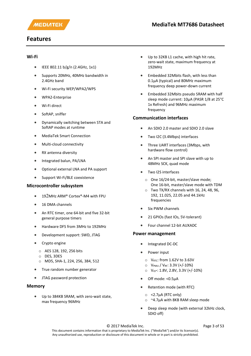
• 192MHz ARM® Cortex®-M4 with FPU
• 16 DMA channels
• An RTC timer, one 64-bit and five 32-bit
general purpose timers
• Hardware DFS from 3MHz to 192MHz
• Development support: SWD, JTAG
• Crypto engine
o AES 128, 192, 256 bits
o DES, 3DES
o MD5, SHA-1, 224, 256, 384, 512
• True random number generator
•
JTAG password protection
Memory
• Up to 384KB SRAM, with zero-wait state,
max frequency 96MHz
• Up to 32KB L1 cache, with high hit rate,
zero-wait state, maximum frequency at
192MHz
• Embedded 32Mbits flash, with less than
0.1µA (typical) and 80MHz maximum
frequency deep power-down current
• Embedded 32Mbits pseudo SRAM with half
sleep mode current: 10µA (PASR 1/8 at 25°C
1x Refresh) and 96MHz maximum
frequency
Communication interfaces
• An SDIO 2.0 master and SDIO 2.0 slave
• Two I2C (3.4Mbps) interfaces
• Three UART interfaces (3Mbps, with
hardware flow control)
• An SPI master and SPI slave with up to
48MHz SCK, quad mode
• Two I2S interfaces
o One 16/24-bit, master/slave mode;
One 16-bit, master/slave mode with TDM
o Two TX/RX channels with 16, 24, 48, 96,
192, 11.025, 22.05 and 44.1kHz
frequencies
Six PWM channels
•
• 21 GPIOs (fast IOs, 5V-tolerant)
•
Four channel 12-bit AUXADC
Power management
Integrated DC-DC
•
• Power input
o VRTC: from 1.62V to 3.63V
o VPMU / VRF: 3.3V (+/-10%)
o VIO*: 1.8V, 2.8V, 3.3V (+/-10%)
• Off mode: <0.5µA
• Retention mode (with RTC)
o <2.7µA (RTC only)
o ~4.7µA with 8KB RAM sleep mode
• Deep sleep mode (with external 32kHz clock,
SDIO off)
This document contains information that is proprietary to MediaTek Inc. (“MediaTek”) and/or its licensor(s).
Any unauthorized use, reproduction or disclosure of this document in whole or in part is strictly prohibited.
© 2017 MediaTek Inc.
Page 3 of 53
�
o 90µA with 0KB RAM sleep mode
o 118µA with 384KB RAM sleep mode
• G-band RX power: 42mA
• G-band TX power
o FPA: 248mA 19dBm CCK
o FPA: 220mA 16.5dBm OFDM
• DTIM interval with 32kHz external clock
source and 384KB SRAM
o DTIM=1: 0.63mA
o DTIM=3: 0.30mA
• Ambient temperature from -30°C to 85°C
MediaTek MT7686 Datasheet
Clock source
• 26MHz or 40MHz crystal oscillator
• 32kHz crystal oscillator or internal 32kHz RC
for RTC
Package type
• 6-mm x 6-mm x 0.9-mm 48-pin QFN with
0.4-mm lead pitch
Note:
The power consumption data is measured at 25°C.
This document contains information that is proprietary to MediaTek Inc. (“MediaTek”) and/or its licensor(s).
Any unauthorized use, reproduction or disclosure of this document in whole or in part is strictly prohibited.
© 2017 MediaTek Inc.
Page 4 of 53
�
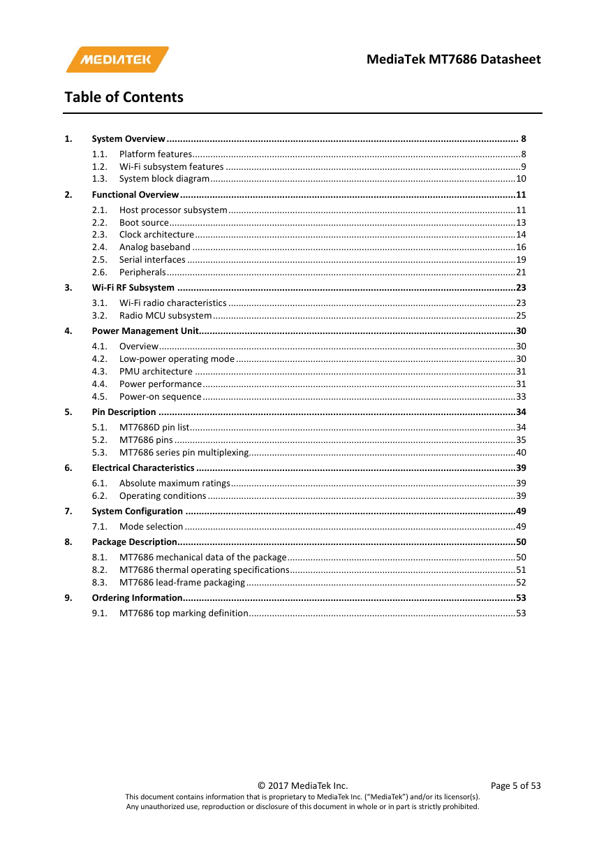
Table of Contents
MediaTek MT7686 Datasheet
4.
5.
2.
1.
System Overview ................................................................................................................................... 8
1.1. Platform features ................................................................................................................................ 8
1.2. Wi-Fi subsystem features ................................................................................................................... 9
1.3.
System block diagram ....................................................................................................................... 10
Functional Overview ............................................................................................................................. 11
2.1. Host processor subsystem ................................................................................................................ 11
2.2. Boot source ....................................................................................................................................... 13
2.3. Clock architecture ............................................................................................................................. 14
2.4. Analog baseband .............................................................................................................................. 16
2.5.
Serial interfaces ................................................................................................................................ 19
2.6. Peripherals ........................................................................................................................................ 21
3. Wi-Fi RF Subsystem .............................................................................................................................. 23
3.1. Wi-Fi radio characteristics ................................................................................................................ 23
3.2. Radio MCU subsystem ...................................................................................................................... 25
Power Management Unit...................................................................................................................... 30
4.1. Overview ........................................................................................................................................... 30
4.2.
Low-power operating mode ............................................................................................................. 30
4.3. PMU architecture ............................................................................................................................. 31
4.4. Power performance .......................................................................................................................... 31
4.5. Power-on sequence .......................................................................................................................... 33
Pin Description ..................................................................................................................................... 34
5.1. MT7686D pin list ............................................................................................................................... 34
5.2. MT7686 pins ..................................................................................................................................... 35
5.3. MT7686 series pin multiplexing........................................................................................................ 40
Electrical Characteristics ....................................................................................................................... 39
6.1. Absolute maximum ratings ............................................................................................................... 39
6.2. Operating conditions ........................................................................................................................ 39
System Configuration ........................................................................................................................... 49
7.1. Mode selection ................................................................................................................................. 49
Package Description.............................................................................................................................. 50
8.1. MT7686 mechanical data of the package ......................................................................................... 50
8.2. MT7686 thermal operating specifications ........................................................................................ 51
8.3. MT7686 lead-frame packaging ......................................................................................................... 52
Ordering Information ............................................................................................................................ 53
9.1. MT7686 top marking definition ........................................................................................................ 53
9.
6.
7.
8.
This document contains information that is proprietary to MediaTek Inc. (“MediaTek”) and/or its licensor(s).
Any unauthorized use, reproduction or disclosure of this document in whole or in part is strictly prohibited.
© 2017 MediaTek Inc.
Page 5 of 53
�
MediaTek MT7686 Datasheet
Lists of Tables and Figures
Table 2.1-1. MT7686 bus connection .................................................................................................................... 13
Table 2.4-1. Auxiliary ADC input channel .............................................................................................................. 16
Table 2.4-2. Auxiliary ADC specifications .............................................................................................................. 17
Table 2.4-3. XPLL design specifications ................................................................................................................. 18
Table 2.5-1. I2S protocol specifications ................................................................................................................ 20
Table 2.5-2. TDM protocol specifications ............................................................................................................. 20
Table 2.6-1. GPIO speeds when the Cortex-M4 cache is enabled ........................................................................ 21
Table 3.1-1. 2.4GHz RF receiver specifications ..................................................................................................... 23
Table 3.1-2. 2.4GHz RF transmitter specifications ................................................................................................ 24
Table 3.2-1. N9 memory map ............................................................................................................................... 25
Table 3.2-2. N9 interrupt source ........................................................................................................................... 28
Table 4.4-1. Current consumption in different power modes .............................................................................. 32
Table 5.1-1. MT7686D pin coordinates ................................................................................................................. 34
Table 5.2-1. Acronym for pin types and I/O structure .......................................................................................... 35
Table 5.2-2. MT7686D series pin function description and power domain .......................................................... 35
Table 5.3-1. Peripheral functions and signals ....................................................................................................... 41
Table 5.3-2. PinMux description ........................................................................................................................... 43
Table 6.1-1. Absolute maximum ratings for power supply ................................................................................... 39
Table 6.1-2. Absolute maximum ratings for I/O power supply ............................................................................. 39
Table 6.1-3. Absolute maximum ratings for voltage input ................................................................................... 39
Table 6.1-4. Absolute maximum ratings for storage temperature ....................................................................... 39
Table 6.2-1. General operating conditions............................................................................................................ 39
Table 6.2-2. Recommended operating conditions for power supply.................................................................... 40
Table 6.2-3. Recommended operating conditions for voltage input .................................................................... 40
Table 6.2-4. Recommended operating conditions for operating temperature .................................................... 40
Table 6.2-5. Electrical characteristics .................................................................................................................... 40
Table 6.2-6. ESD electrical characteristics of MT7686 series ................................................................................ 48
Table 7.1-1. Mode selection table ........................................................................................................................ 49
Table 8.2-1. MT7686 thermal operating specifications ........................................................................................ 51
Table 9.1-1. Ordering information ........................................................................................................................ 53
Figure 1.3-1. MT7686 system block diagram ........................................................................................................ 10
Figure 2.2-1. Boot source flow .............................................................................................................................. 14
Figure 2.3-1. MT7686 clock source architecture ................................................................................................... 16
Figure 2.4-1. XPLL block diagram .......................................................................................................................... 18
Figure 2.4-2. Fractional-N XPLL block diagram...................................................................................................... 19
Figure 3.1-1. 2.4GHz RF Block Diagram ................................................................................................................. 23
Figure 3.2-1. N9 bus fabric .................................................................................................................................... 27
Figure 3.2-2. N9 interrupt controller .................................................................................................................... 28
Figure 4.2-1. MT7686 Cortex-M4 and N9 power state and power mode ............................................................. 31
This document contains information that is proprietary to MediaTek Inc. (“MediaTek”) and/or its licensor(s).
Any unauthorized use, reproduction or disclosure of this document in whole or in part is strictly prohibited.
© 2017 MediaTek Inc.
Page 6 of 53
�
MediaTek MT7686 Datasheet
Figure 4.5-1. Power-on sequence ......................................................................................................................... 33
Figure 5.1-1. MT7686D pin diagram and top view ................................................................................................ 34
Figure 5.3-1. GPIO block diagram ......................................................................................................................... 40
Figure 8.1-1. Outlines and dimensions of MT7686 SQFN 6 mm x 6 mm x 0.9 mm, 48-ball package ................... 51
Figure 9.1-1. Mass production top marking of MT7686 ....................................................................................... 53
This document contains information that is proprietary to MediaTek Inc. (“MediaTek”) and/or its licensor(s).
Any unauthorized use, reproduction or disclosure of this document in whole or in part is strictly prohibited.
© 2017 MediaTek Inc.
Page 7 of 53
�
MediaTek MT7686 Datasheet
1.
System Overview
MediaTek MT7686D is a highly integrated chipset featuring an application processor, a low power 1x1 11n single-
band Wi-Fi subsystem and a power management unit (PMU).
MT7686 is based on ARM® Cortex®-M4 with floating point microcontroller unit (MCU) including 4MB PSRAM and
4MB flash memory. MT7686 also supports interfaces including UART, I2C, SPI, I2S, PWM, SDIO and ADC.
The Wi-Fi subsystem contains 802.11b/g/n radio, baseband and MAC designed to meet both low power and high
throughput application requirements. It also contains a 32-bit RISC CPU to fully offload the application processor.
1.1.
Platform features
1.1.1. Micro-controller subsystem
• ARM® Cortex®-M4 with FPU as application processor with maximum frequency at 192MHz
•
•
•
•
•
•
•
•
•
32KB L1 cache with high hit rate and zero wait state, with maximum frequency at 192MHz
384KB SYSRAM with zero wait state, with max frequency at 96MHz
SiP 32Mbits low power flash with 0.1µA deep-down current (typical condition), with maximum frequency
at 80MHz
SiP 32Mbits low power PSRAM with 10µA half-sleep mode current, with maximum frequency at 96MHz
(current condition: PASR 1/8 at 25°C single refresh)
Crypto engine that supports AES, DES/3DES, MD5, SHA1/SHA2
True random number generator
Single RTC timer, one 64-bit and five 32-bit general purpose timers (GPTs)
16 DMA channels
eXecute In Place (XIP) on flash
• Up to 21 GPIO interfaces with 5V-tolerant fast IOs, each IO can be configured as an external interrupt
source
Interfaces
1.1.2.
The following interfaces are multiplexed with GPIO.
• One SPI master interface, 1, 2 or 4-bit mode, up to 48MHz
• One SPI slave interface, 1, 2 or 4-bit mode, up to 48MHz
• One SDIO host interface (v2.0)
• One SDIO device interface (v2.0)
• One I2S interface supporting 16 or 24-bit, master or slave mode
(supports 16, 24, 48, 96, 192, 11.025, 22.05 and 44.1kHz sample rates, transmit or receive, two channels)
This document contains information that is proprietary to MediaTek Inc. (“MediaTek”) and/or its licensor(s).
Any unauthorized use, reproduction or disclosure of this document in whole or in part is strictly prohibited.
© 2017 MediaTek Inc.
Page 8 of 53
�



 2023年江西萍乡中考道德与法治真题及答案.doc
 2012年重庆南川中考生物真题及答案.doc
 2013年江西师范大学地理学综合及文艺理论基础考研真题.doc
 2020年四川甘孜小升初语文真题及答案I卷.doc
 2020年注册岩土工程师专业基础考试真题及答案.doc
 2023-2024学年福建省厦门市九年级上学期数学月考试题及答案.doc
 2021-2022学年辽宁省沈阳市大东区九年级上学期语文期末试题及答案.doc
 2022-2023学年北京东城区初三第一学期物理期末试卷及答案.doc
 2018上半年江西教师资格初中地理学科知识与教学能力真题及答案.doc
 2012年河北国家公务员申论考试真题及答案-省级.doc
 2020-2021学年江苏省扬州市江都区邵樊片九年级上学期数学第一次质量检测试题及答案.doc
 2022下半年黑龙江教师资格证中学综合素质真题及答案.doc