A Brief Introduction to Polar Codes
Supplemental Material for Advanced Channel Coding
Henry D. Pfister
April 21st, 2014
Introduction
1
Polar codes were introduced by Erdal Arıkan in 2009 and they provide the first deterministic construction
of capacity-achieving codes for binary memoryless symmetric (BMS) channels [1]. They are the culmi-
nation of Arıkan’s research (e.g., more than 20 years) into the computational cutoff rate of sequential
decoding.
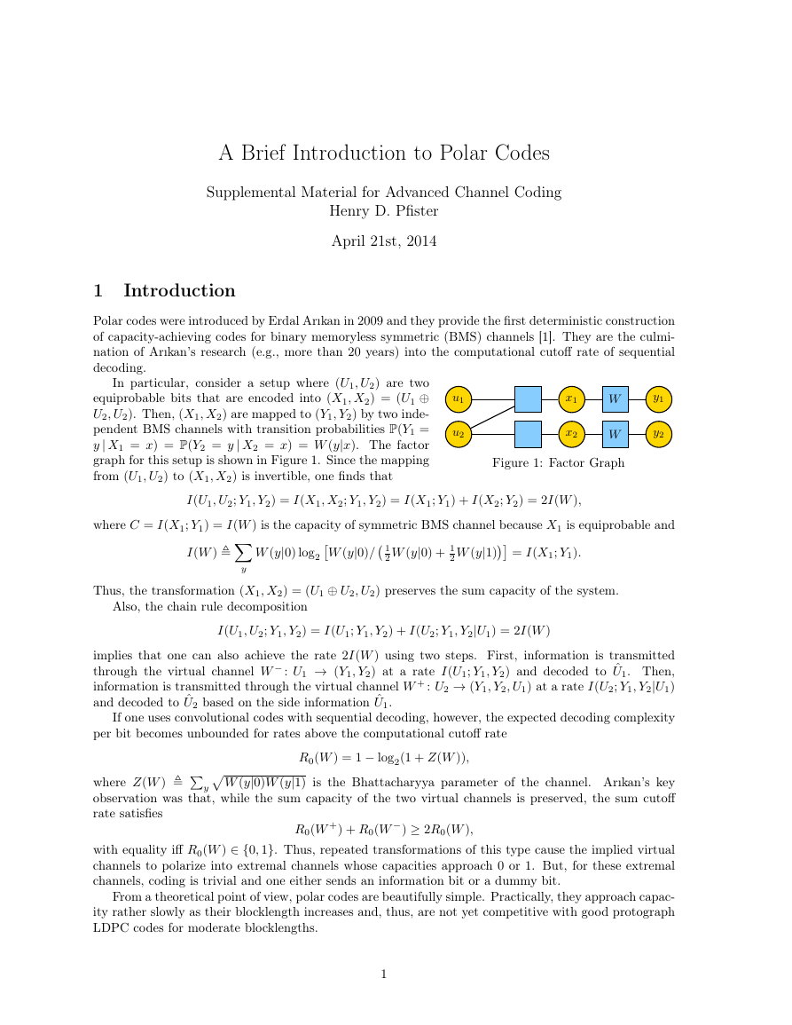
In particular, consider a setup where (U1, U2) are two
equiprobable bits that are encoded into (X1, X2) = (U1 ⊕
U2, U2). Then, (X1, X2) are mapped to (Y1, Y2) by two inde-
pendent BMS channels with transition probabilities P(Y1 =
y | X1 = x) = P(Y2 = y | X2 = x) = W (y|x). The factor
graph for this setup is shown in Figure 1. Since the mapping
from (U1, U2) to (X1, X2) is invertible, one finds that
Figure 1: Factor Graph
u1
u2
y1
y2
x1
x2
W
W
I(U1, U2; Y1, Y2) = I(X1, X2; Y1, Y2) = I(X1; Y1) + I(X2; Y2) = 2I(W ),
where C = I(X1; Y1) = I(W ) is the capacity of symmetric BMS channel because X1 is equiprobable and
I(W )
W (y|0)/ 1
W (y|0) log2
2 W (y|0) + 1
2 W (y|1) = I(X1; Y1).
y
Thus, the transformation (X1, X2) = (U1 ⊕ U2, U2) preserves the sum capacity of the system.
Also, the chain rule decomposition
I(U1, U2; Y1, Y2) = I(U1; Y1, Y2) + I(U2; Y1, Y2|U1) = 2I(W )
implies that one can also achieve the rate 2I(W ) using two steps. First, information is transmitted
through the virtual channel W − : U1 → (Y1, Y2) at a rate I(U1; Y1, Y2) and decoded to ˆU1. Then,
information is transmitted through the virtual channel W + : U2 → (Y1, Y2, U1) at a rate I(U2; Y1, Y2|U1)
and decoded to ˆU2 based on the side information ˆU1.
If one uses convolutional codes with sequential decoding, however, the expected decoding complexity
per bit becomes unbounded for rates above the computational cutoff rate
where Z(W )
y
W (y|0)W (y|1) is the Bhattacharyya parameter of the channel. Arıkan’s key
R0(W ) = 1 − log2(1 + Z(W )),
observation was that, while the sum capacity of the two virtual channels is preserved, the sum cutoff
rate satisfies
R0(W +) + R0(W −) ≥ 2R0(W ),
with equality iff R0(W ) ∈ {0, 1}. Thus, repeated transformations of this type cause the implied virtual
channels to polarize into extremal channels whose capacities approach 0 or 1. But, for these extremal
channels, coding is trivial and one either sends an information bit or a dummy bit.
From a theoretical point of view, polar codes are beautifully simple. Practically, they approach capac-
ity rather slowly as their blocklength increases and, thus, are not yet competitive with good protograph
LDPC codes for moderate blocklengths.
1
�
i=0 di2i denote the integer (indexed
from 1) with binary digit string d0d1, . . . , dn−1. Much of the following material can be found in [2]. For
matrices A = {ai,j} and B = {bi,j} , let A ⊗ B represent the Kronecker product
2 Mathematical Background
For a positive integer n, let N = 2n and let (d0d1 . . . dn−1)2 1 +n−1
a1,1B a1,2B ···
.
A ⊗ B
a2,1B a2,2B ···
...
...
...
Kronecker powers are defined by A⊗n A ⊗ A⊗n−1 = A⊗n−1 ⊗ A. The following well-known identity
will also be useful
(A ⊗ B)(C ⊗ D) = AC ⊗ BD.
An N × N permutation matrix PN satisfies P T
N PN = IN, where IN is the N × N identity matrix,
because it preserves the Euclidean distance between pairs of vectors and is therefore orthogonal. An
important permutation matrix is the “mod-p perfect shuffle” Sp,q with N = pq. Like all permutation
matrices, it is defined by where it maps the unit row vectors em for m = 1, 2, . . . , N. In particular, Sp,q
is defined by eT
m iff m = (m − 1)/p + 1 + (m − 1 mod p)q. For example, we have
m = Sp,qeT
S2,M/2(s1, s2, . . . , sM )T = (s1, s3, . . . , sM−1, s2, s4, . . . , sM )T
S3,M/3(s1, s2, . . . , sM )T = (s1, s4, . . . , sM−2, s2, s5, . . . , sM−1, s3, s6, . . . , sM )T .
Let A and B be m1 × n1 and m2 × n2 matrices, respectively. Then, mod-p perfect shuffle allows one to
write the identity
B ⊗ A = ST
m1,m2
(A ⊗ B)Sn1,n2 .
The basic idea is that A ⊗ B differs from B ⊗ A only in the order of the rows and columns and mod-p
shuffle matrices can be used to rearrange the rows and columns of A ⊗ B into those of B ⊗ A.
In
particular, if A is a 2 × 2 matrix and B is an (N/2) × (N/2) matrix, then
B ⊗ A = ST
2,N/2(A ⊗ B)S2,N/2
= RN (A ⊗ B)RT
N ,
(1)
where RN = ST
2,N/2 denotes the N × N reverse shuffle permutation matrix defined by
(s1, s2, . . . , sN )RN = (s1, s3, . . . , sN−1, s2, s4, . . . , sN ).
It is easy to verify that RN = ST
2,N/2 by transposing the previous equation.
Looking closely, we find that if m = (d0d1 . . . dn−1)2 and em = emRN, then m = (d1d2 . . . dn−1d0)2.
Therefore, RN first reorders the vector so that the base-2 expansion of the index experiences a left
circular shift. This maps the least significant bit (LSB) of the index to the most significant bit (MSB)
of the index and preserves the order of the other n − 1 bits of the index. Now, the N × N bit reversal
permutation matrix BN can be defined recursively with in terms of RN using
BN/2
0
BN = RN
0
BN/2
= RN (I2 ⊗ BN/2).
This holds because applying RN reorders the vector so that the LSB of the index becomes the MSB of
the index. Then, multiplying by I2 ⊗ BN/2 separately reorders the first and last halves of the vector
according to bit reversals of length N/2. Since BN reverses the bit indexing, it is symmetric and satisfies
BT
N = BN. Thus, we find also that
BN = BT
N =
BT
N/2
0
0
BT
N/2
RT
N =
0
BN/2
N = (I2 ⊗ BN/2)RT
RT
N .
BN/2
0
2
�
For simplicity, we will also assume that channel outputs are normalized into a posteriori probability
(APP) estimates that are either log-likelihood ratios (LLRs) or “probability of 1” (P1) values. For
example, an LLR-normalized channel output must satisfy
y1 = ln
P(Y1 = y1|X1 = 0)
P(Y1 = y1|X1 = 1)
while a P1-normalized channel output must satisfy
y1 = P(X1 = 1|Y1 = y1) =
P(Y1 = y1|X1 = 1)
P(Y1 = y1|X1 = 0) + P(Y1 = y1|X1 = 1)
.
Using this, the bit-node and check-node operations used to combine estimates in LDPC decoding are
defined, respectively, by
y1 y2 =
y1 + y2
y1y2+(1−y1)(1−y2)
y1y2
if LLR domain
if P1 domain.
and
y1 y2 =
−1 (tanh(y1/2) tanh(y2/2))
2 tanh
y1(1 − y2) + y2(1 − y1)
if LLR domain
if P1 domain.
For convenience, the operation is also defined between APP values and hard bit values so that channel
symmetry can be represented by W (y|1) = W (1 y|0). For a, b ∈ {0, 1}, we also assume that 0 y = y,
a y = y a, and a (b y) = (a ⊕ b) y.
introduction. Let (y1, y2) be a pair of normalized observations of (X1, X2). Then, ˜u1 = y1 y2 is the
optimal normalized bit estimate of U1 given (Y1, Y2). Using this, ˜u2 = (u1 y1) ˜y2 is the optimal
As an example of these operations, consider the (X1, X2) = (U1 ⊕ U2, U2) mapping defined in the
normalized bit estimate of U2 given (Y1, Y2, U1).
3 The Polar Transformation
3.1 Algebraic and Factor Graph Description
The polar transform of size N is defined to be
GN BN
1
1
⊗n
1
0
1
0
1
1
= BN G⊗n
2 ,
Since B2 = I2, one finds that
G2 =
and this transform is a fundamental building block (e.g., see Figure 1) in Arıkan’s construction of
polar codes. The main idea is to construct an message vector u where the elements ui with i ∈ A ⊆
{1, 2, . . . . , N} carry information and the other elements uj with j ∈ Ac contain values known at the
transmitter and receiver (e.g., are fixed to 0’s). Then, the codeword x = uGN is transmitted over the
channel.
Various recursive definitions of GN will also be useful. For example, the recursion BN = RN (I2 ⊗
BN/2) implies that
GN = RN (I2 ⊗ BN/2)G⊗n
2
= RN (I2 ⊗ BN/2)(G2 ⊗ G⊗n−1
= RN (G2 ⊗ BN/2G⊗n−1
= RN (G2 ⊗ GN/2)
= RN (G2 ⊗ IN/2)(I2 ⊗ GN/2).
)
2
2
)
3
�
G2
...
...
u1
u2
...
uN/2−1
uN/2
uN/2+1
uN/2+2
...
uN−1
...
...
RN
GN/2
GN/2
...
...
uN
u
·
IN/2 ⊗ G2
I2 ⊗ GN/2
=
·
·
RN
x1
x2
...
xN/2−1
xN/2
xN/2+1
xN/2+2
...
xN−1
xN
x
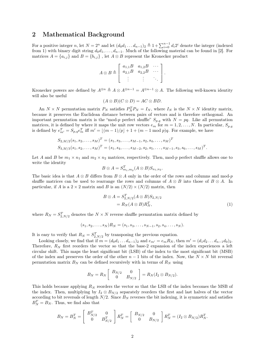
Figure 2: Factor graph associated with GN = (IN/2 ⊗ G2)RN (I2 ⊗ GN/2) decomposition.
With this result, we see that computing x = uGN is equivalent to a reverse shuffle of u followed by an
expanded G2-butterfly section and then separate polar transforms of length-N/2 applied to the first and
second halves of the vector. From (1), we know RN (G2 ⊗ IN/2)RT
N = (IN/2 ⊗ G2) and this implies that
GN = RN (G2 ⊗ IN/2)(I2 ⊗ GN/2)
= (IN/2 ⊗ G2)RN (I2 ⊗ GN/2).
The factor graph associated with this decomposition is shown Figure 2. From this, we see that computing
x = uGN using this formula is equivalent to a local G2-butterfly section followed by a reverse shuffle
and then separate polar transforms of length-N/2 applied to the first and second halves of the vector.
This representation leads naturally to the recursive encoding algorithm implied by [1] and implemented
below in Algorithm 1.
Algorithm 1 Recursive Implementation of Polar Transform in Matlab
function x = polar_transform(u)
% Recurse down to length 1
if (length(u)==1)
x = u;
else
% Compute odd/even outputs of (I_{N/2} \otimes G_2) transform
u1u2 = mod(u(1:2:end)+u(2:2:end),2);
u2 = u(2:2:end);
% R_N maps odd/even indices (i.e., u1u2/u2) to first/second half
x = [polar_transform(u1u2) polar_transform(u2)];
end
4
�
u1
u2
...
uN/2−1
uN/2
uN/2+1
uN/2+2
...
uN−1
GN/2
GN/2
RT
N
G2
...
...
...
...
x1
x2
...
xN/2−1
xN/2
xN/2+1
xN/2+2
...
xN−1
xN
x
...
...
=
uN
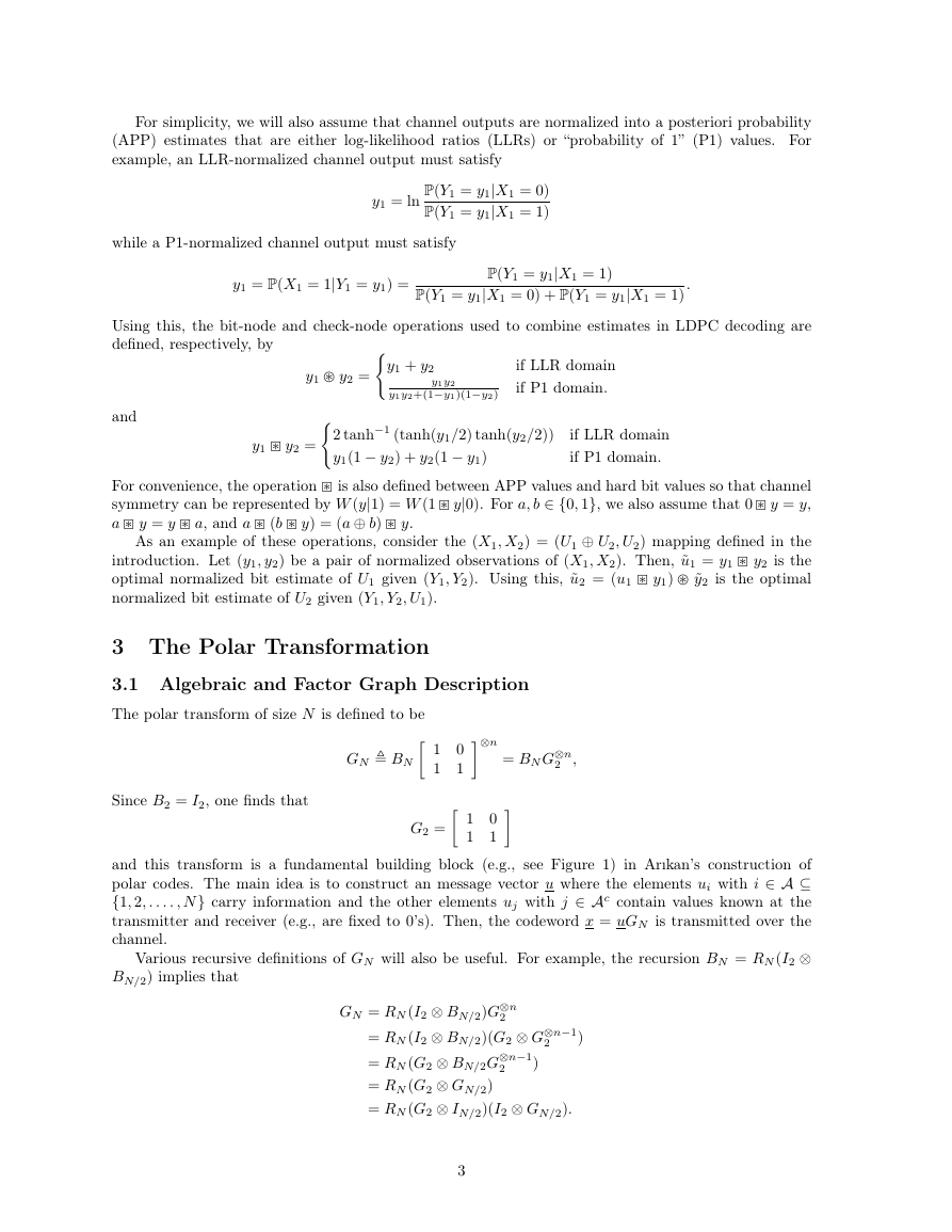
Figure 3: Factor graph associated with GN = (I2 ⊗ GN/2)RT
IN/2 ⊗ G2
I2 ⊗ GN/2
· RT
u ·
·
N
N (IN/2 ⊗ G2) decomposition.
Next, we show that BN commutes with G⊗n
IN, we use induction to show that GN BN = BN G⊗n
B2 = I2. For the inductive step, we write
2
and, hence, GN = BN G⊗n
2 = G⊗n
2 BN . Since BN BN =
2 . For N = 2, this is trivial because
2 BN = G⊗n
GN BN = BN G⊗n
2 BN
2 (I2 ⊗ BN/2)RT
2 (BN/2 ⊗ I2)RN RT
N
N
⊗ G2)(BN/2 ⊗ I2)
= RN (I2 ⊗ BN/2)G⊗n
= (BN/2 ⊗ I2)G⊗n
= (BN/2 ⊗ I2)(G⊗n−1
= ((BN/2G⊗n−1
= (BN/2G⊗n−1
⊗ G2
= G⊗n−1
2
= G⊗n
2 .
2
2
2
) ⊗ G2)(BN/2 ⊗ I2)
BN/2) ⊗ G2
Using GN = BN G⊗n
2
N, one can also get the alternative recursive decomposition
2 BN
2 (I2 ⊗ BN/2)RT
and BN = (I2⊗ BN/2)RT
GN = G⊗n
= G⊗n
= (G2 ⊗ G⊗n−1
= (G2 ⊗ (G⊗n−1
= (G2 ⊗ GN/2)RT
= (I2 ⊗ GN/2)(G2 ⊗ IN/2)RT
= (I2 ⊗ GN/2)RT
N (IN/2 ⊗ G2).
)(I2 ⊗ BN/2)RT
BN/2))RT
N
N
N
N
2
2
N
The factor graph associated with this decomposition is shown in Figure 3. From this, we see that this
decomposition is quite natural for a recursive successive-cancellation decoding algorithm because one can
5
�
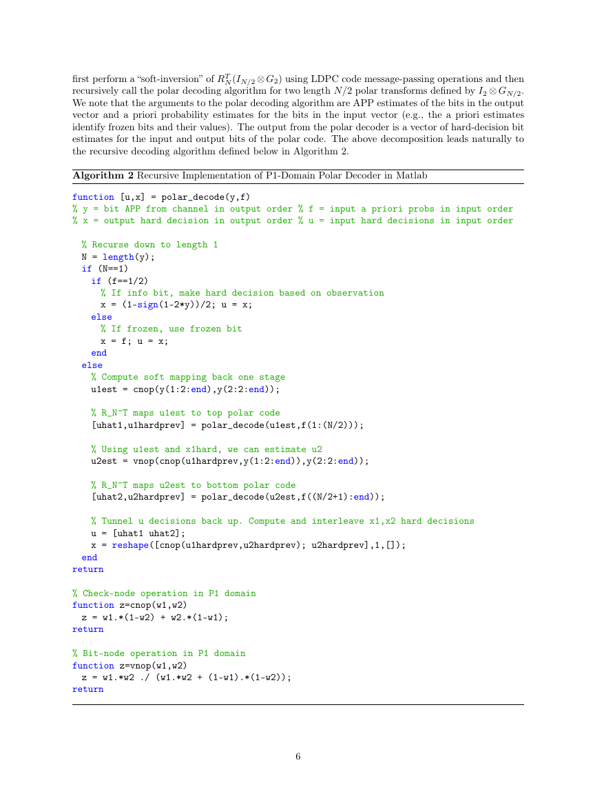
N (IN/2 ⊗ G2) using LDPC code message-passing operations and then
first perform a “soft-inversion” of RT
recursively call the polar decoding algorithm for two length N/2 polar transforms defined by I2 ⊗ GN/2.
We note that the arguments to the polar decoding algorithm are APP estimates of the bits in the output
vector and a priori probability estimates for the bits in the input vector (e.g., the a priori estimates
identify frozen bits and their values). The output from the polar decoder is a vector of hard-decision bit
estimates for the input and output bits of the polar code. The above decomposition leads naturally to
the recursive decoding algorithm defined below in Algorithm 2.
Algorithm 2 Recursive Implementation of P1-Domain Polar Decoder in Matlab
function [u,x] = polar_decode(y,f)
% y = bit APP from channel in output order % f = input a priori probs in input order
% x = output hard decision in output order % u = input hard decisions in input order
% Recurse down to length 1
N = length(y);
if (N==1)
if (f==1/2)
% If info bit, make hard decision based on observation
x = (1-sign(1-2*y))/2; u = x;
else
% If frozen, use frozen bit
x = f; u = x;
end
else
% Compute soft mapping back one stage
u1est = cnop(y(1:2:end),y(2:2:end));
% R_N^T maps u1est to top polar code
[uhat1,u1hardprev] = polar_decode(u1est,f(1:(N/2)));
% Using u1est and x1hard, we can estimate u2
u2est = vnop(cnop(u1hardprev,y(1:2:end)),y(2:2:end));
% R_N^T maps u2est to bottom polar code
[uhat2,u2hardprev] = polar_decode(u2est,f((N/2+1):end));
% Tunnel u decisions back up. Compute and interleave x1,x2 hard decisions
u = [uhat1 uhat2];
x = reshape([cnop(u1hardprev,u2hardprev); u2hardprev],1,[]);
end
return
% Check-node operation in P1 domain
function z=cnop(w1,w2)
z = w1.*(1-w2) + w2.*(1-w1);
return
% Bit-node operation in P1 domain
function z=vnop(w1,w2)
z = w1.*w2 ./ (w1.*w2 + (1-w1).*(1-w2));
return
6
�
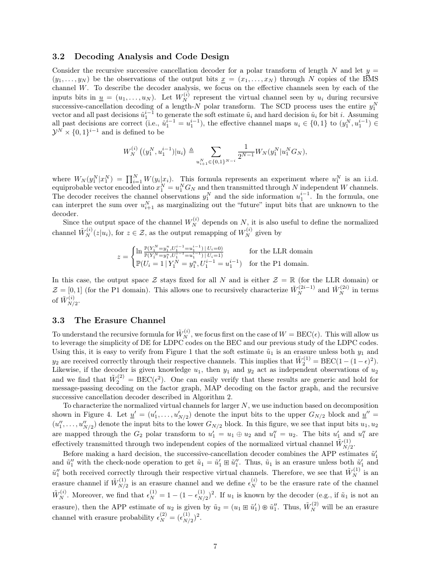
3.2 Decoding Analysis and Code Design
Consider the recursive successive cancellation decoder for a polar transform of length N and let y =
(y1, . . . , yN ) be the observations of the output bits x = (x1, . . . , xN ) through N copies of the BMS
channel W . To describe the decoder analysis, we focus on the effective channels seen by each of the
inputs bits in u = (u1, . . . , uN ). Let W (i)
N represent the virtual channel seen by ui during recursive
successive-cancellation decoding of a length-N polar transform. The SCD process uses the entire yN
1
vector and all past decisions ˆui−1
to generate the soft estimate ˜ui and hard decision ˆui for bit i. Assuming
) ∈
all past decisions are correct (i.e., ˆui−1
Y N × {0, 1}i−1 and is defined to be
), the effective channel maps ui ∈ {0, 1} to (yN
1 = ui−1
1 , ui−1
1
1
1
(yN
1 , ui−1
1
)|ui
W (i)
N
1 ) = N
i+1∈{0,1}N−i
uN
1
2N−1 WN (yN
1 |uN
1 GN ),
1 |xN
where WN (yN
equiprobable vector encoded into xN
The decoder receives the channel observations yN
can interpret the sum over uN
decoder.
i=1 W (yi|xi). This formula represents an experiment where uN
is an i.i.d.
1 GN and then transmitted through N independent W channels.
. In the formula, one
i+1 as marginalizing out the “future” input bits that are unknown to the
1 and the side information ui−1
1 = uN
1
1
Since the output space of the channel W (i)
N depends on N, it is also useful to define the normalized
channel ˜W (i)
N (z|ui), for z ∈ Z, as the output remapping of W (i)
N given by
z =
P(Y N
P(Y N
1 =yn
1 =yn
1 ,U i−1
ln
1 ,U i−1
P(Ui = 1| Y N
1 =ui−1
1 =ui−1
1 = yn
) | Ui=0)
) | Ui=1)
1 = ui−1
1 , U i−1
1
1
1
for the LLR domain
for the P1 domain.
)
In this case, the output space Z stays fixed for all N and is either Z = R (for the LLR domain) or
Z = [0, 1] (for the P1 domain). This allows one to recursively characterize ˜W (2i−1)
N in terms
of ˜W (i)
N/2.
and ˜W (2i)
N
3.3 The Erasure Channel
To understand the recursive formula for ˜W (i)
N , we focus first on the case of W = BEC(�). This will allow us
to leverage the simplicity of DE for LDPC codes on the BEC and our previous study of the LDPC codes.
Using this, it is easy to verify from Figure 1 that the soft estimate ˜u1 is an erasure unless both y1 and
2 = BEC(1− (1− �)2).
y2 are received correctly through their respective channels. This implies that ˜W (1)
Likewise, if the decoder is given knowledge u1, then y1 and y2 act as independent observations of u2
and we find that ˜W (2)
2 = BEC(�2). One can easily verify that these results are generic and hold for
message-passing decoding on the factor graph, MAP decoding on the factor graph, and the recursive
successive cancellation decoder described in Algorithm 2.
shown in Figure 4. Let u = (u
(u
1 and u
are mapped through the G2 polar transform to u
effectively transmitted through two independent copies of the normalized virtual channel ˜W (1)
N/2.
To characterize the normalized virtual channels for larger N, we use induction based on decomposition
N/2) denote the input bits to the upper GN/2 block and u =
N/2) denote the input bits to the lower GN/2 block. In this figure, we see that input bits u1, u2
1 are
1 with the check-node operation to get ˜u1 = ˜u
1. Thus, ˜u1 is an erasure unless both ˜u
and ˜u
˜u
1 both received correctly through their respective virtual channels. Therefore, we see that ˜W (1)
erasure channel if ˜W (1)
˜W (i)
Before making a hard decision, the successive-cancellation decoder combines the APP estimates ˜u
1 and
N is an
N to be the erasure rate of the channel
N/2)2. If u1 is known by the decoder (e.g., if ˜u1 is not an
N will be an erasure
erasure), then the APP estimate of u2 is given by ˜u2 = (u1 ˜u
N/2 is an erasure channel and we define �(i)
1 = u1 ⊕ u2 and u
1 ˜u
N . Moreover, we find that �(1)
1 = u2. The bits u
N = 1 − (1 − �(1)
1) ˜u
1. Thus, ˜W (2)
1 , . . . , u
1, . . . , u
1
channel with erasure probability �(2)
N = (�(1)
N/2)2.
7
�
u1
u3
...
uN−3
uN−1
u2
u4
...
uN−2
uN
uRN
...
...
·
G2
G2 ⊗ IN/2
...
...
·
GN/2
GN/2
I2 ⊗ GN/2
...
...
=
x1
x2
...
xN/2−1
xN/2
xN/2+1
xN/2+2
...
xN−1
xN
x
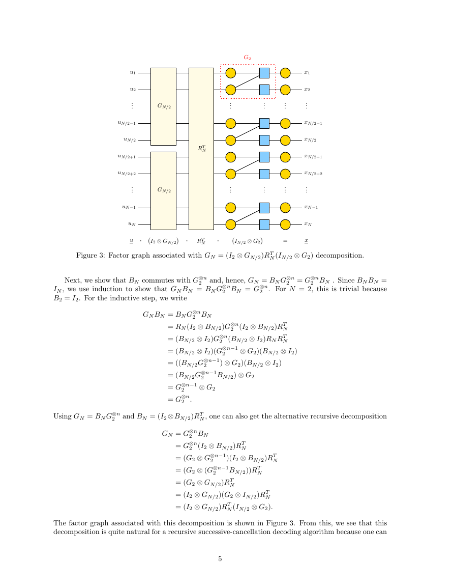
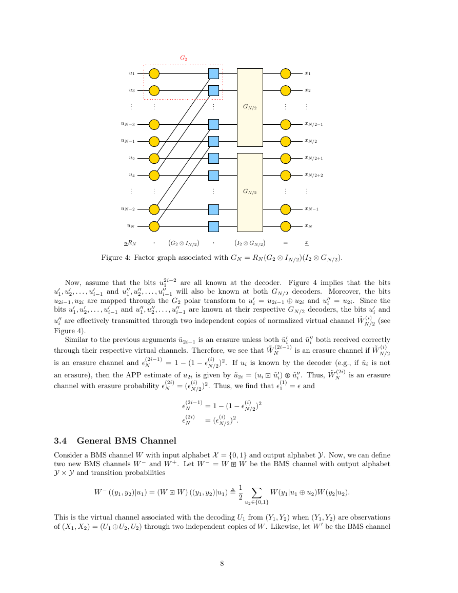
Figure 4: Factor graph associated with GN = RN (G2 ⊗ IN/2)(I2 ⊗ GN/2).
1
Now, assume that the bits u2i−2
2, . . . , u
1, u
1 , u
i−1 and u
2 , . . . , u
1 , u
i−1 and u
2, . . . , u
2 , . . . , u
are all known at the decoder. Figure 4 implies that the bits
i−1 will also be known at both GN/2 decoders. Moreover, the bits
i = u2i. Since the
i and
N/2 (see
u
1, u
u2i−1, u2i are mapped through the G2 polar transform to u
bits u
i−1 are known at their respective GN/2 decoders, the bits u
u
i are effectively transmitted through two independent copies of normalized virtual channel ˜W (i)
Figure 4).
Similar to the previous arguments ˜u2i−1 is an erasure unless both ˜u
through their respective virtual channels. Therefore, we see that ˜W (2i−1)
is an erasure channel and �(2i−1)
i both received correctly
is an erasure channel if ˜W (i)
N/2
N/2)2. If ui is known by the decoder (e.g., if ˜ui is not
N is an erasure
an erasure), then the APP estimate of u2i is given by ˜u2i = (ui ˜u
i = u2i−1 ⊕ u2i and u
i) ˜u
= 1 − (1 − �(i)
i . Thus, ˜W (2i)
i and ˜u
N
channel with erasure probability �(2i)
N/2)2. Thus, we find that �(1)
1 = � and
N
N = (�(i)
�(2i−1)
N
�(2i)
N
= 1 − (1 − �(i)
= (�(i)
N/2)2.
N/2)2
3.4 General BMS Channel
Consider a BMS channel W with input alphabet X = {0, 1} and output alphabet Y. Now, we can define
Y × Y and transition probabilities
two new BMS channels W − and W +. Let W − = W W be the BMS channel with output alphabet
W − ((y1, y2)|u1) = (W W ) ((y1, y2)|u1) 1
2
W (y1|u1 ⊕ u2)W (y2|u2).
u2∈{0,1}
This is the virtual channel associated with the decoding U1 from (Y1, Y2) when (Y1, Y2) are observations
of (X1, X2) = (U1 ⊕ U2, U2) through two independent copies of W . Likewise, let W be the BMS channel
8
�



 2023年江西萍乡中考道德与法治真题及答案.doc
 2012年重庆南川中考生物真题及答案.doc
 2013年江西师范大学地理学综合及文艺理论基础考研真题.doc
 2020年四川甘孜小升初语文真题及答案I卷.doc
 2020年注册岩土工程师专业基础考试真题及答案.doc
 2023-2024学年福建省厦门市九年级上学期数学月考试题及答案.doc
 2021-2022学年辽宁省沈阳市大东区九年级上学期语文期末试题及答案.doc
 2022-2023学年北京东城区初三第一学期物理期末试卷及答案.doc
 2018上半年江西教师资格初中地理学科知识与教学能力真题及答案.doc
 2012年河北国家公务员申论考试真题及答案-省级.doc
 2020-2021学年江苏省扬州市江都区邵樊片九年级上学期数学第一次质量检测试题及答案.doc
 2022下半年黑龙江教师资格证中学综合素质真题及答案.doc