�
Source: ANTENNA ENGINEERING HANDBOOK
P ● A ● R ● T ●
1
Introduction
and
Fundamentals
Downloaded from Digital Engineering Library @ McGraw-Hill (www.digitalengineeringlibrary.com)
Copyright © 2007 The McGraw-Hill Companies. All rights reserved.
Any use is subject to the Terms of Use as given at the website.
Introduction and Fundamentals
Downloaded from Digital Engineering Library @ McGraw-Hill (www.digitalengineeringlibrary.com)
Copyright © 2007 The McGraw-Hill Companies. All rights reserved.
Any use is subject to the Terms of Use as given at the website.
�
Source: ANTENNA ENGINEERING HANDBOOK
Chapter 1
Fundamentals
of Antennas,
Arrays, and Mobile
Communications
Thomas F. Eibert
Universität Stuttgart
John L. Volakis
The Ohio State University
CONTENTS
1.1
INTRODUCTION . . . . . . . . . . . . . . . . . . . . . . . . . . . . . . . . . . . . . . . . . . 1-4
1.2 HUYGENS’ AND EQUIVALENCE PRINCIPLES. . . . . . . . . . . . . . . . . . 1-5
1.3 HERTZIAN AND FITZGERALD ELEMENTARY RADIATORS . . . . . . . 1-7
1.4
FAR-FIELD ANTENNA PROPERTIES, POWER TRANSFER,
AND RECIPROCITY. . . . . . . . . . . . . . . . . . . . . . . . . . . . . . . . . . . . . . . . 1-8
1.5 ANTENNAS AS ELECTROMAGNETIC CIRCUITS. . . . . . . . . . . . . . . 1-11
1.6 POLARIZATION. . . . . . . . . . . . . . . . . . . . . . . . . . . . . . . . . . . . . . . . . . 1-14
1.7
1.8
DIRECTIVITY PATTERNS FROM CONTINUOUS
LINE SOURCES. . . . . . . . . . . . . . . . . . . . . . . . . . . . . . . . . . . . . . . . . . 1-17
DIRECTIVITY PATTERNS FROM AREA
SOURCE DISTRIBUTIONS. . . . . . . . . . . . . . . . . . . . . . . . . . . . . . . . . 1-21
1.9 FUNDAMENTALS OF ANTENNA ARRAYS . . . . . . . . . . . . . . . . . . . . 1-27
1.10 BASIC CONCEPTS IN MOBILE COMMUNICATIONS . . . . . . . . . . . 1-32
1-3
Downloaded from Digital Engineering Library @ McGraw-Hill (www.digitalengineeringlibrary.com)
Copyright © 2007 The McGraw-Hill Companies. All rights reserved.
Any use is subject to the Terms of Use as given at the website.
�
Fundamentals of Antennas, Arrays, and Mobile Communications
1-4
CHAPTER ONE
1.1
INTRODUCTION *
Antennas are key components of any wireless communication system.1,2 They are the
devices that allow for the transfer of a signal (in a wired system) to waves that, in turn,
propagate through space and can be received by another antenna. The receiving antenna
is responsible for the reciprocal process, i.e., that of turning an electromagnetic wave into
a signal or voltage at its terminals that can subsequently be processed by the receiver. The
receiving and transmitting functionalities of the antenna structure itself are fully char-
acterized by Maxwell’s equations and are fairly well understood.3 The dipole antenna
(a straight wire, fed at the center by a two-wire transmission line) was the first antenna ever
used and is also one of the best understood.1,2 For effective reception and transmission, it must
be approximately l/2 long (l = wavelength) at the frequency of operation (or multiples of
this length). Thus, it must be fairly long (or high) when used at low frequencies (l = 1 m at
300 MHz), and even at higher frequencies (UHF and greater), its protruding nature makes it
quite undesirable. Further, its low gain (2.15 dB), lack of directionality, and extremely narrow
bandwidth make it even less attractive. Not surprisingly, the Yagi-Uda antenna (typically seen
on the roof of most houses for television reception) was considered a breakthrough in antenna
technology when introduced in the early 1920s because of its much higher gain of 8–14 dB.
Log-periodic wire antennas introduced in the late 1950s and 1960s and wire spirals allowed
for both gain and bandwidth increases. On the other hand, even today high gain antennas rely
on large reflectors (dish antennas) and waveguide arrays (used for many radar systems).
Until the late 1970s, antenna design was based primarily on practical approaches using
off-the-shelf antennas such as various wire geometries (dipoles, Yagi-Uda, log-periodics,
spirals), horns, reflectors, and slots/apertures as well as arrays of some of these. The antenna
engineer could choose or modify one of them based on design requirements that characterize
antennas, such as gain, input impedance, bandwidth, pattern beamwidth, and sidelobe
levels (see References 4 and 5 for a description of these quantities). Antenna development
required extensive testing and experimentation and was, therefore, funded primarily by
governments. However, in recent years, dramatic growth in computing speed and develop-
ment of effective computational techniques for realistic antenna geometries has allowed for
low-cost virtual antenna design. Undoubtedly, the explosive growth of wireless communi-
cations and microwave sensors, microwave imaging needs, and radars has been the catalyst
for introducing a multitude of new antenna designs over the past decade and an insatiable
desire for using modern computational techniques for low-cost designs. Requirements for
∗Heinrich R. Hertz was the first to demonstrate the generation of radio waves at UHF using a gap dipole in 1885–
1886 at Karlsruhe University (Germany). Hertz was able to detect radio waves 20 m away using a high-voltage
electrical spark discharge to excite the dipole gap. From recorded conversations, Hertz did not seem to understand
the impact of his experiments, but instead did it as a validation of the newly developed Maxwell’s equations. Within
ten years, Tesla at the Franklin Institute in the U.S., Marconi in Bologna, Italy, Popov in Russia, and Bose in India,
demonstrated wireless telegraphy. In 1892, Tesla delivered a widely distributed presentation at the IRE of London
about “transmitting intelligence without wires,” and in 1895, he transmitted signals detected 50 miles (80 km) away.
Concurrently, in 1894 Bose used wireless signals to ring a bell in Calcutta, and Popov presented his radio receiver
to the Russian Physical & Chemical Society on May 7, 1895. Marconi is certainly considered the key individual for
his contributions to the commercialization of radio waves, and he received the Nobel prize for his work in 1909.
Nevertheless, Marconi’s widely advertised first radio wave transmission experiment was in 1895, and his British pat-
ent application in 1897 was preceded by that of Tesla. A culmination of Marconi’s experiments was the December 12,
1901, trans-Atlantic radio wave transmission of the Morse code for the letter S. The success of this experiment is often
disputed, possibly due to strong atmospheric noise during the time of the experiment, but by the 1920s the U.S. had
hundreds of radio stations, and in 1922, the BBC began transmitting in England. Subsequent development of radio
detectors, vacuum tubes, and the tiny transistor in 1947 played a critical role in the practical everyday use of radio
waves for communication and wireless transmission of information.
Downloaded from Digital Engineering Library @ McGraw-Hill (www.digitalengineeringlibrary.com)
Copyright © 2007 The McGraw-Hill Companies. All rights reserved.
Any use is subject to the Terms of Use as given at the website.
�
Fundamentals of Antennas, Arrays, and Mobile Communications
FUNDAMENTALS OF ANTENNAS, ARRAYS, AND MOBILE COMMUNICATIONS
1-5
conformal antennas (non-protruding) for airborne systems, increased bandwidth require-
ments, and multifunctionality have led to heavy exploitation of printed (patch) or other
slot-type antennas4 and the use of powerful computational tools (commercial and noncom-
mercial) for designing such antennas.
Needless to say, the commercial mobile communications industry has been the catalyst
for the recent explosive growth in antenna design needs. Certainly, the past decade has seen
an extensive use of antennas by the public for cellular, GPS, satellite, wireless LAN for
computers (WiFi), Bluetooth technology, Radio Frequency ID (RFID) devices, WiMAX,
and so on. However, future needs will be even greater when a multitude of antennas are
integrated into say automobiles for all sorts of communication needs and into a variety of
portable devices and sensors for monitoring and information gathering. Certainly, future
RFID devices will most likely replace the bar codes on all products while concurrently
allowing for instantaneous inventorying. For military applications, there is an increasing
need for small and conformal multifunctional antennas that can satisfy a plethora of com-
munications needs using as little space as possible.
In this first chapter of the handbook, we provide a summary of antenna fundamen-
tals and introduce antenna parameters typically used for characterizing antenna properties
often employed to evaluate the entire radio system. We start with the radiation of an ideal
(Hertzian) or infinitesimal dipole and proceed to the resonant l/2 dipole, antenna arrays,
and mobile communication concepts.
1.2 HUYGENS’ AND EQUIVALENCE PRINCIPLES
The electromagnetic behavior and thus the functioning of antennas is governed by
Maxwell’s equations,3 which must be solved for a particular antenna and a given excita-
tion. Typically, exact solutions of Maxwell’s equations are not available and thus numerical
modeling is often used to compute approximate solutions for practical configurations. A
formal simplification of electromagnetic antenna problems can be achieved by employing
the equivalence principle.3 If interest is restricted to the field solution in a limited region of
space, the antenna configuration can be replaced by the equivalent electromagnetic sources
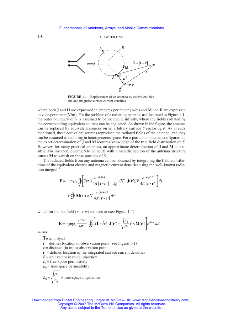
located on the surface of a volume enclosing the antenna configuration (see Figure 1-1).
Because the antenna materials are no longer there, these sources are usually radiating in a
homogeneous solution space (such as free-space), and the corresponding fields can thus be
calculated by evaluating the radiation integrals.
The equivalent sources are not uniquely defined, and there are many different ways of
constructing them. In general, the equivalent sources are a composition of electric and mag-
netic surface current densities representing the excitation terms in Maxwell’s equations. A
straightforward way of constructing equivalent sources is provided by Huygens’ principle.3
Huygens’ principle states that the field solution in a region V is completely determined by
the tangential fields over the surface S enclosing V. The corresponding electric and mag-
netic equivalent surface current densities are given by
Electric current density:
Magnetic current density:
J
= ˆn ×
H
M
= − ׈n
E
(1-1)
(1-2)
Downloaded from Digital Engineering Library @ McGraw-Hill (www.digitalengineeringlibrary.com)
Copyright © 2007 The McGraw-Hill Companies. All rights reserved.
Any use is subject to the Terms of Use as given at the website.
�
Fundamentals of Antennas, Arrays, and Mobile Communications
1-6
CHAPTER ONE
n
S
R = r − r
r
M
z
y
J
r
x
FIGURE 1-1 Replacement of an antenna by equivalent elec-
tric and magnetic surface current densities
where both J and H are expressed in amperes per meter (A/m) and M and E are expressed
in volts per meter (V/m). For the problem of a radiating antenna, as illustrated in Figure 1-1,
the outer boundary of V is assumed to be located at infinity, where the fields radiated by
the corresponding equivalent sources can be neglected. As shown in the figure, the antenna
can be replaced by equivalent sources on an arbitrary surface S enclosing it. As already
mentioned, these equivalent sources reproduce the radiated fields of the antenna, and they
can be assumed as radiating in homogeneous space. For a particular antenna configuration,
the exact determination of J and M requires knowledge of the true field distribution on S.
However, for many practical antennas, an approximate determination of J and M is pos-
sible. For instance, placing S to coincide with a metallic section of the antenna structure
causes M to vanish on these portions of S.
The radiated fields from any antenna can be obtained by integrating the field contribu-
tions of the equivalent electric and magnetic current densities using the well-known radia-
tion integral:3
E
= −
ωµ
j
0
J
∫∫
S
r
( ')
−
j
e k
π
|
4
r-r
|
'|
0
r - r
+
' |
1
2
k
0
(
∇ ⋅
'
J r
(
''))
∇
−
e
π
4
'|
r-r
|
j 0
k
r - r
|
' |
ds
'
+
∫∫
M r
( ')
× ∇
−e
r-r
'|
|
r - rπ
4
kj 0
|
' |
ds
'
which for the far-field (r → ∞) reduces to (see Figure 1-1)
E
= −
where
j
k r
0
−
e
ωµ π
j
4
r
0
∫∫
(
I
−
ˆˆ)
rr
⋅
J r
( ')
−
ε
0
µ
0
ˆ
r
×
M r
( ')
krj ˆ
⋅
r
'
e
ds
'
I = unit dyad
r = defines location of observation point (see Figure 1-1)
r = distance (in m) to observation point
r' = defines location of the integrated surface current densities
ˆr = unit vector in radial direction
e0 = free-space permittivity
m0 = free-space permeability
Z0 =
µ
0
ε
0
= free-space impedance
Downloaded from Digital Engineering Library @ McGraw-Hill (www.digitalengineeringlibrary.com)
Copyright © 2007 The McGraw-Hill Companies. All rights reserved.
Any use is subject to the Terms of Use as given at the website.
�
Fundamentals of Antennas, Arrays, and Mobile Communications
FUNDAMENTALS OF ANTENNAS, ARRAYS, AND MOBILE COMMUNICATIONS
1-7
0
=ωµ
0
k Z0
k0 = b = 2p /l
l = wavelength (in meters, m)
j = −1
E is given in volts per meter (V/m)
H is given in amperes per meter (A/m)
For the ideal (delta) or infinitesimal electric (Hertzian) or magnetic (Fitzgerald) dipole
sources, the radiation integrals are eliminated and the fields can be given in closed forms. The
resulting field expressions can then be used to extract and study the usual antenna parameters.
1.3 HERTZIAN AND FITZGERALD
ELEMENTARY RADIATORS
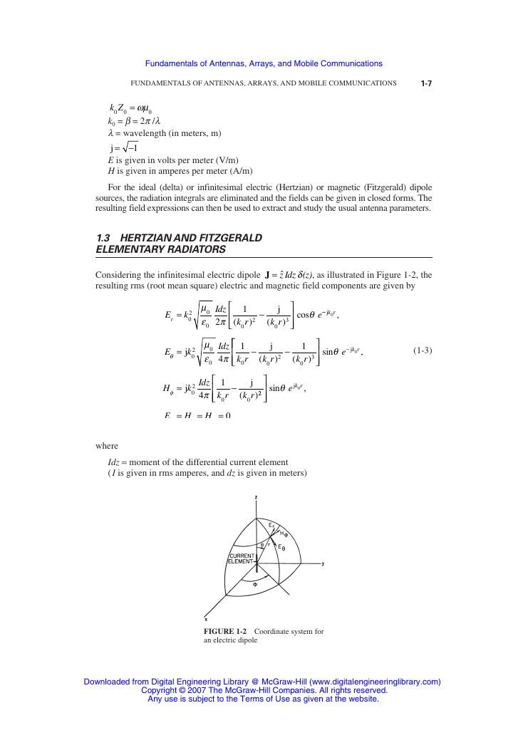
Considering the infinitesimal electric dipole J = ˆz Idz (z)δ , as illustrated in Figure 1-2, the
resulting rms (root mean square) electric and magnetic field components are given by
r =
E
k
2
0
µ
Idz
0
ε π
2
0
E
θ
=
j
k
2
0
µ
Idz
0
ε π
4
0
(
1
k r
0
2
)
−
j
k r
0
(
3
)
cos
θ
e
−−
j
k r
0
,
1
k r
0
−
j
k r
0
(
2
)
−
1
k r
0
(
3
)
sin
−
jθ
e
k r0
H
φ
=
j
k
2
0
Idz
π
4
1
k r
0
−
j
k r
0
(
)22
E
φ
=
H
r
=
H
θ
=
0
where
sin
jθ
e
k r
0
,
(1-3)
,
Idz = moment of the differential current element
( I is given in rms amperes, and dz is given in meters)
FIGURE 1-2 Coordinate system for
an electric dipole
Downloaded from Digital Engineering Library @ McGraw-Hill (www.digitalengineeringlibrary.com)
Copyright © 2007 The McGraw-Hill Companies. All rights reserved.
Any use is subject to the Terms of Use as given at the website.
�




 2023年江西萍乡中考道德与法治真题及答案.doc
 2012年重庆南川中考生物真题及答案.doc
 2013年江西师范大学地理学综合及文艺理论基础考研真题.doc
 2020年四川甘孜小升初语文真题及答案I卷.doc
 2020年注册岩土工程师专业基础考试真题及答案.doc
 2023-2024学年福建省厦门市九年级上学期数学月考试题及答案.doc
 2021-2022学年辽宁省沈阳市大东区九年级上学期语文期末试题及答案.doc
 2022-2023学年北京东城区初三第一学期物理期末试卷及答案.doc
 2018上半年江西教师资格初中地理学科知识与教学能力真题及答案.doc
 2012年河北国家公务员申论考试真题及答案-省级.doc
 2020-2021学年江苏省扬州市江都区邵樊片九年级上学期数学第一次质量检测试题及答案.doc
 2022下半年黑龙江教师资格证中学综合素质真题及答案.doc