3GPP TR 38.901 V14.3.0 (2017-12)
Technical Report
3rd Generation Partnership Project;
Technical Specification Group Radio Access Network;
Study on channel model for frequencies from 0.5 to 100 GHz
(Release 14)
The present document has been developed within the 3rd Generation Partnership Project (3GPP TM) and may be further elaborated for the purposes of 3GPP.
The present document has not been subject to any approval process by the 3GPP Organizational Partners and shall not be implemented.
This Report is provided for future development work within 3GPP only. The Organizational Partners accept no liability for any use of this Specification.
Specifications and Reports for implementation of the 3GPP TM system should be obtained via the 3GPP Organizational Partners' Publications Offices.
�
Release 14
2
3GPP TR 38.901 V14.3.0 (2017-12)
Keywords
New Radio
3GPP
Postal address
3GPP support office address
650 Route des Lucioles - Sophia Antipolis
Valbonne - FRANCE
Tel.: +33 4 92 94 42 00 Fax: +33 4 93 65 47 16
Internet
http://www.3gpp.org
Copyright Notification
No part may be reproduced except as authorized by written permission.
The copyright and the foregoing restriction extend to reproduction in all media.
© 2017, 3GPP Organizational Partners (ARIB, ATIS, CCSA, ETSI, TSDSI, TTA, TTC).
All rights reserved.
UMTS™ is a Trade Mark of ETSI registered for the benefit of its members
3GPP™ is a Trade Mark of ETSI registered for the benefit of its Members and of the 3GPP Organizational Partners
LTE™ is a Trade Mark of ETSI registered for the benefit of its Members and of the 3GPP Organizational Partners
GSM® and the GSM logo are registered and owned by the GSM Association
3GPP
�
Release 14
3
3GPP TR 38.901 V14.3.0 (2017-12)
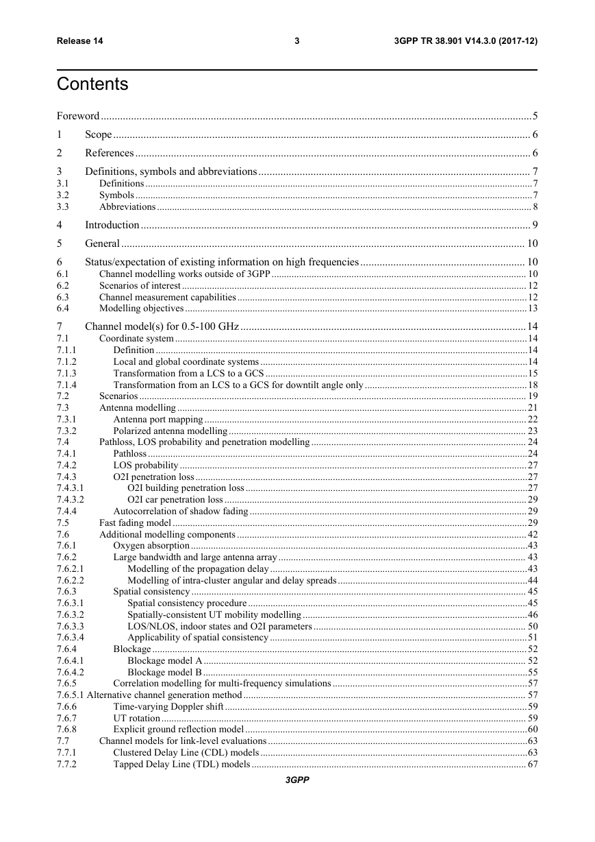
Contents
Foreword.............................................................................................................................................................5
1
Scope........................................................................................................................................................ 6
References................................................................................................................................................ 6
2
Definitions, symbols and abbreviations................................................................................................... 7
3
3.1
Definitions...........................................................................................................................................................7
Symbols...............................................................................................................................................................7
3.2
Abbreviations...................................................................................................................................................... 8
3.3
4
Introduction.............................................................................................................................................. 9
General................................................................................................................................................... 10
5
Status/expectation of existing information on high frequencies............................................................ 10
6
Channel modelling works outside of 3GPP...................................................................................................... 10
6.1
6.2
Scenarios of interest.......................................................................................................................................... 12
Channel measurement capabilities....................................................................................................................12
6.3
Modelling objectives.........................................................................................................................................13
6.4
7
Channel model(s) for 0.5-100 GHz........................................................................................................14
Coordinate system .............................................................................................................................................14
7.1
Definition .....................................................................................................................................................14
7.1.1
Local and global coordinate systems ...........................................................................................................14
7.1.2
Transformation from a LCS to a GCS .........................................................................................................15
7.1.3
7.1.4
Transformation from an LCS to a GCS for downtilt angle only .................................................................18
Scenarios........................................................................................................................................................... 19
7.2
Antenna modelling ............................................................................................................................................21
7.3
Antenna port mapping ................................................................................................................................. 22
7.3.1
7.3.2
Polarized antenna modelling....................................................................................................................... 23
Pathloss, LOS probability and penetration modelling ...................................................................................... 24
7.4
Pathloss........................................................................................................................................................24
7.4.1
LOS probability ...........................................................................................................................................27
7.4.2
7.4.3
O2I penetration loss.....................................................................................................................................27
O2I building penetration loss.................................................................................................................27
7.4.3.1
O2I car penetration loss ......................................................................................................................... 29
7.4.3.2
7.4.4
Autocorrelation of shadow fading ...............................................................................................................29
Fast fading model..............................................................................................................................................29
7.5
7.6
Additional modelling components .................................................................................................................... 42
Oxygen absorption.......................................................................................................................................43
7.6.1
Large bandwidth and large antenna array................................................................................................... 43
7.6.2
Modelling of the propagation delay.......................................................................................................43
7.6.2.1
7.6.2.2
Modelling of intra-cluster angular and delay spreads............................................................................44
Spatial consistency ...................................................................................................................................... 45
7.6.3
Spatial consistency procedure................................................................................................................45
7.6.3.1
Spatially-consistent UT mobility modelling ..........................................................................................46
7.6.3.2
7.6.3.3
LOS/NLOS, indoor states and O2I parameters ..................................................................................... 50
Applicability of spatial consistency.......................................................................................................51
7.6.3.4
Blockage ......................................................................................................................................................52
7.6.4
Blockage model A................................................................................................................................. 52
7.6.4.1
7.6.4.2
Blockage model B..................................................................................................................................55
7.6.5
Correlation modelling for multi-frequency simulations ..............................................................................57
7.6.5.1 Alternative channel generation method................................................................................................................. 57
Time-varying Doppler shift .........................................................................................................................59
7.6.6
UT rotation.................................................................................................................................................. 59
7.6.7
7.6.8
Explicit ground reflection model.................................................................................................................60
Channel models for link-level evaluations ........................................................................................................63
7.7
Clustered Delay Line (CDL) models...........................................................................................................63
7.7.1
7.7.2
Tapped Delay Line (TDL) models.............................................................................................................. 67
3GPP
�
Release 14
4
3GPP TR 38.901 V14.3.0 (2017-12)
7.7.3
7.7.4
7.7.4.1
7.7.4.2
7.7.5
7.7.5.1
7.7.5.2
7.7.6
7.8
7.8.1
7.8.2
7.8.3
8
8.1
8.2
8.3
8.4
Annex A:
A.1
A.2
Annex B:
Scaling of delays ..........................................................................................................................................70
Spatial filter for generating TDL channel model........................................................................................ 71
Exemplary filters/antenna patterns........................................................................................................ 71
Generation procedure.............................................................................................................................72
Extension for MIMO simulations ................................................................................................................72
CDL extension: Scaling of angles......................................................................................................... 72
TDL extension: Applying a correlation matrix ......................................................................................73
K-factor for LOS channel models............................................................................................................... 74
Channel model calibration................................................................................................................................ 74
Large scale calibration.................................................................................................................................74
Full calibration.............................................................................................................................................75
Calibration of additional features................................................................................................................ 76
Map-based hybrid channel model (Alternative channel model methodology)...................................... 78
Coordinate system .............................................................................................................................................78
Scenarios........................................................................................................................................................... 78
Antenna modelling ............................................................................................................................................78
Channel generation............................................................................................................................................78
Further parameter definitions.............................................................................................89
Calculation of angular spread............................................................................................................................89
Calculation of mean angle .................................................................................................................................89
Change history...................................................................................................................... 90
3GPP
�
Release 14
5
3GPP TR 38.901 V14.3.0 (2017-12)
Foreword
This Technical Report has been produced by the 3rd Generation Partnership Project (3GPP).
The contents of the present document are subject to continuing work within the TSG and may change following formal
TSG approval. Should the TSG modify the contents of the present document, it will be re-released by the TSG with an
identifying change of release date and an increase in version number as follows:
Version x.y.z
where:
x the first digit:
1 presented to TSG for information;
2 presented to TSG for approval;
3 or greater indicates TSG approved document under change control.
y the second digit is incremented for all changes of substance, i.e. technical enhancements, corrections, updates,
etc.
z
the third digit is incremented when editorial only changes have been incorporated in the document.
3GPP
�
Release 14
6
3GPP TR 38.901 V14.3.0 (2017-12)
Scope
1
The present document captures the findings of the study item, "Study on channel model for frequency spectrum above 6
GHz" [2] and from further findings of the study item, "Study on New Radio Access Technology [22]." The channel
models in the present document address the frequency range 0.5-100 GHz. The purpose of this TR is to help TSG RAN
WG1 to properly model and evaluate the performance of physical layer techniques using the appropriate channel
model(s). Therefore, the TR will be kept up-to-date via CRs in the future.
This document relates to the 3GPP evaluation methodology and covers the modelling of the physical layer of both
Mobile Equipment and Access Network of 3GPP systems.
This document is intended to capture the channel model(s) for frequencies from 0.5GHz up to 100GHz.
References
2
The following documents contain provisions which, through reference in this text, constitute provisions of the present
document.
- References are either specific (identified by date of publication, edition number, version number, etc.) or
non- specific.
- For a specific reference, subsequent revisions do not apply.
- For a non-specific reference, the latest version applies. In the case of a reference to a 3GPP document (including
a GSM document), a non-specific reference implicitly refers to the latest version of that document in the same
Release as the present document.
[1]
[2]
[3]
[4]
[5]
[6]
[7]
[8]
[9]
[10]
[11]
[12]
[13]
[14]
3GPP TR 21.905: "Vocabulary for 3GPP Specifications".
3GPP TD RP-151606: "Study on channel model for frequency spectrum above 6 GHz".
3GPP TR 36.873 (V12.2.0): "Study on 3D channel model for LTE".
3GPP RP-151847: "Report of RAN email discussion about >6GHz channel modelling", Samsung.
3GPP TD R1-163408: "Additional Considerations on Building Penetration Loss Modelling for 5G
System Performance Evaluation", Straight Path Communications.
ICT-317669-METIS/D1.4: "METIS channel model, METIS 2020, Feb, 2015".
Glassner, A S: "An introduction to ray tracing. Elsevier, 1989".
McKown, J. W., Hamilton, R. L.: "Ray tracing as a design tool for radio networks, Network, IEEE,
1991(6): 27-30".
Kurner, T., Cichon, D. J., Wiesbeck, W.: "Concepts and results for 3D digital terrain-based wave
propagation models: An overview", IEEE J.Select. Areas Commun., vol. 11, pp. 1002–1012, 1993.
Born, M., Wolf, E.: "Principles of optics: electromagnetic theory of propagation, interference and
diffraction of light", CUP Archive, 2000.
Friis, H.: "A note on a simple transmission formula", proc. IRE, vol. 34, no. 5, pp. 254–256, 1946.
Kouyoumjian, R.G., Pathak, P.H.: "A uniform geometrical theory of diffraction for an edge in a
perfectly conducting surface" Proc. IEEE, vol. 62, pp. 1448–1461, Nov. 1974.
Pathak, P.H., Burnside, W., Marhefka, R.: "A Uniform GTD Analysis of the Diffraction of
Electromagnetic Waves by a Smooth Convex Surface", IEEE Transactions on Antennas and
Propagation, vol. 28, no. 5, pp. 631–642, 1980.
IST-WINNER II Deliverable 1.1.2 v.1.2, "WINNER II Channel Models", IST-WINNER2, Tech.
Rep., 2007 (http://www.ist-winner.org/deliverables.html).
3GPP
�
Release 14
7
3GPP TR 38.901 V14.3.0 (2017-12)
[15]
[16]
[17]
[18]
[19]
[20]
[21]
[22]
3GPP TR36.101: "User Equipment (UE) radio transmission and reception".
3GPP TR36.104: "Base Station (BS) radio transmission and reception".
Asplund, H., Medbo, J., Göransson, B., Karlsson, J., Sköld, J.: "A simplified approach to applying
the 3GPP spatial channel model", in Proc. of PIMRC 2006.
ITU-R Rec. P.1816: "The prediction of the time and the spatial profile for broadband land mobile
services using UHF and SHF bands".
ITU-R Rec. P.2040-1: "Effects of building materials and structures on radiowave propagation
above about 100 MHz", International Telecommunication Union Radiocommunication Sector
ITU-R, 07/2015.
ITU-R Rec. P.527-3: "Electrical characteristics of the surface of the earth", International
Telecommunication Union Radiocommunication Sector ITU-R, 03/1992.
Jordan, E.C., Balmain, K.G.: "Electromagnetic Waves and Radiating Systems", Prentice-Hall Inc.,
1968.
3GPP TD RP-162469: "Study on New Radio (NR) Access Technology".
3
Definitions, symbols and abbreviations
Definitions
3.1
For the purposes of the present document, the terms and definitions given in TR 21.905 [1] apply.
Symbols
3.2
For the purposes of the present document, the following symbols apply:
A
maxA
d2D
d3D
Hd
Vd
f
fc
Frx,u,θ
Frx,u,ϕ
Ftx,s,θ
Frx,s,ϕ
hBS
hUT
,ˆ
mnrxr
,
,ˆ
mntxr
,
lgASA
antenna radiation power pattern
maximum attenuation
2D distance between Tx and Rx
3D distance between Tx and Rx
antenna element spacing in horizontal direction
antenna element spacing in vertical direction
frequency
center frequency / carrier frequency
Receive antenna element u field pattern in the direction of the spherical basis vector ˆ
Receive antenna element u field pattern in the direction of the spherical basis vector ˆ
Transmit antenna element s field pattern in the direction of the spherical basis vector ˆ
Transmit antenna element s field pattern in the direction of the spherical basis vector ˆ
antenna height for BS
antenna height for UT
spherical unit vector of cluster n, ray m, for receiver
spherical unit vector of cluster n, ray m, for transmitter
bearing angle
downtilt angle
slant angle
wavelength
cross-polarization power ratio in linear scale
mean value of 10-base logarithm of azimuth angle spread of arrival
3GPP
�
Release 14
8
3GPP TR 38.901 V14.3.0 (2017-12)
lgASD
lgDS
lgZSA
lgZSD
LOSPr
SLA
V
lgASA
lgASD
lgDS
lgZSA
lgZSD
SF
ˆ
ˆ
3dB
ˆ
ˆ
etilt
3dB
mean value of 10-base logarithm of azimuth angle spread of departure
mean value of 10-base logarithm of delay spread
mean value of 10-base logarithm of zenith angle spread of arrival
mean value of 10-base logarithm of zenith angle spread of departure
LOS probability
side-lobe attenuation in vertical direction
standard deviation of 10-base logarithm of azimuth angle spread of arrival
standard deviation of 10-base logarithm of azimuth angle spread of departure
standard deviation value of 10-base logarithm of delay spread
standard deviation of 10-base logarithm of zenith angle spread of arrival
standard deviation of 10-base logarithm of zenith angle spread of departure
standard deviation of SF
azimuth angle
zenith angle
spherical basis vector (unit vector) for GCS
spherical basis vector (unit vector) for LCS
horizontal 3 dB beamwidth of an antenna
spherical basis vector (unit vector), orthogonal to ˆ, for GCS
spherical basis vector (unit vector), orthogonal to ˆ , for LCS
electrical steering angle in vertical direction
vertical 3 dB beamwidth of an antenna
Angular displacement between two pairs of unit vectors
Abbreviations
3.3
For the purposes of the present document, the abbreviations given in TR 21.905 [1] and the following apply. An
abbreviation defined in the present document takes precedence over the definition of the same abbreviation, if any, in
TR 21.905 [1].
2D
3D
AOA
AOD
AS
ASA
ASD
BF
BS
BP
BW
CDF
CDL
CRS
D2D
DFT
DS
GCS
IID
InH
IRR
ISD
K
LCS
two-dimensional
three-dimensional
Azimuth angle Of Arrival
Azimuth angle Of Departure
Angular Spread
Azimuth angle Spread of Arrival
Azimuth angle Spread of Departure
Beamforming
Base Station
Breakpoint
Beamwidth
Cumulative Distribution Function
Clustered Delay Line
Common Reference Signal
Device-to-Device
Discrete Fourier Transform
Delay Spread
Global Coordinate System
Independent and identically distributed
Indoor Hotspot
Infrared Reflecting
Intersite Distance
Ricean K factor
Local Coordinate System
3GPP
�





 2023年江西萍乡中考道德与法治真题及答案.doc
 2012年重庆南川中考生物真题及答案.doc
 2013年江西师范大学地理学综合及文艺理论基础考研真题.doc
 2020年四川甘孜小升初语文真题及答案I卷.doc
 2020年注册岩土工程师专业基础考试真题及答案.doc
 2023-2024学年福建省厦门市九年级上学期数学月考试题及答案.doc
 2021-2022学年辽宁省沈阳市大东区九年级上学期语文期末试题及答案.doc
 2022-2023学年北京东城区初三第一学期物理期末试卷及答案.doc
 2018上半年江西教师资格初中地理学科知识与教学能力真题及答案.doc
 2012年河北国家公务员申论考试真题及答案-省级.doc
 2020-2021学年江苏省扬州市江都区邵樊片九年级上学期数学第一次质量检测试题及答案.doc
 2022下半年黑龙江教师资格证中学综合素质真题及答案.doc