Contents
Figures
Tables
Release History
1 Introduction
1.1 Scope
1.2 Purpose
2 Terminology
2.1 Definitions
2.2 Abbreviations
2.3 Acronyms
3 References
4 Architecture and Operation
4.1 PIN, LINE, LANE, SUB-LINK, LINK, and M-PORT
4.2 LINE States
4.2.1 Termination Scheme
4.2.2 Signal Amplitudes
4.3 Signaling Schemes
4.3.1 Non-Return-to-Zero (NRZ)
4.3.2 Pulse Width Modulation
4.4 Overview of Concept, Features, and Options
4.5 Line Coding
4.5.1 Data Symbols
4.5.2 Control Symbols
4.5.3 Running Disparity
4.5.3.1 RD Characteristics and M-TX Coding Rules
4.5.3.2 M-RX Disparity Handling
4.5.4 Bit Order and Binary Value
4.6 State Machines
4.6.1 State Machine for a Type-I MODULE
4.6.2 State Machine for a Type-II MODULE
4.6.3 State Machine Structure and State Categories
4.7 FSM State Descriptions
4.7.1 SAVE States
4.7.1.1 STALL
4.7.1.2 SLEEP
4.7.1.3 HIBERN8
4.7.1.4 DISABLED
4.7.1.5 UNPOWERED
4.7.1.5.1 Power-Up Cycle
4.7.2 BURST States
4.7.2.1 PREPARE for BURST
4.7.2.2 SYNC
4.7.2.3 ADAPT
4.7.2.4 PAYLOAD of BURST
4.7.2.5 Closure of BURST
4.7.2.5.1 Closure and Return to SAVE
4.7.2.5.2 Closure and Return to LINE-CFG
4.7.2.6 Example of an HS-BURST
4.7.3 BURST MODEs and GEARs
4.7.3.1 HS-BURST
4.7.3.1.1 HS-GEARs
4.7.3.2 PWM-BURST
4.7.3.2.1 PWM-GEARs
4.7.3.3 System-clock Synchronous BURST (SYS-BURST)
4.7.4 BREAK States
4.7.4.1 LINE-RESET
4.7.4.2 LINE-CFG (Type-I MODULE Only)
4.7.4.2.1 LINE-INIT
4.7.4.2.2 LINE Control Command (LCC)
4.7.4.2.3 LINE-READ and LINE-WRITE Frames
4.7.4.2.4 Re-Configuration Trigger (RCT)
4.8 Configuration
4.8.1 Conceptual Configuration Process
4.8.1.1 Configuration without Media Converters
4.8.1.2 Configuration with Media Converters in the LINE
4.8.2 Configuration Parameters
4.9 Multiple LANE Provisions
4.10 Test Modes
4.10.1 LOOPBACK Mode
5 Electrical Characteristics
5.1 M-TX Characteristics
5.1.1 Common M-TX Characteristics
5.1.1.1 PIN, Signal, and Reference Characteristic Definitions
5.1.1.2 Differential and Common-mode Voltage
5.1.1.3 Single-ended Output Resistance
5.1.1.4 Return Loss
5.1.1.5 LINE Disturbance during M-TX Power-up
5.1.1.6 Common M-TX Parameters
5.1.2 HS-TX Characteristics
5.1.2.1 Rise and Fall Times
5.1.2.2 Slew Rate
5.1.2.3 Intra-LANE Output Skew
5.1.2.4 LANE-to-LANE Skew
5.1.2.5 Output Resistance Mismatch
5.1.2.6 Transmitter Pulse Width
5.1.2.7 Transmitter Jitter
5.1.2.8 Transmitter De-emphasis
5.1.2.9 Transmitter Eye Opening
5.1.2.10 Power Spectral Magnitude Limit
5.1.2.10.1 Common-mode Power Spectral Magnitude Limit
5.1.2.10.2 Spectrum Generation Method
5.1.2.11 Transmitter Frequency Offset
5.1.2.12 HS-TX Parameters
5.1.3 PWM-TX Characteristics
5.1.3.1 PWM Bit Duration, Bit Duration Tolerance, and Ratio
5.1.3.2 Rise and Fall Time
5.1.3.3 LANE-to-LANE Skew
5.1.3.4 PWM-TX Parameters
5.1.4 SYS-TX Characteristics
5.1.4.1 Rise and Fall Times
5.1.4.2 LANE-to-LANE Skew
5.1.4.3 Data-to-Clock Skew
5.1.4.4 SYS-TX Parameters
5.2 M-RX Characteristics
5.2.1 Common M-RX Characteristics
5.2.1.1 PIN, Signal, and Reference Characteristic Definitions
5.2.1.2 Differential and Common-mode Voltage
5.2.1.3 Termination Resistance
5.2.1.4 Differential Termination Switching Time
5.2.1.5 Return Loss
5.2.1.6 Common M-RX Parameters
5.2.2 HS-RX Characteristics
5.2.2.1 LANE-to-LANE Skew
5.2.2.2 Receiver Jitter Tolerance
5.2.2.3 Receiver Eye Opening and Accumulated Differential Receiver Input Voltage
5.2.2.4 Receiver Pulse Width
5.2.2.5 HS-RX Parameters
5.2.3 PWM-RX Characteristics
5.2.3.1 Accumulated Differential Receiver Input Voltage
5.2.3.2 PWM Bit Duration, Bit Duration Tolerance, and Ratio
5.2.3.3 Rise and Fall Time
5.2.3.4 LANE-to-LANE Skew
5.2.3.5 PWM-RX Parameters
5.2.4 SYS-RX Characteristics
5.2.4.1 LANE-to-LANE Skew
5.2.4.2 Setup and Hold Times
5.2.5 SQ-RX Characteristics
5.2.5.1 Squelch Common-mode Voltage and Squelch Differential Voltage
5.2.5.2 Squelch Exit Voltage
5.2.5.3 Squelch Exit Time
5.2.5.4 Squelch Pulse and RF Rejection
5.2.5.5 SQ-RX Parameters
5.3 PIN Characteristics
5.3.1 PIN Capacitance
5.3.2 PIN Signal Voltage Range
5.3.3 PIN Leakage Current
5.3.4 Ground Shift
5.3.5 PIN Parameters
6 Electrical Interconnect (informative)
6.1 Line Characteristics
6.2 Methodology
6.3 Methodology Guidance for Validating a LANE
6.3.1 Interconnect S-parameters Extraction
6.3.2 Simulation Environment Setup
7 Optical Media Converter (OMC)
7.1 Application Benefits of the OMC
7.2 Types of OMCs
7.3 Internal and External OMCs
7.4 OMC – Architecture and Operations
7.4.1 OMC – Data Transmission BURST Modes
7.4.1.1 OMC – PWM-BURST
7.4.2 OMC – HS-BURST
7.4.3 OMC – DISABLED
7.4.3.1 Power Supply Removal
7.4.3.2 OMC – HIBERN8
7.4.4 OMC – Transitional States
7.4.4.1 OMC – LINE-RESET
7.5 OMC – Electrical and Interconnect
7.5.1 OMC – Galvanic Connection Specification
7.5.2 OMC – Signal Delay
7.5.2.1 OMC – LINE Delay
7.5.2.2 OMC – Signal Propagation Delay
7.5.3 OMC – HS-BURST Operation
7.5.3.1 OMC – HS-BURST Timing
7.5.3.2 OMC – HS-BURST Jitter Budget
7.5.3.3 OMC – PWM Transmit Ratio Budget
7.6 OMC Configuration
7.6.1 OMC Detection
7.6.1.1 Basic OMC
7.6.1.2 Advanced OMC
7.6.2 OMC – Configuration LCCs
7.6.2.1 OMC – LCC-WRITE
7.6.2.1.1 OMC – LCC-WRITE-ATTRIBUTE
7.6.2.1.2 OMC – LCC-WRITE-CUSTOM
7.6.2.2 OMC – LCC-READ
7.6.2.2.1 OMC – LCC-READ-CAPABILITY
7.6.2.2.2 OMC – LCC-READ-MFG-INFO and LCC-READ-VEND-INFO
7.6.2.2.3 OMC – LCC-READ-CUSTOM
7.7 OMC – M-PHY Conformance
7.8 OMC – Test Methodology
8 The Protocol Interface
8.1 Service Primitive Naming Convention
8.2 M-TX-DATA and M-RX-DATA SAP
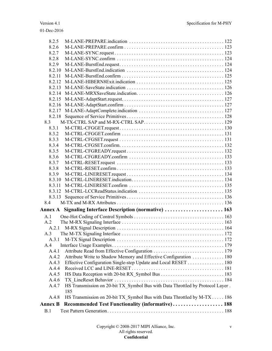
8.2.1 M-LANE-SYMBOL.request
8.2.1.1 Semantics of the Service Primitive
8.2.1.2 When Generated
8.2.1.3 Effect on Receipt
8.2.2 M-LANE-SYMBOL.indication
8.2.2.1 Semantics of the Service Primitive
8.2.2.2 When Generated
8.2.2.3 Effect on Receipt
8.2.3 M-LANE-SYMBOL.confirm
8.2.3.1 Semantics of the Service Primitive
8.2.3.2 When Generated
8.2.3.3 Effect on Receipt
8.2.4 M-LANE-PREPARE.request
8.2.4.1 Semantics of the Service Primitive
8.2.4.2 When Generated
8.2.4.3 Effect on Receipt
8.2.5 M-LANE-PREPARE.indication
8.2.5.1 Semantics of the Service Primitive
8.2.5.2 When Generated
8.2.5.3 Effect on Receipt
8.2.6 M-LANE-PREPARE.confirm
8.2.6.1 Semantics of the Service Primitive
8.2.6.2 When Generated
8.2.6.3 Effect on Receipt
8.2.7 M-LANE-SYNC.request
8.2.7.1 Semantics of the Service Primitive
8.2.7.2 When Generated
8.2.7.3 Effect on Receipt
8.2.8 M-LANE-SYNC.confirm
8.2.8.1 Semantics of the Service Primitive
8.2.8.2 When Generated
8.2.8.3 Effect on Receipt
8.2.9 M-LANE-BurstEnd.request
8.2.9.1 Semantics of the Service Primitive
8.2.9.2 When Generated
8.2.9.3 Effect on Receipt
8.2.10 M-LANE-BurstEnd.indication
8.2.10.1 Semantics of the Service Primitive
8.2.10.2 When Generated
8.2.10.3 Effect on Receipt
8.2.11 M-LANE-BurstEnd.confirm
8.2.11.1 Semantics of the Service Primitive
8.2.11.2 When Generated
8.2.11.3 Effect on Receipt
8.2.12 M-LANE-HIBERN8Exit.indication
8.2.12.1 Semantics of the Service Primitive
8.2.12.2 When Generated
8.2.12.3 Effect on Receipt
8.2.13 M-LANE-SaveState.indication
8.2.13.1 Semantics of the Service Primitive
8.2.13.2 When Generated
8.2.13.3 Effect on Receipt
8.2.14 M-LANE-MRXSaveState.indication
8.2.14.1 Semantics of the Service Primitive
8.2.14.2 When Generated
8.2.14.3 Effect on Receipt
8.2.15 M-LANE-AdaptStart.request
8.2.15.1 Semantics of the Service Primitive
8.2.15.2 When Generated
8.2.15.3 Effect on Receipt
8.2.16 M-LANE-AdaptStart.confirm
8.2.16.1 Semantics of the Service Primitive
8.2.16.2 When Generated
8.2.16.3 Effect on Receipt
8.2.17 M-LANE-AdaptComplete.indication
8.2.17.1 Semantics of the Service Primitive
8.2.17.2 When Generated
8.2.17.3 Effect on Receipt
8.2.18 Sequence of Service Primitives
8.3 M-TX-CTRL SAP and M-RX-CTRL SAP
8.3.1 M-CTRL-CFGGET.request
8.3.1.1 Semantics of the Service Primitive
8.3.1.2 When Generated
8.3.1.3 Effect on Receipt
8.3.2 M-CTRL-CFGGET.confirm
8.3.2.1 Semantics of the Service Primitive
8.3.2.2 When Generated
8.3.2.3 Effect on Receipt
8.3.3 M-CTRL-CFGSET.request
8.3.3.1 Semantics of the Service Primitive
8.3.3.2 When Generated
8.3.3.3 Effect on Receipt
8.3.4 M-CTRL-CFGSET.confirm
8.3.4.1 Semantics of the Service Primitive
8.3.4.2 When Generated
8.3.4.3 Effect on Receipt
8.3.5 M-CTRL-CFGREADY.request
8.3.5.1 Semantics of the Service Primitive
8.3.5.2 When Generated
8.3.5.3 Effect on Receipt
8.3.6 M-CTRL-CFGREADY.confirm
8.3.6.1 Semantics of the Service Primitive
8.3.6.2 When Generated
8.3.6.3 Effect on Receipt
8.3.7 M-CTRL-RESET.request
8.3.7.1 Semantics of the Service Primitive
8.3.7.2 When Generated
8.3.7.3 Effect on Receipt
8.3.8 M-CTRL-RESET.confirm
8.3.8.1 Semantics of the Service Primitive
8.3.8.2 When Generated
8.3.8.3 Effect on Receipt
8.3.9 M-CTRL-LINERESET.request
8.3.9.1 Semantics of the Service Primitive
8.3.9.2 When Generated
8.3.9.3 Effect on Receipt
8.3.10 M-CTRL-LINERESET.indication
8.3.10.1 Semantics of the Service Primitive
8.3.10.2 When Generated
8.3.10.3 Effect on Receipt
8.3.11 M-CTRL-LINERESET.confirm
8.3.11.1 Semantics of the Service Primitive
8.3.11.2 When Generated
8.3.11.3 Effect on Receipt
8.3.12 M-CTRL-LCCReadStatus.indication
8.3.12.1 Semantics of the Service Primitive
8.3.12.2 When Generated
8.3.12.3 Effect on Receipt
8.3.13 Sequence of Service Primitives
8.4 M-TX and M-RX Attributes
Annex A Signaling Interface Description (normative)
A.1 One-Hot Coding of Control Symbols
A.2 The M-RX Signaling Interface
A.2.1 M-RX Signal Description
A.3 The M-TX Signaling Interface
A.3.1 M-TX Signal Description
A.4 Interface Usage Examples
A.4.1 Attribute Read from Effective Configuration
A.4.2 Attribute Write to Shadow Memory and Effective Configuration
A.4.3 Effective Configuration Single-step Update and Local RESET
A.4.4 Received LCC and LINE-RESET
A.4.5 HS Data Reception with 20-bit RX_Symbol Bus
A.4.6 TX_LineReset Behavior
A.4.7 HS Transmission on 20-bit TX_Symbol Bus with Data Throttled by Protocol Layer
A.4.8 HS Transmission on 20-bit TX_Symbol Bus with Data Throttled by M-TX
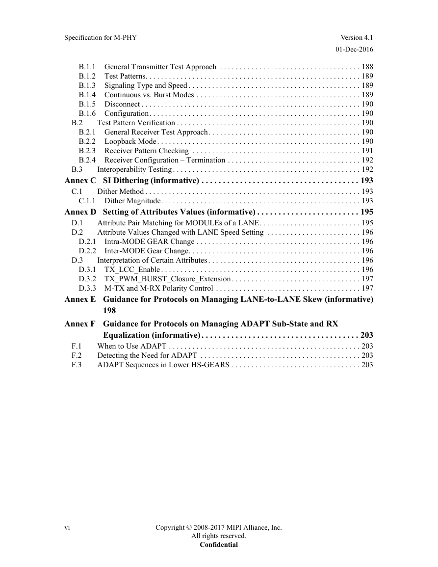
Annex B Recommended Test Functionality (informative)
B.1 Test Pattern Generation
B.1.1 General Transmitter Test Approach
B.1.2 Test Patterns
B.1.3 Signaling Type and Speed
B.1.4 Continuous vs. Burst Modes
B.1.5 Disconnect
B.1.6 Configuration
B.2 Test Pattern Verification
B.2.1 General Receiver Test Approach
B.2.2 Loopback Mode
B.2.2.1 Synchronous vs. Plesiochronous
B.2.3 Receiver Pattern Checking
B.2.4 Receiver Configuration – Termination
B.3 Interoperability Testing
Annex C SI Dithering (informative)
C.1 Dither Method
C.1.1 Dither Magnitude
Annex D Setting of Attributes Values (informative)
D.1 Attribute Pair Matching for MODULEs of a LANE
D.2 Attribute Values Changed with LANE Speed Setting
D.2.1 Intra-MODE GEAR Change
D.2.2 Inter-MODE Gear Change
D.3 Interpretation of Certain Attributes
D.3.1 TX_LCC_Enable
D.3.2 TX_PWM_BURST_Closure_Extension
D.3.3 M-TX and M-RX Polarity Control
Annex E Guidance for Protocols on Managing LANE-to-LANE Skew (informative)
Annex F Guidance for Protocols on Managing ADAPT Sub-State and RX Equalization (informative)
F.1 When to Use ADAPT
F.2 Detecting the Need for ADAPT
F.3 ADAPT Sequences in Lower HS-GEARS




 2023年江西萍乡中考道德与法治真题及答案.doc
 2012年重庆南川中考生物真题及答案.doc
 2013年江西师范大学地理学综合及文艺理论基础考研真题.doc
 2020年四川甘孜小升初语文真题及答案I卷.doc
 2020年注册岩土工程师专业基础考试真题及答案.doc
 2023-2024学年福建省厦门市九年级上学期数学月考试题及答案.doc
 2021-2022学年辽宁省沈阳市大东区九年级上学期语文期末试题及答案.doc
 2022-2023学年北京东城区初三第一学期物理期末试卷及答案.doc
 2018上半年江西教师资格初中地理学科知识与教学能力真题及答案.doc
 2012年河北国家公务员申论考试真题及答案-省级.doc
 2020-2021学年江苏省扬州市江都区邵樊片九年级上学期数学第一次质量检测试题及答案.doc
 2022下半年黑龙江教师资格证中学综合素质真题及答案.doc