logo资料库

TDA7729_07March2013.pdf

第1页 / 共42页
第2页 / 共42页
第3页 / 共42页
第4页 / 共42页
第5页 / 共42页
第6页 / 共42页
第7页 / 共42页
第8页 / 共42页
资料共42页,剩余部分请下载后查看
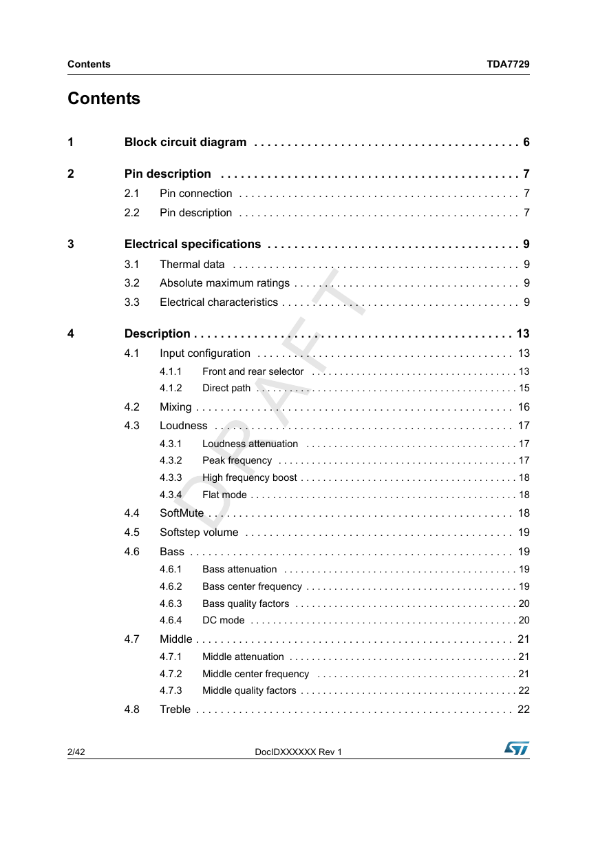
Table 1. Device summary
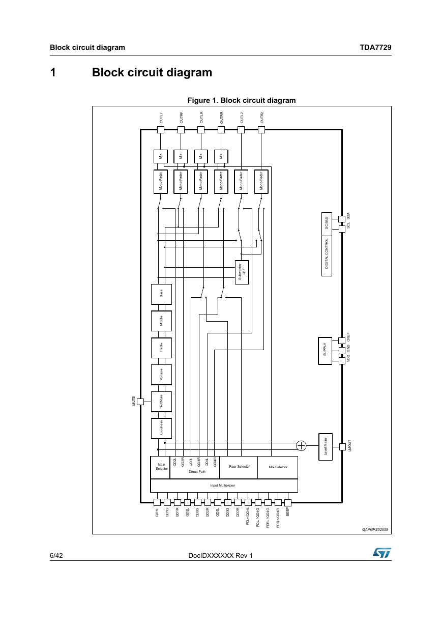
1 Block circuit diagram
Figure 1. Block circuit diagram
2 Pin description
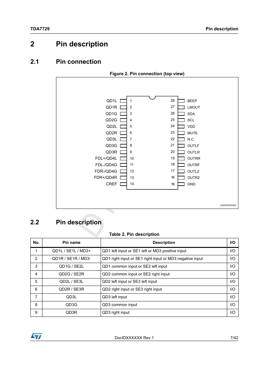
2.1 Pin connection
Figure 2. Pin connection (top view)
2.2 Pin description
Table 2. Pin description
3 Electrical specifications
3.1 Thermal data
Table 3. Thermal data
3.2 Absolute maximum ratings
Table 4. Absolute maximum ratings
3.3 Electrical characteristics
Table 5. Electrical characteristics
4 Description
4.1 Input configuration
4.1.1 Front and rear selector
Table 6. Input pin configuration
Table 7. Selector configuration matrix
Figure 3. QD and FD configuration of QD4/FD4
4.1.2 Direct path
4.2 Mixing
Figure 4. Block diagram of mixing stage
Table 8. Available sources for mixing
4.3 Loudness
4.3.1 Loudness attenuation
Figure 5. Loudness attenuation @ fP = 400 Hz.
4.3.2 Peak frequency
Figure 6. Loudness center frequencies @ Attn. = 15 dB.
4.3.3 High frequency boost
Figure 7. Loudness attenuation, fc =2.4 kHz
4.3.4 Flat mode
4.4 SoftMute
Figure 8. SoftMute timing
4.5 Softstep volume
4.6 Bass
4.6.1 Bass attenuation
Figure 9. Bass Control @ fc = 80 Hz, Q = 1
4.6.2 Bass center frequency
Figure 10. Bass center frequencies @ gain = 14 dB, Q = 1
4.6.3 Bass quality factors
Figure 11. Bass quality factors @ gain = 14 dB, fc = 80 Hz
4.6.4 DC mode
Figure 12. Bass normal and DC mode @ Gain = 14 dB, fc = 80 Hz
4.7 Middle
4.7.1 Middle attenuation
Figure 13. Middle control @ fc = 1 kHz, Q = 1
4.7.2 Middle center frequency
Figure 14. Middle center frequencies @ gain = 14d B, Q = 1
4.7.3 Middle quality factors
Figure 15. Middle quality factors @ gain = 14 dB, fc = 1 kHz
4.8 Treble
4.8.1 Treble attenuation
Figure 16. Treble Control @ fc = 17.5 kHz.
4.8.2 Treble center frequency
Figure 17. Treble center frequencies @ gain = 14 dB
4.9 Subwoofer Filter
Figure 18. Subwoofer control
4.10 Softstep control
4.11 Level meter and beep input
4.12 Output gain control
4.13 Audioprocessor testing
5 I2C bus specification
5.1 Interface protocol
Figure 19. Switching characteristics
Table 9. I2C bus electrical characterisitics
Figure 20. I2C timing diagram
5.1.1 Receive mode
5.1.2 Transmission mode
5.1.3 Reset condition
Table 10. Subaddress (receive mode)
5.2 Data byte specification
Table 11. Input configuration / main selector (0)
Table 12. 2nd Source selector / direct path (1)
Table 13. Mixing source / mixing gain (2)
Table 14. Mix control / level meter (3)
Table 15. Soft mute / others (4)
Table 16. SoftStep I (5)
Table 17. SoftStep II (6)
Table 18. Loudness (7)
Table 19. Volume / output gain (8)
Table 20. Treble filter (9)
Table 21. Middle filter (10)
Table 22. Bass filter (11)
Table 23. Subwoofer / middle / bass (12)
Table 24. Speaker attenuation (LF/RF/LR/RR) (13-16)
Table 25. Subwoofer attenuation (subwoofer L/subwoofer R) (17-18)
6 Package information
Figure 21. TSSOP28 mechanical data and package dimensions
7 Revision history
Table 26. Document revision history
TDA7729 3 band car audio processor Datasheet - production data – Center frequency programmable in 4 steps – -15 to 15dB range with 1dB resolution  Speaker – 4 independent soft step speaker controls – 0dB to -79dB with 1dB steps – Direct mute  Subwoofer – 2nd order low pass filter with programmable cut off frequency – 2 independent soft step level control,  Mute functions – Direct mute – Digitally controlled SoftMute with 4 programmable mute-times  Level meter – Provide rectified level voltage of main source signal (before loudness)  Rear seat selector – Full source selector for rear seat output  Mixing selector Description The TDA7729 is a high performance signal processor specifically designed for car radio applications. The device includes a high performance audioprocessor with fully integrated audio filters and new Soft Step architecture. The digital control allows programming in a wide range of filter characteristics. By the use of BCMOS- process and liner signal processing low distortion and low noise are obtained. Table 1. Device summary Order code TDA7729 TDA7729TR Package TSSOP28 TSSOP28 Packing Tube Tape and reel TSSOP28 Features  Input multiplexer – Multiple input configuration for different application  Loudness – 2nd order frequency response – Programmable center frequency – 15 dB with 1 dB steps – Selectable high frequency boost – Selectable flat-mode  Volume – +15 dB to -15 dB with 1 dB step resolution – Soft-step control with programmable blend times  Bass – 2nd order frequency response – Center frequency programmable in 4 steps – Q programmable 1.0/1.25/1.5/2.0 – DC gain programmable – -15 to 15 dB range with 1 dB resolution  Middle – 2nd order frequency response – Center frequency programmable in 4 steps – Q programmable 0.5/0.75/1.0/1.25 – -15 to 15dB range with 1dB resolution  Treble – 2nd order frequency response 7 March 2013 This is information on a product in full production. DocIDXXXXXX Rev 1 1/42 www.st.com 1
Contents Contents TDA7729 1 2 3 4 Block circuit diagram . . . . . . . . . . . . . . . . . . . . . . . . . . . . . . . . . . . . . . . . 6 Pin description . . . . . . . . . . . . . . . . . . . . . . . . . . . . . . . . . . . . . . . . . . . . . 7 Pin connection . . . . . . . . . . . . . . . . . . . . . . . . . . . . . . . . . . . . . . . . . . . . . . 7 2.1 2.2 Pin description . . . . . . . . . . . . . . . . . . . . . . . . . . . . . . . . . . . . . . . . . . . . . . 7 Electrical specifications . . . . . . . . . . . . . . . . . . . . . . . . . . . . . . . . . . . . . . 9 Thermal data . . . . . . . . . . . . . . . . . . . . . . . . . . . . . . . . . . . . . . . . . . . . . . . 9 3.1 3.2 Absolute maximum ratings . . . . . . . . . . . . . . . . . . . . . . . . . . . . . . . . . . . . . 9 Electrical characteristics . . . . . . . . . . . . . . . . . . . . . . . . . . . . . . . . . . . . . . . 9 3.3 4.2 4.3 Description . . . . . . . . . . . . . . . . . . . . . . . . . . . . . . . . . . . . . . . . . . . . . . . . 13 Input configuration . . . . . . . . . . . . . . . . . . . . . . . . . . . . . . . . . . . . . . . . . . 13 4.1 4.1.1 Front and rear selector . . . . . . . . . . . . . . . . . . . . . . . . . . . . . . . . . . . . . 13 4.1.2 Direct path . . . . . . . . . . . . . . . . . . . . . . . . . . . . . . . . . . . . . . . . . . . . . . . 15 Mixing . . . . . . . . . . . . . . . . . . . . . . . . . . . . . . . . . . . . . . . . . . . . . . . . . . . . 16 Loudness . . . . . . . . . . . . . . . . . . . . . . . . . . . . . . . . . . . . . . . . . . . . . . . . . 17 Loudness attenuation . . . . . . . . . . . . . . . . . . . . . . . . . . . . . . . . . . . . . . 17 4.3.1 Peak frequency . . . . . . . . . . . . . . . . . . . . . . . . . . . . . . . . . . . . . . . . . . . 17 4.3.2 4.3.3 High frequency boost . . . . . . . . . . . . . . . . . . . . . . . . . . . . . . . . . . . . . . . 18 4.3.4 Flat mode . . . . . . . . . . . . . . . . . . . . . . . . . . . . . . . . . . . . . . . . . . . . . . . . 18 SoftMute . . . . . . . . . . . . . . . . . . . . . . . . . . . . . . . . . . . . . . . . . . . . . . . . . . 18 Softstep volume . . . . . . . . . . . . . . . . . . . . . . . . . . . . . . . . . . . . . . . . . . . . 19 Bass . . . . . . . . . . . . . . . . . . . . . . . . . . . . . . . . . . . . . . . . . . . . . . . . . . . . . 19 Bass attenuation . . . . . . . . . . . . . . . . . . . . . . . . . . . . . . . . . . . . . . . . . . 19 4.6.1 4.6.2 Bass center frequency . . . . . . . . . . . . . . . . . . . . . . . . . . . . . . . . . . . . . . 19 Bass quality factors . . . . . . . . . . . . . . . . . . . . . . . . . . . . . . . . . . . . . . . . 20 4.6.3 4.6.4 DC mode . . . . . . . . . . . . . . . . . . . . . . . . . . . . . . . . . . . . . . . . . . . . . . . . 20 Middle . . . . . . . . . . . . . . . . . . . . . . . . . . . . . . . . . . . . . . . . . . . . . . . . . . . . 21 Middle attenuation . . . . . . . . . . . . . . . . . . . . . . . . . . . . . . . . . . . . . . . . . 21 4.7.1 4.7.2 Middle center frequency . . . . . . . . . . . . . . . . . . . . . . . . . . . . . . . . . . . . 21 4.7.3 Middle quality factors . . . . . . . . . . . . . . . . . . . . . . . . . . . . . . . . . . . . . . . 22 Treble . . . . . . . . . . . . . . . . . . . . . . . . . . . . . . . . . . . . . . . . . . . . . . . . . . . . 22 4.4 4.5 4.6 4.7 4.8 2/42 DocIDXXXXXX Rev 1
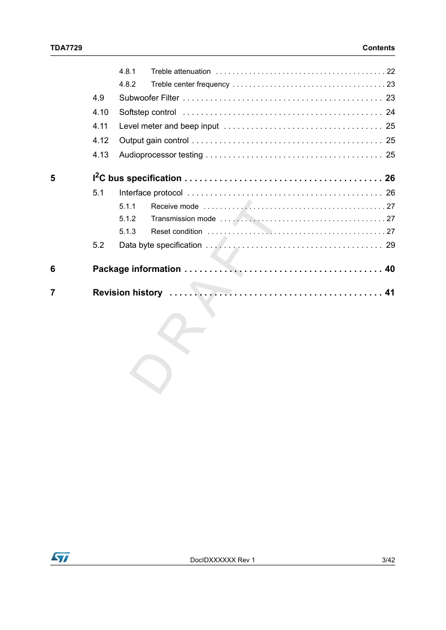
TDA7729 Contents Treble attenuation . . . . . . . . . . . . . . . . . . . . . . . . . . . . . . . . . . . . . . . . . 22 4.8.1 4.8.2 Treble center frequency . . . . . . . . . . . . . . . . . . . . . . . . . . . . . . . . . . . . . 23 4.9 Subwoofer Filter . . . . . . . . . . . . . . . . . . . . . . . . . . . . . . . . . . . . . . . . . . . . 23 4.10 Softstep control . . . . . . . . . . . . . . . . . . . . . . . . . . . . . . . . . . . . . . . . . . . . 24 4.11 Level meter and beep input . . . . . . . . . . . . . . . . . . . . . . . . . . . . . . . . . . . 25 4.12 Output gain control . . . . . . . . . . . . . . . . . . . . . . . . . . . . . . . . . . . . . . . . . . 25 4.13 Audioprocessor testing . . . . . . . . . . . . . . . . . . . . . . . . . . . . . . . . . . . . . . . 25 I2C bus specification . . . . . . . . . . . . . . . . . . . . . . . . . . . . . . . . . . . . . . . . 26 Interface protocol . . . . . . . . . . . . . . . . . . . . . . . . . . . . . . . . . . . . . . . . . . . 26 5.1 5.1.1 Receive mode . . . . . . . . . . . . . . . . . . . . . . . . . . . . . . . . . . . . . . . . . . . . 27 Transmission mode . . . . . . . . . . . . . . . . . . . . . . . . . . . . . . . . . . . . . . . . 27 5.1.2 5.1.3 Reset condition . . . . . . . . . . . . . . . . . . . . . . . . . . . . . . . . . . . . . . . . . . . 27 Data byte specification . . . . . . . . . . . . . . . . . . . . . . . . . . . . . . . . . . . . . . . 29 5.2 Package information . . . . . . . . . . . . . . . . . . . . . . . . . . . . . . . . . . . . . . . . 40 Revision history . . . . . . . . . . . . . . . . . . . . . . . . . . . . . . . . . . . . . . . . . . . 41 5 6 7 DocIDXXXXXX Rev 1 3/42
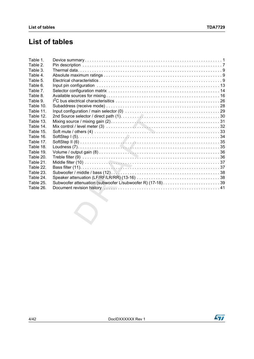
List of tables List of tables TDA7729 Device summary . . . . . . . . . . . . . . . . . . . . . . . . . . . . . . . . . . . . . . . . . . . . . . . . . . . . . . . . . . 1 Table 1. Pin description . . . . . . . . . . . . . . . . . . . . . . . . . . . . . . . . . . . . . . . . . . . . . . . . . . . . . . . . . . . 7 Table 2. Thermal data. . . . . . . . . . . . . . . . . . . . . . . . . . . . . . . . . . . . . . . . . . . . . . . . . . . . . . . . . . . . . 9 Table 3. Absolute maximum ratings . . . . . . . . . . . . . . . . . . . . . . . . . . . . . . . . . . . . . . . . . . . . . . . . . . 9 Table 4. Electrical characteristics . . . . . . . . . . . . . . . . . . . . . . . . . . . . . . . . . . . . . . . . . . . . . . . . . . . . 9 Table 5. Input pin configuration . . . . . . . . . . . . . . . . . . . . . . . . . . . . . . . . . . . . . . . . . . . . . . . . . . . . 13 Table 6. Selector configuration matrix . . . . . . . . . . . . . . . . . . . . . . . . . . . . . . . . . . . . . . . . . . . . . . . 14 Table 7. Available sources for mixing . . . . . . . . . . . . . . . . . . . . . . . . . . . . . . . . . . . . . . . . . . . . . . . . 16 Table 8. I2C bus electrical characterisitics . . . . . . . . . . . . . . . . . . . . . . . . . . . . . . . . . . . . . . . . . . . . 26 Table 9. Subaddress (receive mode) . . . . . . . . . . . . . . . . . . . . . . . . . . . . . . . . . . . . . . . . . . . . . . . . 28 Table 10. Input configuration / main selector (0) . . . . . . . . . . . . . . . . . . . . . . . . . . . . . . . . . . . . . . . . 29 Table 11. Table 12. 2nd Source selector / direct path (1). . . . . . . . . . . . . . . . . . . . . . . . . . . . . . . . . . . . . . . . . . 30 Table 13. Mixing source / mixing gain (2) . . . . . . . . . . . . . . . . . . . . . . . . . . . . . . . . . . . . . . . . . . . . . . 31 Table 14. Mix control / level meter (3) . . . . . . . . . . . . . . . . . . . . . . . . . . . . . . . . . . . . . . . . . . . . . . . . 32 Soft mute / others (4) . . . . . . . . . . . . . . . . . . . . . . . . . . . . . . . . . . . . . . . . . . . . . . . . . . . . . 33 Table 15. SoftStep I (5). . . . . . . . . . . . . . . . . . . . . . . . . . . . . . . . . . . . . . . . . . . . . . . . . . . . . . . . . . . . 34 Table 16. Table 17. SoftStep II (6) . . . . . . . . . . . . . . . . . . . . . . . . . . . . . . . . . . . . . . . . . . . . . . . . . . . . . . . . . . . 35 Loudness (7). . . . . . . . . . . . . . . . . . . . . . . . . . . . . . . . . . . . . . . . . . . . . . . . . . . . . . . . . . . . 35 Table 18. Volume / output gain (8) . . . . . . . . . . . . . . . . . . . . . . . . . . . . . . . . . . . . . . . . . . . . . . . . . . . 36 Table 19. Table 20. Treble filter (9) . . . . . . . . . . . . . . . . . . . . . . . . . . . . . . . . . . . . . . . . . . . . . . . . . . . . . . . . . . 36 Table 21. Middle filter (10) . . . . . . . . . . . . . . . . . . . . . . . . . . . . . . . . . . . . . . . . . . . . . . . . . . . . . . . . . 37 Bass filter (11). . . . . . . . . . . . . . . . . . . . . . . . . . . . . . . . . . . . . . . . . . . . . . . . . . . . . . . . . . . 37 Table 22. Subwoofer / middle / bass (12) . . . . . . . . . . . . . . . . . . . . . . . . . . . . . . . . . . . . . . . . . . . . . . 38 Table 23. Speaker attenuation (LF/RF/LR/RR) (13-16) . . . . . . . . . . . . . . . . . . . . . . . . . . . . . . . . . . . 38 Table 24. Table 25. Subwoofer attenuation (subwoofer L/subwoofer R) (17-18) . . . . . . . . . . . . . . . . . . . . . . . . 39 Document revision history . . . . . . . . . . . . . . . . . . . . . . . . . . . . . . . . . . . . . . . . . . . . . . . . . 41 Table 26. 4/42 DocIDXXXXXX Rev 1
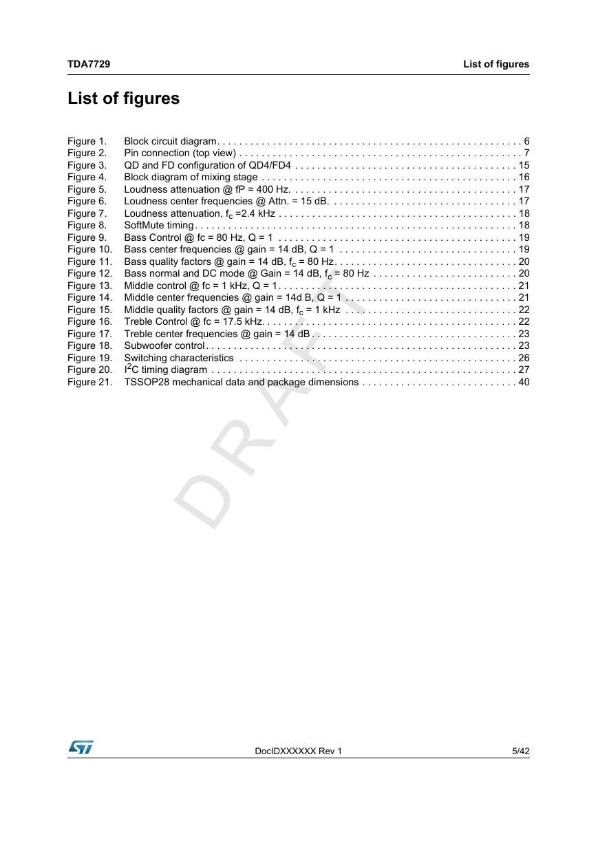
TDA7729 List of figures List of figures Block circuit diagram. . . . . . . . . . . . . . . . . . . . . . . . . . . . . . . . . . . . . . . . . . . . . . . . . . . . . . . 6 Figure 1. Pin connection (top view) . . . . . . . . . . . . . . . . . . . . . . . . . . . . . . . . . . . . . . . . . . . . . . . . . . . 7 Figure 2. QD and FD configuration of QD4/FD4 . . . . . . . . . . . . . . . . . . . . . . . . . . . . . . . . . . . . . . . . 15 Figure 3. Block diagram of mixing stage . . . . . . . . . . . . . . . . . . . . . . . . . . . . . . . . . . . . . . . . . . . . . . 16 Figure 4. Loudness attenuation @ fP = 400 Hz. . . . . . . . . . . . . . . . . . . . . . . . . . . . . . . . . . . . . . . . . 17 Figure 5. Loudness center frequencies @ Attn. = 15 dB. . . . . . . . . . . . . . . . . . . . . . . . . . . . . . . . . . 17 Figure 6. Loudness attenuation, fc =2.4 kHz . . . . . . . . . . . . . . . . . . . . . . . . . . . . . . . . . . . . . . . . . . . 18 Figure 7. SoftMute timing. . . . . . . . . . . . . . . . . . . . . . . . . . . . . . . . . . . . . . . . . . . . . . . . . . . . . . . . . . 18 Figure 8. Figure 9. Bass Control @ fc = 80 Hz, Q = 1 . . . . . . . . . . . . . . . . . . . . . . . . . . . . . . . . . . . . . . . . . . . 19 Figure 10. Bass center frequencies @ gain = 14 dB, Q = 1 . . . . . . . . . . . . . . . . . . . . . . . . . . . . . . . . 19 Figure 11. Bass quality factors @ gain = 14 dB, fc = 80 Hz. . . . . . . . . . . . . . . . . . . . . . . . . . . . . . . . . 20 Figure 12. Bass normal and DC mode @ Gain = 14 dB, fc = 80 Hz . . . . . . . . . . . . . . . . . . . . . . . . . . 20 Figure 13. Middle control @ fc = 1 kHz, Q = 1. . . . . . . . . . . . . . . . . . . . . . . . . . . . . . . . . . . . . . . . . . . 21 Figure 14. Middle center frequencies @ gain = 14d B, Q = 1 . . . . . . . . . . . . . . . . . . . . . . . . . . . . . . . 21 Figure 15. Middle quality factors @ gain = 14 dB, fc = 1 kHz . . . . . . . . . . . . . . . . . . . . . . . . . . . . . . . 22 Figure 16. Treble Control @ fc = 17.5 kHz. . . . . . . . . . . . . . . . . . . . . . . . . . . . . . . . . . . . . . . . . . . . . . 22 Figure 17. Treble center frequencies @ gain = 14 dB . . . . . . . . . . . . . . . . . . . . . . . . . . . . . . . . . . . . . 23 Figure 18. Subwoofer control. . . . . . . . . . . . . . . . . . . . . . . . . . . . . . . . . . . . . . . . . . . . . . . . . . . . . . . . 23 Figure 19. Switching characteristics . . . . . . . . . . . . . . . . . . . . . . . . . . . . . . . . . . . . . . . . . . . . . . . . . . 26 I2C timing diagram . . . . . . . . . . . . . . . . . . . . . . . . . . . . . . . . . . . . . . . . . . . . . . . . . . . . . . . 27 Figure 20. Figure 21. TSSOP28 mechanical data and package dimensions . . . . . . . . . . . . . . . . . . . . . . . . . . . . 40 DocIDXXXXXX Rev 1 5/42
Block circuit diagram TDA7729 1 Block circuit diagram Figure 1. Block circuit diagram 6/42 DocIDXXXXXX Rev 1
TDA7729 2 Pin description 2.1 Pin connection Pin description Figure 2. Pin connection (top view) 2.2 No. 1 2 3 4 5 6 7 8 9 Pin description Pin name QD1L / SE1L / MD3+ QD1R / SE1R / MD3- QD1G / SE2L QD2G / SE2R QD2L / SE3L QD2R / SE3R QD3L QD3G QD3R Table 2. Pin description Description QD1 left input or SE1 left or MD3 positive input QD1 right input or SE1 right input or MD3 negative input QD1 common input or SE2 left input QD2 common input or SE2 right input QD2 left input or SE3 left input QD2 right input or SE3 right input QD3 left input QD3 common input QD3 right input DocIDXXXXXX Rev 1 I/O I/O I/O I/O I/O I/O I/O I/O I/O I/O 7/42
Pin description TDA7729 Table 2. Pin description (continued) Description Pin name No. 10 QD4L / FD4L+ / SE4L / MD1+ QD4 left input or FD4L positive input or SE4 left input or MD1 positive input 11 QD4G / FD4L- / SE4R / MD1- QD4 common input or FD4L negative input or SE4 right input or MD1 negative input 12 QD4G / FD4R- / SE5L / MD2- QD4 common input or FD4R negative input or SE5 left input or MD2 negative input 13 QD4R / FD4R+ / SE5R / MD2+ QD4 right input or FD4R positive input or SE5 right input or MD2 14 15 16 17 18 19 20 21 22 23 24 25 26 27 28 CREF GND OUTR2 OUTL2 OUTRF OUTRR OUTLR OUTLF N.C. MUTE VDD SCL SDA LMOUT Beep positive input Reference capacitor Ground Subwoofer output / 2nd right output Subwoofer output / 2nd left output Front right output Rear right output Rear left output Front left output Floating I2C bus data Supply I2C bus clock I2C bus data Level meter output Beep input (Mono Single-Ended input) I/O I/O I/O I/O I/O O S O O O O O O N.C. I/O S I I/O O I 8/42 DocIDXXXXXX Rev 1
分享到:
收藏