ANSI/VITA 46.0-2007
American National Standard
for VPX Baseline Standard
Secretariat
VMEbus International Trade Association
Approved October 2007
American National Standards Institute, Inc.
VMEbus International Trade Association
PO Box 19658, Fountain Hills, AZ 85269
PH: 480-837-7486, FAX: Contact VITA Office
E-mail: info@vita.com, URL: http://www.vita.com
�
ANSI/VITA 46.0, VPX
Revision History
Date
Oct 2007
Feb 2008
Revision
R1.0
R1.1
April 2008
R1.2
Comment
Initial Release
Errors in the following figures were corrected.
Appendix B – figures: B-1, B-2, B-3, B-4
Page 25, Recommendation 3-6, Change text from “ANSI-
VITA 40-2004” to “ANSI/VITA 40, Status Indicator
Standard”
�
ANSI/VITA 46.0-2007
American National Standard
for VPX Baseline Standard
Secretariat
VMEbus International Trade Association
Approved October 2007
American National Standards Institute, Inc.
Abstract
This standard describes VITA 46.0 VPX Baseline Standard, an evolutionary
step forward for the provision of high-speed interconnects in harsh
environment applications.
�
American
National
Standard
Approval of an American National Standard requires verification
by ANSI that the requirements for due process, consensus, and
other criteria for approval have been met by the standards
developer.
Consensus is established when, in the judgment of the ANSI
Board of Standards Review, substantial agreement has been
reached by directly and materially affected interests.
Substantial agreement means much more than a simple
majority, but not necessarily unanimity. Consensus requires
that all views and objections be considered, and that a concerted
effort be made toward their resolution.
The use of American National Standards is completely voluntary;
their existence does not in any respect preclude anyone, whether
he has approved the standards or not, from manufacturing,
marketing, purchasing, or using products, processes, or
procedures not conforming to the standards.
The American National Standards Institute does not develop
standards and will in no circumstances give an interpretation of
any American National Standard. Moreover, no person shall
have the right or authority to issue an interpretation of an
American National Standard in the name of the American
National Standard Institute. Requests for interpretations should
be addressed to the secretariat or sponsor whose name appears
on the title page of this standard.
CAUTION NOTICE: This American National Standard may be
revised or withdrawn at any time. The procedures of the
American National Standards Institute require that action be
taken periodically to reaffirm, revise, or withdraw this standard.
Purchases of American National Standards may receive current
information on all standard by calling or writing the American
National Standards Institute.
NOTE – The user’s attention is called to the possibility that compliance with this standard
may require use of an invention covered by patent rights.
By publication of this standard, no position is taken with respect to the validity of this
claim or of any patent rights in connection therewith. The patent holder has, however,
filed a statement of willingness to grant a license under these rights on reasonable and
nondiscriminatory terms and conditions to applicants desiring to obtain such a license.
Details may be obtained from the standards developer.
Published by
VMEbus International Trade Association
PO Box 19658, Fountain Hills, AZ 85269
Copyright © 2007 by VMEbus International Trade Association
All rights reserved.
No part of this publication may be reproduced in any form, in an electronic retrieval
system or otherwise, without prior written permission of the publisher.
Printed in the United States of America - R1.2, ISBN 1-885731-44-2
�
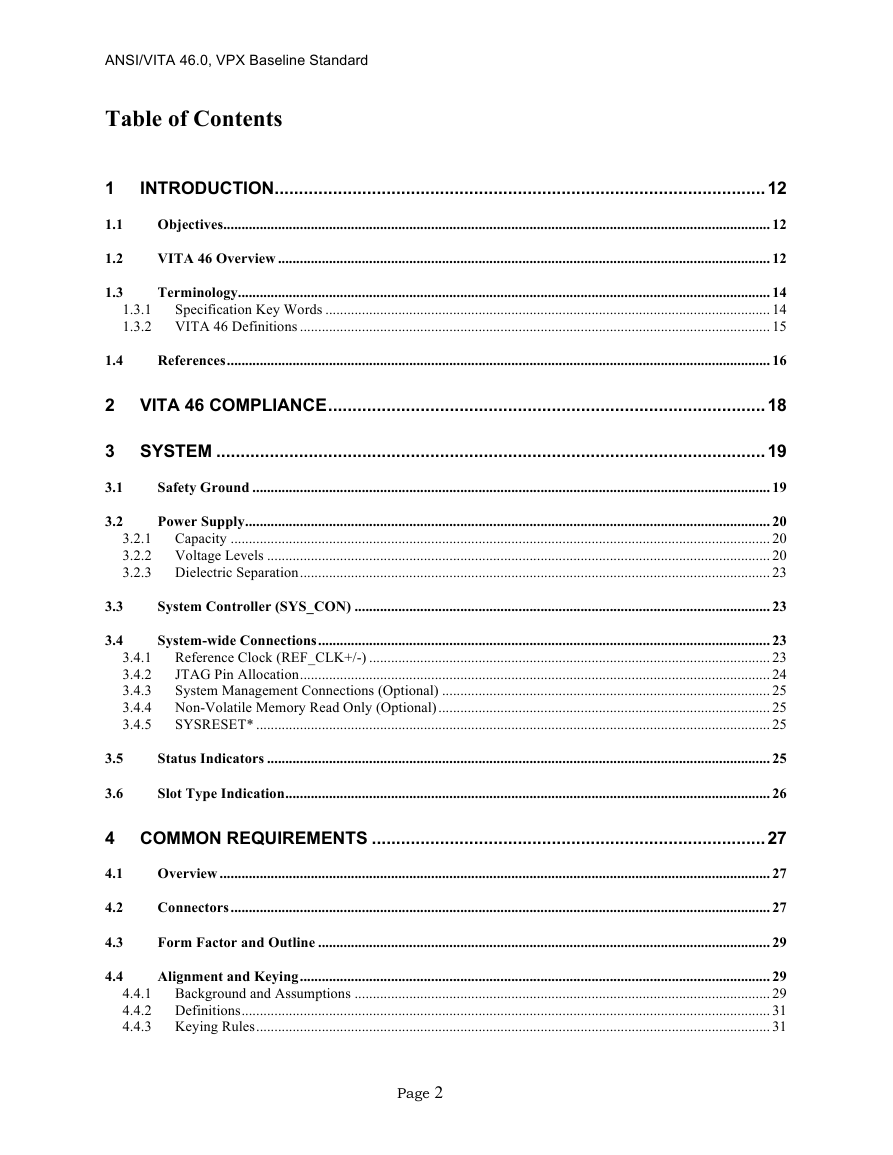
ANSI/VITA 46.0, VPX Baseline Standard
Table of Contents
1
1.1
1.2
1.3
INTRODUCTION.....................................................................................................12
Objectives...................................................................................................................................................... 12
VITA 46 Overview ....................................................................................................................................... 12
Terminology.................................................................................................................................................. 14
1.3.1
Specification Key Words .......................................................................................................................... 14
1.3.2 VITA 46 Definitions ................................................................................................................................. 15
References..................................................................................................................................................... 16
1.4
2 VITA 46 COMPLIANCE..........................................................................................18
3 SYSTEM .................................................................................................................19
Safety Ground .............................................................................................................................................. 19
3.1
Power Supply................................................................................................................................................ 20
3.2
3.2.1 Capacity .................................................................................................................................................... 20
3.2.2 Voltage Levels .......................................................................................................................................... 20
3.2.3 Dielectric Separation................................................................................................................................. 23
System Controller (SYS_CON) .................................................................................................................. 23
System-wide Connections............................................................................................................................ 23
3.4.1 Reference Clock (REF_CLK+/-) .............................................................................................................. 23
JTAG Pin Allocation................................................................................................................................. 24
3.4.2
3.4.3
System Management Connections (Optional) .......................................................................................... 25
3.4.4 Non-Volatile Memory Read Only (Optional)........................................................................................... 25
SYSRESET* ............................................................................................................................................. 25
3.4.5
Status Indicators .......................................................................................................................................... 25
Slot Type Indication..................................................................................................................................... 26
3.5
3.6
3.3
3.4
4 COMMON REQUIREMENTS .................................................................................27
Overview ....................................................................................................................................................... 27
4.1
4.2
Connectors.................................................................................................................................................... 27
Form Factor and Outline ............................................................................................................................ 29
4.3
4.4
Alignment and Keying................................................................................................................................. 29
4.4.1 Background and Assumptions .................................................................................................................. 29
4.4.2 Definitions................................................................................................................................................. 31
4.4.3 Keying Rules............................................................................................................................................. 31
Page 2
�
ANSI/VITA 46.0, VPX Baseline Standard
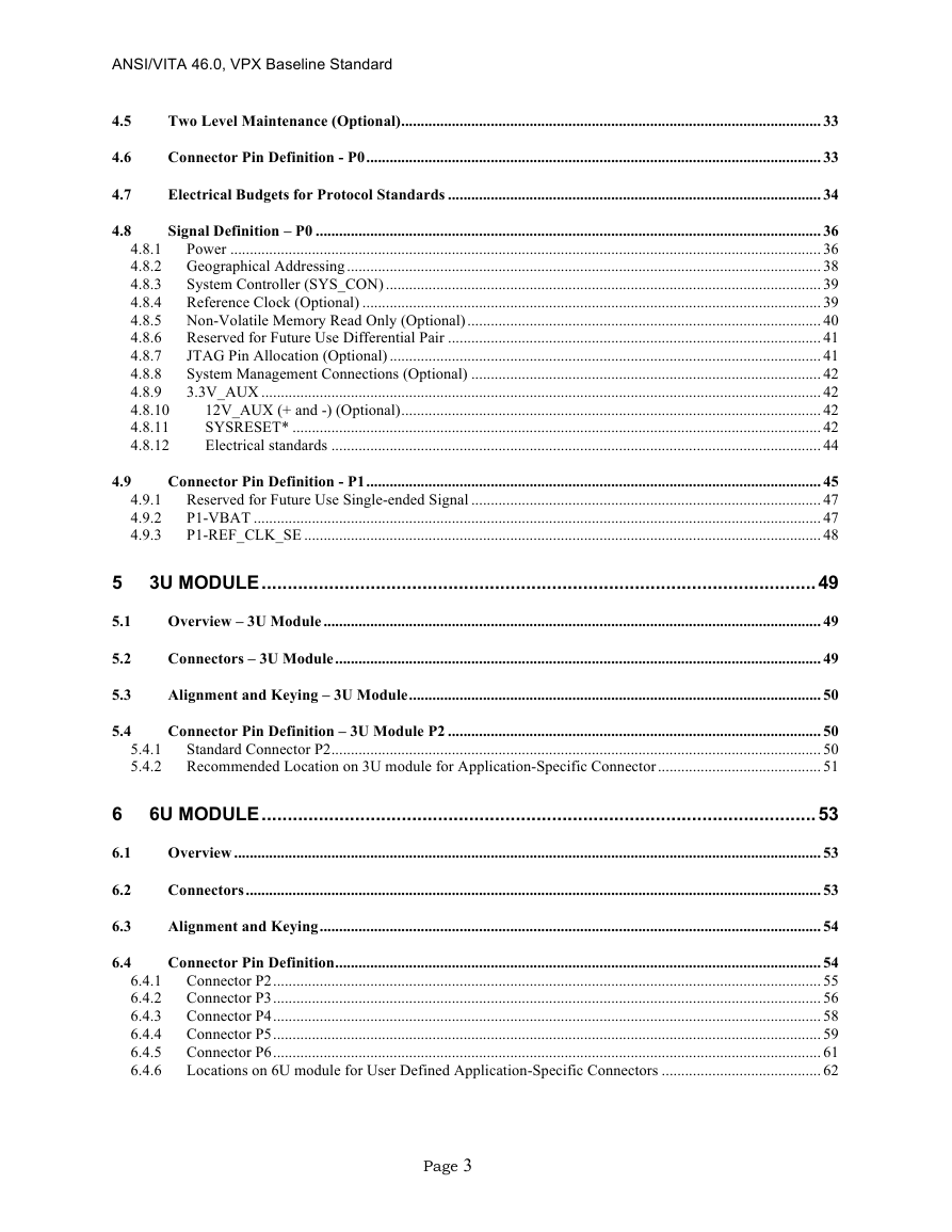
4.5
4.6
4.7
4.8
Two Level Maintenance (Optional)............................................................................................................ 33
Connector Pin Definition - P0..................................................................................................................... 33
Electrical Budgets for Protocol Standards ................................................................................................ 34
Signal Definition – P0 .................................................................................................................................. 36
4.8.1
Power ........................................................................................................................................................ 36
4.8.2 Geographical Addressing.......................................................................................................................... 38
4.8.3
System Controller (SYS_CON) ................................................................................................................ 39
4.8.4 Reference Clock (Optional) ...................................................................................................................... 39
4.8.5 Non-Volatile Memory Read Only (Optional)........................................................................................... 40
4.8.6 Reserved for Future Use Differential Pair ................................................................................................ 41
4.8.7
JTAG Pin Allocation (Optional) ............................................................................................................... 41
System Management Connections (Optional) .......................................................................................... 42
4.8.8
3.3V_AUX ................................................................................................................................................ 42
4.8.9
4.8.10
12V_AUX (+ and -) (Optional)............................................................................................................ 42
4.8.11
SYSRESET* ........................................................................................................................................ 42
Electrical standards .............................................................................................................................. 44
4.8.12
Connector Pin Definition - P1..................................................................................................................... 45
4.9.1 Reserved for Future Use Single-ended Signal .......................................................................................... 47
P1-VBAT .................................................................................................................................................. 47
4.9.2
P1-REF_CLK_SE ..................................................................................................................................... 48
4.9.3
4.9
5
5.1
5.2
5.3
5.4
3U MODULE...........................................................................................................49
Overview – 3U Module ................................................................................................................................ 49
Connectors – 3U Module............................................................................................................................. 49
Alignment and Keying – 3U Module.......................................................................................................... 50
Connector Pin Definition – 3U Module P2 ................................................................................................ 50
Standard Connector P2.............................................................................................................................. 50
5.4.1
5.4.2 Recommended Location on 3U module for Application-Specific Connector.......................................... 51
6
6.1
6.2
6.3
6.4
6U MODULE...........................................................................................................53
Overview ....................................................................................................................................................... 53
Connectors.................................................................................................................................................... 53
Alignment and Keying................................................................................................................................. 54
Connector Pin Definition............................................................................................................................. 54
6.4.1 Connector P2............................................................................................................................................. 55
6.4.2 Connector P3............................................................................................................................................. 56
6.4.3 Connector P4............................................................................................................................................. 58
6.4.4 Connector P5............................................................................................................................................. 59
6.4.5 Connector P6............................................................................................................................................. 61
Locations on 6U module for User Defined Application-Specific Connectors ......................................... 62
6.4.6
Page 3
�
ANSI/VITA 46.0, VPX Baseline Standard
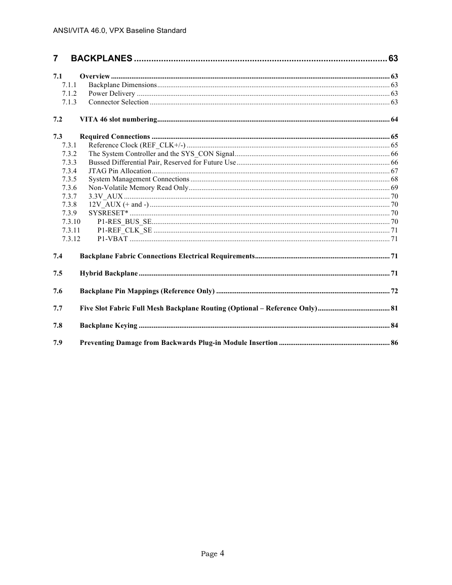
7.2
7.3
7 BACKPLANES .......................................................................................................63
Overview ....................................................................................................................................................... 63
7.1
7.1.1 Backplane Dimensions.............................................................................................................................. 63
Power Delivery ......................................................................................................................................... 63
7.1.2
7.1.3 Connector Selection .................................................................................................................................. 63
VITA 46 slot numbering.............................................................................................................................. 64
Required Connections ................................................................................................................................. 65
7.3.1 Reference Clock (REF_CLK+/-) .............................................................................................................. 65
The System Controller and the SYS_CON Signal.................................................................................... 66
7.3.2
7.3.3 Bussed Differential Pair, Reserved for Future Use................................................................................... 66
7.3.4
JTAG Pin Allocation................................................................................................................................. 67
System Management Connections ............................................................................................................ 68
7.3.5
7.3.6 Non-Volatile Memory Read Only............................................................................................................. 69
7.3.7
3.3V_AUX ................................................................................................................................................ 70
7.3.8
12V_AUX (+ and -) .................................................................................................................................. 70
SYSRESET* ............................................................................................................................................. 70
7.3.9
P1-RES_BUS_SE................................................................................................................................. 70
7.3.10
7.3.11
P1-REF_CLK_SE ................................................................................................................................ 71
7.3.12
P1-VBAT ............................................................................................................................................. 71
Backplane Fabric Connections Electrical Requirements......................................................................... 71
Hybrid Backplane ........................................................................................................................................ 71
Backplane Pin Mappings (Reference Only) .............................................................................................. 72
Five Slot Fabric Full Mesh Backplane Routing (Optional – Reference Only)....................................... 81
Backplane Keying ........................................................................................................................................ 84
Preventing Damage from Backwards Plug-in Module Insertion ............................................................ 86
7.4
7.5
7.6
7.7
7.8
7.9
Page 4
�
ANSI/VITA 46.0, VPX Baseline Standard
List of Figures
FIGURE 4-1 CONNECTOR IDENTIFICATION FOR 3U AND 6U MODULES..................................... 28
FIGURE 4-2 VITA 46 KEYING SYSTEM ......................................................................................... 30
FIGURE 7-1: RES_BUS+/- GACKPLANE TERMINATION............................................................. 67
FIGURE 7-3: SINGLE-ENDED PLUG-IN MODULE WAFER TO BACKPLANE PIN MAPPINGS............... 73
FIGURE 7-4: ODD DIFFERENTIAL PLUG-IN MODULE WAFER TO BACKPLANE PIN MAPPINGS........ 74
FIGURE 7-5: EVEN DIFFERENTIAL PLUG-IN MODULE WAFER TO BACKPLANE PIN MAPPINGS ...... 74
FIGURE 7-6: POWER WAFER TO BACKPLANE PIN MAPPINGS......................................................... 75
FIGURE 7-7 RECOMMENDED PORT CONNECTION SCHEME............................................................. 83
FIGURE A-1 3U AIR COOLED MODULE LAYOUT ........................................................................... 88
FIGURE A-2 3U CONDUCTION COOLED LAYOUT........................................................................... 89
FIGURE A-3 6U AIR COOLED LAYOUT .......................................................................................... 90
FIGURE A-4 6U CONDUCTION COOLED LAYOUT........................................................................... 91
FIGURE A-5 3U CONDUCTION COOLED MODULE END VIEW ........................................................ 92
FIGURE A-6 6U CONDUCTION COOLED MODULE END VIEW ........................................................ 93
FIGURE A-7 3U CHASSIS SIDE WALL ............................................................................................ 94
FIGURE A-8 CONDUCTION COOLED MODULE SIDE VIEW.............................................................. 95
FIGURE B-1 3U AIR COOLED BACKPLANE, PLAN VIEW................................................................ 96
FIGURE B-2 6U AIR COOLED BACKPLANE, PLAN VIEW................................................................ 97
FIGURE B-3 3U CONDUCTION COOLED BACKPLANE, PLAN VIEW................................................. 98
FIGURE B-4 6U CONDUCTION COOLED BACKPLANE, PLAN VIEW................................................. 99
FIGURE B-5 6U BACKPLANE, END VIEW..................................................................................... 100
FIGURE C-1 3U PCB FABRICATION DRAWING (VIEWED FROM PRIMARY SIDE) .......................... 101
FIGURE C-2 6U PCB FABRICATION DRAWING (VIEWED FROM PRIMARY SIDE) .......................... 102
FIGURE D-1: TOP VIEW OF AIR COOLED CHASSIS SHOWING CORRECT PLUG-IN MODULE INSERTION
(TOP MODULE) AND BACKWARDS PLUG-IN MODULE INSERTION (BOTTOM MODULE)............ 103
FIGURE D-2: CONCEPT FOR “STOPPER COMB” FASTENED TO CHASSIS, FOR PREVENTING CONNECTOR
DAMAGE FROM BACKWARDS AIR COOLED PLUG-IN MODULE INSERTION .............................. 104
FIGURE D-3: CONCEPT FOR HEX STAND-OFF FASTENED TO BACKPLANE, FOR PREVENTING
CONNECTOR DAMAGE FROM BACKWARDS AIR COOLED PLUG-IN MODULE INSERTION .......... 104
Page 5
�



 2023年江西萍乡中考道德与法治真题及答案.doc
 2012年重庆南川中考生物真题及答案.doc
 2013年江西师范大学地理学综合及文艺理论基础考研真题.doc
 2020年四川甘孜小升初语文真题及答案I卷.doc
 2020年注册岩土工程师专业基础考试真题及答案.doc
 2023-2024学年福建省厦门市九年级上学期数学月考试题及答案.doc
 2021-2022学年辽宁省沈阳市大东区九年级上学期语文期末试题及答案.doc
 2022-2023学年北京东城区初三第一学期物理期末试卷及答案.doc
 2018上半年江西教师资格初中地理学科知识与教学能力真题及答案.doc
 2012年河北国家公务员申论考试真题及答案-省级.doc
 2020-2021学年江苏省扬州市江都区邵樊片九年级上学期数学第一次质量检测试题及答案.doc
 2022下半年黑龙江教师资格证中学综合素质真题及答案.doc