FPGA Realization of a High-performance
Servo Controller for PMSM
Zhaoyong Zhou and Tiecai Li
Department of Electrical Engineering
Harbin Institute of Technology
Harbin, China
E-mail: zhouzy@hit.edu.cn
Abstract—This paper proposes a fully digitized hardware design
scheme of a vector-controlled servo controller, which is verified
and implemented on one-chip field programmable gate arrays
(FPGA), for high-performance servo drives of the permanent
magnet synchronous motor (PMSM). This scheme integrates the
vector control strategy, the M/T speed measurement algorithm,
the PI regulating technique and the SVPWM principle as well as
the EDA design methodology, and it will be a good substitute for
traditional PMSM drives practice. The realized control IC also
contains a standard host communication interface, which enables
the on-line configuration for all kinds of control parameters. The
actual sample frequencies of the torque loop and the speed loop
are limited by the selected FPGA; with respect to the Altera
FPGA prototype mentioned in this paper, the two loops can
respectively obtain a sample frequency of 40kHz and 20kHz as
well as a bandwidth of 5kHz and 400Hz. Experimental results
indicate that the controller can provide a controllable speed
range from 0.2 RPM to 10,000 RPM with satisfactory dynamic
and static performances.
Keywords-vector control; servo; FPGA; PMSM
I.
INTRODUCTION
High performance AC servo drive depends on the well
control of the currents; however, the strong coupling and
nonlinear natures of the AC motors make it impossible to
directly control the stator currents to obtain the desired
performances as the behavior of DC motors. Hence, a specific
algorithm must be introduced to realize the decoupling of
relevant variables. Fortunately this problem has been resolved
by the vector control technology. The principle of vector
control, often referred to as field-oriented-control, was first
proposed by F. Blaschke of Siemens in the early 1970s for
controlling induction motors, and after several years of efforts
this method had been developed into a complete theory system
[1], [2]. In the latest twenty years, the vector control
technology has been used wider and wider in high performance
AC drives due to the rapid progress in power electronics,
computer and microelectronics.
In engineering practice, because of the complexity of
servo control algorithm, it is basically implemented with
software based on DSP [3]; this approach can provide a
flexible skill, but suffers from a long period of development
and exhausts many resources of the CPU. In some cases, dual
DSPs have to be adopted to achieve superior performances [4].
Toshio Takahashi and Eddy Ho
Digital Control IC Design Center
International Rectifier
California, USA
E-mail: ttakaha1@irf.com
technology
implementation
In recent years, a novel design methodology has arisen, that is
FPGA-based hardware
[5].
Compared with ASIC, FPGA is only a collection of standard
cells, which have none of specific functions, but owing to its
field programmable characteristics and reuse of the IP cores,
user can design his own ASIC according to their schemes with
professional placement and routing tools in a shortest time,
instead of participation of the semiconductor manufacturers. In
addition, since FPGA can carry out parallel processing by
means of hardware mode, which occupies nothing of the CPU,
the system can get a very high speed level as well as an
exciting precision. This new design methodology has been
used in high performance motion control field, such as [6]-[8],
which realize different current controller. In [6], the designed
digital current controller integrates both nonlinear ∆ modulator
and linear PI regulator and can obtain a very high bandwidth.
Literature [7] provides a co-processor scheme based on the
indirect vector control with current feed forward, and literature
[8] proposes a digital hardware implementation where it can
operate under different instructions. All these digital current
controllers have achieved very high performances, however, it
is obvious that these schemes have a common property that the
current is considered as a co-processor and the speed or
position control is implemented by DSP. As known to all,
position control is very flexible and difficult to generalize, but
the speed control is universal just as the current control, and
high performance speed control can be impossible without the
current control. Thus, it is necessary to integrate the speed and
the current into a single chip, which can be separately used as a
speed controller or a current controller; furthermore, the two
controllers can also be incorporated into a position control
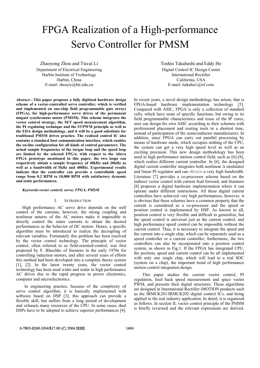
system, as shown in Fig.1. If the FPGA has integrated CPU,
the position, speed and current control can be all implemented
with only one single chip, which will lead to a real SOC
(system on a chip), the important trend of high performance
motion control integration design.
This paper studies
the current vector control, PI
regulation, feed back speed measurement and space vector
PWM, and presents their digital structures. These algorithms
are designed in International Rectifier iMOTION products such
as the IRMCK201/IRMCK202 digital control ICs, and being
applied to the real industry application. In detail, it is organized
as follows. In section II, vector control principle of the PMSM
is briefly reviewed and the relevant expressions are derived.
0-7803-8269-2/04/$17.00 (C) 2004 IEEE.
1604
�
Section III describes the design scheme of the digital hardware.
Section IV implements the circuits on an Altera FPGA and
shows the experimental results. In section V some conclusions
are drawn.
II. BASIC PRINCIPLE OF THE ROTOR-FLUX-ORIENTED
VECTOR CONTROL
For a PMSM with surface-mounted magnets that generate a
constant flux-linkage with the stator windings, the typical
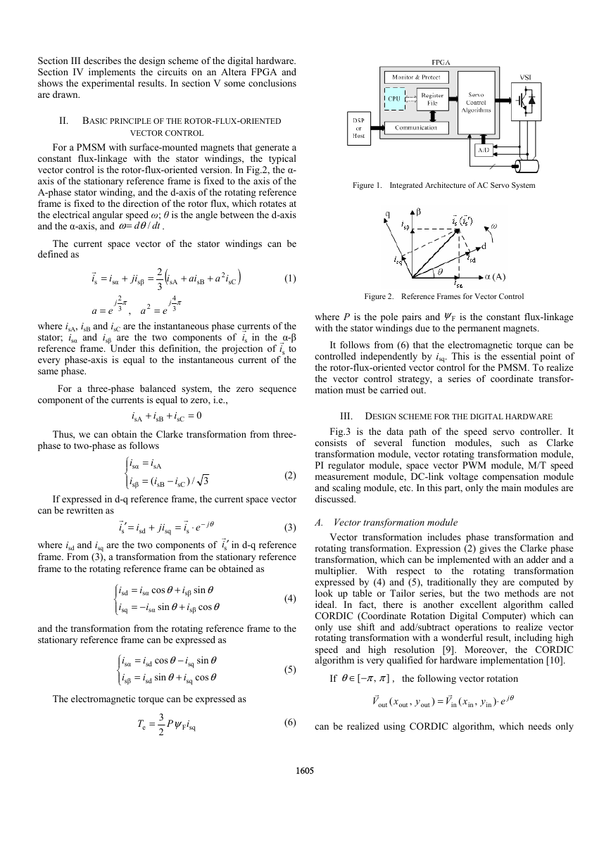
vector control is the rotor-flux-oriented version. In Fig.2, the α-
axis of the stationary reference frame is fixed to the axis of the
A-phase stator winding, and the d-axis of the rotating reference
frame is fixed to the direction of the rotor flux, which rotates at
the electrical angular speed ω; θ is the angle between the d-axis
and the α-axis, and .
d /θω=
dt
The current space vector of the stator windings can be
defined as
=r
i
s
i
sα
+
ji
sβ
=
+
ai
sB
+
2
ia
sC
sA
)
(
i
2
3
(1)
j
2
3
π
,
a
=
e
π
j
4
3
2
a
=
e
where isA, isB and isC are the instantaneous phase currents of the
stator; isα and isβ are the two components of in the α-β
reference frame. Under this definition, the projection of to
every phase-axis is equal to the instantaneous current of the
same phase.
sir
sir
For a three-phase balanced system, the zero sequence
component of the currents is equal to zero, i.e.,
Thus, we can obtain the Clarke transformation from three-
i
sA
+
i
sB
+
i
sC
=
0
phase to two-phase as follows
i
sα
i
sβ
=
=
i
sA
i
(
sB
−
i
sC
3/)
(2)
If expressed in d-q reference frame, the current space vector
can be rewritten as
+
r
=′
i
s
ji
i
sd
(3)
where isd and isq are the two components of in d-q reference
frame. From (3), a transformation from the stationary reference
frame to the rotating reference frame can be obtained as
si ′r
sq
−⋅=
r
θjei
s
i
sd
i
sq
=
i
sα
−=
i
sα
θ
+
i
cos
sβ
θ
+
i
sin
sβ
θ
sin
(4)
θ
cos
and the transformation from the rotating reference frame to the
stationary reference frame can be expressed as
i
sα
i
sβ
=
=
i
sd
i
sd
cos
sin
θ
−
i
sq
θ
+
i
sq
sin
cos
θ
(5)
θ
The electromagnetic torque can be expressed as
Figure 1. Integrated Architecture of AC Servo System
Figure 2. Reference Frames for Vector Control
where P is the pole pairs and is the constant flux-linkage
with the stator windings due to the permanent magnets.
Fψ
It follows from (6) that the electromagnetic torque can be
controlled independently by isq. This is the essential point of
the rotor-flux-oriented vector control for the PMSM. To realize
the vector control strategy, a series of coordinate transfor-
mation must be carried out.
III. DESIGN SCHEME FOR THE DIGITAL HARDWARE
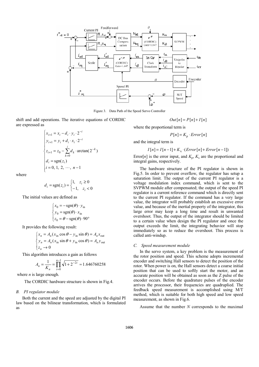
Fig.3 is the data path of the speed servo controller. It
consists of several function modules, such as Clarke
transformation module, vector rotating transformation module,
PI regulator module, space vector PWM module, M/T speed
measurement module, DC-link voltage compensation module
and scaling module, etc. In this part, only the main modules are
discussed.
A. Vector transformation module
to
the rotating
Vector transformation includes phase transformation and
rotating transformation. Expression (2) gives the Clarke phase
transformation, which can be implemented with an adder and a
multiplier. With respect
transformation
expressed by (4) and (5), traditionally they are computed by
look up table or Tailor series, but the two methods are not
ideal. In fact, there is another excellent algorithm called
CORDIC (Coordinate Rotation Digital Computer) which can
only use shift and add/subtract operations to realize vector
rotating transformation with a wonderful result, including high
speed and high resolution [9]. Moreover, the CORDIC
algorithm is very qualified for hardware implementation [10].
,
[ ππθ −∈
]
If ,the following vector rotation
θje
=
r
xV
(
in
r
V
out
out
out
y
y
⋅
)
(
x
in
,
in
)
,
T
e
ψ=
P
i
sqF
3
2
(6)
can be realized using CORDIC algorithm, which needs only
1605
�
Figure 3. Data Path of the Speed Servo Controller
+
nI
][
nP
][
⋅
Error
n
][
nOut
][
=
where the proportional term is
K
nP
][
and the integral term is
+−
]1
nI
][
nI
[
K
=
=
p
−
+
1
=
=
x
i
y
x
i
y
−
+
shift and add operations. The iterative equations of CORDIC
are expressed as
d
i
⋅
d
y
i
i
⋅
xd
i
i
∑
d
=
k
0
)
,
+
1
=
z
sgn(
,2,1,0
arctan(
−
k
)2
2
2
i
=
L
⋅
⋅
+
1
−
−
=
n
1
z
z
−
⋅
0
k
i
i
i
i
i
i
i
where
=
d
i
sgn(
z
)
i
=
z
i
≥
z
i
0
<
0
,1
,1
−
in
y
x
0
y
z
−=
=
sgn(
θ
−=
The initial values are defined as
θ
⋅
sgn(
)
θ
⋅
x
)
in
θ
⋅
90)
sgn(
It provides the following result:
y
y
sin
cos
cos
sin
in
0
0
in
x
n
y
z
n
n
=
=
→
xA
(
n
in
xA
(
n
0
in
−
θ
+
θ
°
θ
)
θ
)
=
=
xA
n
yA
n
out
out
This algorithm introduces a gain as follows
n
∏−
=
0
where n is large enough.
1
=
A
n K
=
n
i
1
+
21
−
2 ≈
i
.1
646760258
The CORDIC hardware structure is shown in Fig.4.
B. PI regulator module
Both the current and the speed are adjusted by the digital PI
law based on the bilinear transformation, which is formulated
as
1606
⋅
x
(
Error
n
][
+
Error
[
n
−
])1
Error[n] is the error input, and Kp, Kx are the proportional and
integral gains, respectively.
The hardware structure of the PI regulator is shown in
Fig.5. In order to prevent overflow, the regulator has setup a
saturation limit. The output of the current PI regulator is a
voltage modulation index command, which is sent to the
SVPWM module after compensated; the output of the speed PI
regulator is a current reference command which is directly sent
to the current PI regulator. If the command has a very large
value, the integrator will probably establish an excessive error
value, and because of the inertial property of the integrator, this
large error may keep a long time and result in unwanted
overshoot. Thus, the output of the integrator should be limited
to a certain value when design the PI regulator and once the
output exceeds the limit, the integrating behavior will stop
immediately so as to reduce the overshoot. This process is
called anti-windup.
C. Speed measurement module
In the servo system, a key problem is the measurement of
the rotor position and speed. This scheme adopts incremental
encoder and switching Hall sensors to detect the position of the
rotor. When power is on, the Hall sensors detect a coarse initial
position that can be used to softly start the motor, and an
accurate position will be obtained as soon as the Z pulse of the
encoder occurs. Before the quadrature pulses of the encoder
arrives the processor, their frequencies are quadruplied. The
feedback speed measurement is accomplished using M/T
method, which is suitable for both high speed and low speed
measurement, as shown in Fig.6.
Assume that the number N corresponds to the maximal
�
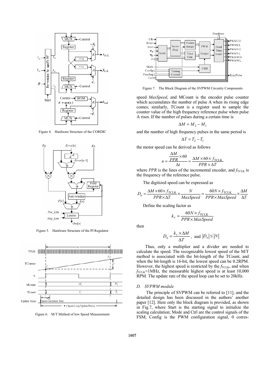
Figure 7. The Block Diagram of the SVPWM Circuitry Components
speed MaxSpeed, and MCount is the encoder pulse counter
which accumulates the number of pulse A when its rising edge
comes; similarly, TCount is a register used to sample the
counter value of the high frequency reference pulse when pulse
A rises. If the number of pulses during a certain time is
and the number of high frequency pulses in the same period is
the motor speed can be derived as follows
2 MMM
−
2 T
T
1
=∆
T
∆
−
=
1
=
n
∆
M
PPR
∆
t
×
60
×∆=
M
60
PPR
×
f
TCLK
∆×
T
Figure 4. Hardware Structure of the CORDIC
where PPR is the lines of the incremental encoder, and fTCLK is
the frequency of the reference pulse.
The digitized speed can be expressed as
×∆=
M
60
60
PPR
PPR
×
f
TCLK
∆×
T
MaxSpeed
N
=
×
×
fN
×
MaxSpeed
TCLK
Dn
∆×
M
∆
T
Define the scaling factor as
60
PPR
=
k
v
×
fN
×
MaxSpeed
TCLK
Figure 5. Hardware Structure of the PI Regulator
then
k
= v
Dn
M
∆×
∆
T
, and
Dn ≤
N
Thus, only a multiplier and a divider are needed to
calculate the speed. The recognizable lowest speed of the M/T
method is associated with the bit-length of the TCount, and
when the bit-length is 16-bit, the lowest speed can be 0.2RPM.
However, the highest speed is restricted by the fTCLK, and when
fTCLK=1MHz, the measurable highest speed is at least 10,000
RPM. The update rate of the speed loop can be set to 20kHz.
D. SVPWM module
The principle of SVPWM can be referred to [11], and the
detailed design has been discussed in the authors’ another
paper [12]. Here only the block diagram is provided, as shown
in Fig.7, where Start is the starting signal to initialize the
scaling calculation; Mode and Ctrl are the control signals of the
FSM; Config is the PWM configuration signal, 0 corres-
Figure 6. M/T Method of low Speed Measurement
1607
�
ponding to the asymmetrical mode and 1 corresponding to the
symmetrical mode; mα and mβ are the modulation indexes in
stationary reference frame coming from the digital current PI
regulator; k is the scaling factor to transform the indexes to
time values; FreqReg is the switching frequency register.
Besides the above modules, there are other auxiliary
function modules, such as communication, configuration and
status register file, monitor and protection, etc. All these
modules constitute a complete single-chip servo controller.
IV. FPGA IMPLEMENTATION AND EXPERIMENTAL RESULTS
Each module of the servo controller is described with
Verilog HDL and synthesized with Synplify® software. After
placement and routing in Quartus II environment, the controller
IC is implemented on one-chip Altera Cyclone EP1C20F400
FPGA, and the total ATOM counts for this design are about
7492 of total 20060 (37%). The design summary is given in
Table I.
The designed IC can operate at 40MHz system clock, and
all kinds of control parameters can be accessed via the
communication port on-line by a host. This IC can be
considered as either a slave device that can interface with the
DSP and other circuits to construct a complete position servo
control system, or an IP core which can be integrated into a
motion control SOC with the IP core of CPU. This SOC style
of motion control can greatly reduce the area of a PCB of the
whole system and improve its immunity to interferences.
To test the performance of the servo controller, a 1.5kW
PMSM with maximal speed of 5000RPM and PPR of 5000 is
driven under a sample
frequency with 10kHz. The
experimental speed traces, as well as modulation index curves
of the stationary reference frame, under different commands
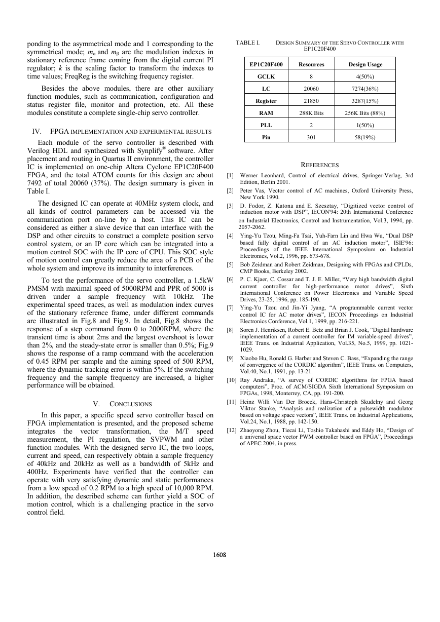
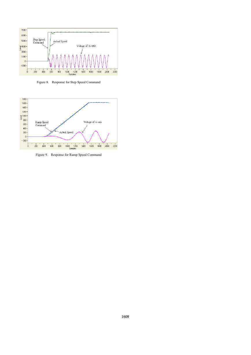
are illustrated in Fig.8 and Fig.9. In detail, Fig.8 shows the
response of a step command from 0 to 2000RPM, where the
transient time is about 2ms and the largest overshoot is lower
than 2%, and the steady-state error is smaller than 0.5%; Fig.9
shows the response of a ramp command with the acceleration
of 0.45 RPM per sample and the aiming speed of 500 RPM,
where the dynamic tracking error is within 5%. If the switching
frequency and the sample frequency are increased, a higher
performance will be obtained.
V. CONCLUSIONS
the M/T
the vector
transformation,
In this paper, a specific speed servo controller based on
FPGA implementation is presented, and the proposed scheme
integrates
speed
measurement, the PI regulation, the SVPWM and other
function modules. With the designed servo IC, the two loops,
current and speed, can respectively obtain a sample frequency
of 40kHz and 20kHz as well as a bandwidth of 5kHz and
400Hz. Experiments have verified that the controller can
operate with very satisfying dynamic and static performances
from a low speed of 0.2 RPM to a high speed of 10,000 RPM.
In addition, the described scheme can further yield a SOC of
motion control, which is a challenging practice in the servo
control field.
1608
TABLE I.
DESIGN SUMMARY OF THE SERVO CONTROLLER WITH
EP1C20F400
EP1C20F400
Resources
Design Usage
GCLK
LC
Register
RAM
PLL
Pin
8
20060
21850
4(50%)
7274(36%)
3287(15%)
288K Bits
256K Bits (88%)
2
301
1(50%)
58(19%)
REFERENCES
[1] Werner Leonhard, Control of electrical drives, Springer-Verlag, 3rd
Edition, Berlin 2001.
[2] Peter Vas, Vector control of AC machines, Oxford University Press,
New York 1990.
[3] D. Fodor, Z. Katona and E. Szesztay, “Digitized vector control of
induction motor with DSP”, IECON'94: 20th International Conference
on Industrial Electronics, Control and Instrumentation, Vol.3, 1994, pp.
2057-2062.
[4] Ying-Yu Tzou, Ming-Fa Tsai, Yuh-Farn Lin and Hwa Wu, “Dual DSP
based fully digital control of an AC induction motor”, ISIE'96:
Proceedings of the IEEE International Symposium on Industrial
Electronics, Vol.2, 1996, pp. 673-678.
[5] Bob Zeidman and Robert Zeidman, Designing with FPGAs and CPLDs,
CMP Books, Berkeley 2002.
[6] P. C. Kjaer, C. Cossar and T. J. E. Miller, “Very high bandwidth digital
current controller
for high-performance motor drives”, Sixth
International Conference on Power Electronics and Variable Speed
Drives, 23-25, 1996, pp. 185-190.
[7] Ying-Yu Tzou and Jin-Yi Jyang, “A programmable current vector
control IC for AC motor drives”, IECON Proceedings on Industrial
Electronics Conference, Vol.1, 1999, pp. 216-221.
[8] Soren J. Henriksen, Robert E. Betz and Brian J. Cook, “Digital hardware
implementation of a current controller for IM variable-speed drives”,
IEEE Trans. on Industrial Application, Vol.35, No.5, 1999, pp. 1021-
1029.
[9] Xiaobo Hu, Ronald G. Harber and Steven C. Bass, “Expanding the range
of convergence of the CORDIC algorithm”, IEEE Trans. on Computers,
Vol.40, No.1, 1991, pp. 13-21.
[10] Ray Andraka, “A survey of CORDIC algorithms for FPGA based
computers”, Proc. of ACM/SIGDA Sixth International Symposium on
FPGAs, 1998, Monterrey, CA, pp. 191-200.
[11] Heinz Willi Van Der Broeck, Hans-Christoph Skudelny and Georg
Viktor Stanke, “Analysis and realization of a pulsewidth modulator
based on voltage space vectors”, IEEE Trans. on Industrial Applications,
Vol.24, No.1, 1988, pp. 142-150.
[12] Zhaoyong Zhou, Tiecai Li, Toshio Takahashi and Eddy Ho, “Design of
a universal space vector PWM controller based on FPGA”, Proceedings
of APEC 2004, in press.
�
Figure 8. Response for Step Speed Command
Figure 9. Response for Ramp Speed Command
1609
�


 2023年江西萍乡中考道德与法治真题及答案.doc
 2012年重庆南川中考生物真题及答案.doc
 2013年江西师范大学地理学综合及文艺理论基础考研真题.doc
 2020年四川甘孜小升初语文真题及答案I卷.doc
 2020年注册岩土工程师专业基础考试真题及答案.doc
 2023-2024学年福建省厦门市九年级上学期数学月考试题及答案.doc
 2021-2022学年辽宁省沈阳市大东区九年级上学期语文期末试题及答案.doc
 2022-2023学年北京东城区初三第一学期物理期末试卷及答案.doc
 2018上半年江西教师资格初中地理学科知识与教学能力真题及答案.doc
 2012年河北国家公务员申论考试真题及答案-省级.doc
 2020-2021学年江苏省扬州市江都区邵樊片九年级上学期数学第一次质量检测试题及答案.doc
 2022下半年黑龙江教师资格证中学综合素质真题及答案.doc