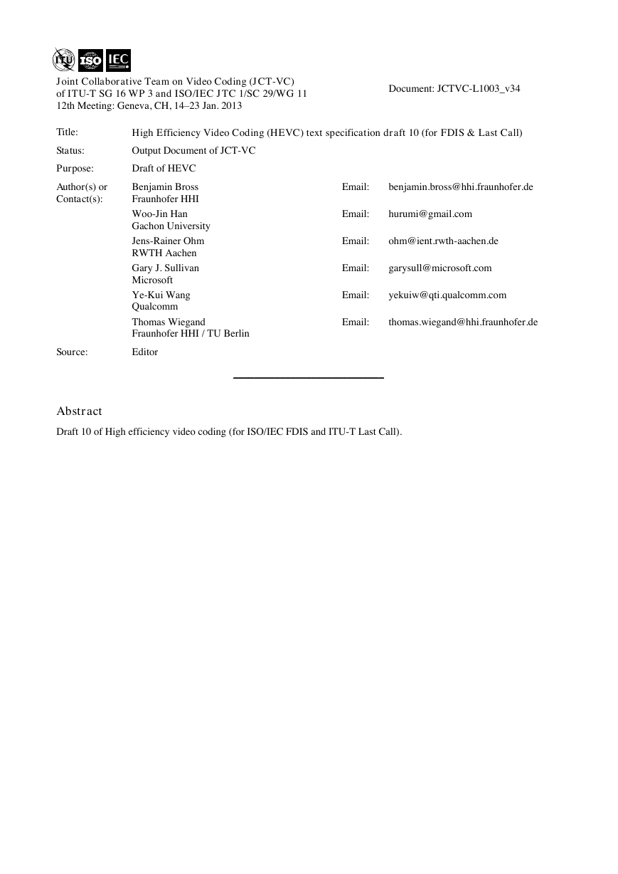
Joint Collaborative Team on Video Coding (JCT-VC)
of ITU-T SG 16 WP 3 and ISO/IEC JTC 1/SC 29/WG 11
12th Meeting: Geneva, CH, 14–23 Jan. 2013
Document: JCTVC-L1003_v34
Title:
Status:
High Efficiency Video Coding (HEVC) text specification draft 10 (for FDIS & Last Call)
Output Document of JCT-VC
Purpose:
Draft of HEVC
Author(s) or
Contact(s):
Benjamin Bross
Fraunhofer HHI
Woo-Jin Han
Gachon University
Jens-Rainer Ohm
RWTH Aachen
Gary J. Sullivan
Microsoft
Ye-Kui Wang
Qualcomm
Thomas Wiegand
Fraunhofer HHI / TU Berlin
Source:
Editor
Email:
Email:
Email:
Email:
Email:
Email:
benjamin.bross@hhi.fraunhofer.de
hurumi@gmail.com
ohm@ient.rwth-aachen.de
garysull@microsoft.com
yekuiw@qti.qualcomm.com
thomas.wiegand@hhi.fraunhofer.de
_____________________________
Abstract
Draft 10 of High efficiency video coding (for ISO/IEC FDIS and ITU-T Last Call).
�
Draft ISO/IEC 23008-2 : 201x (E)
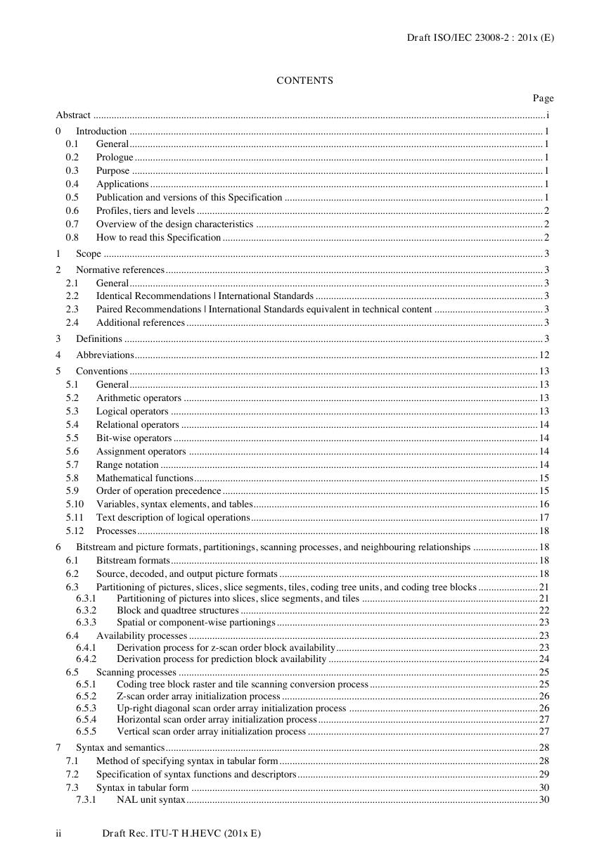
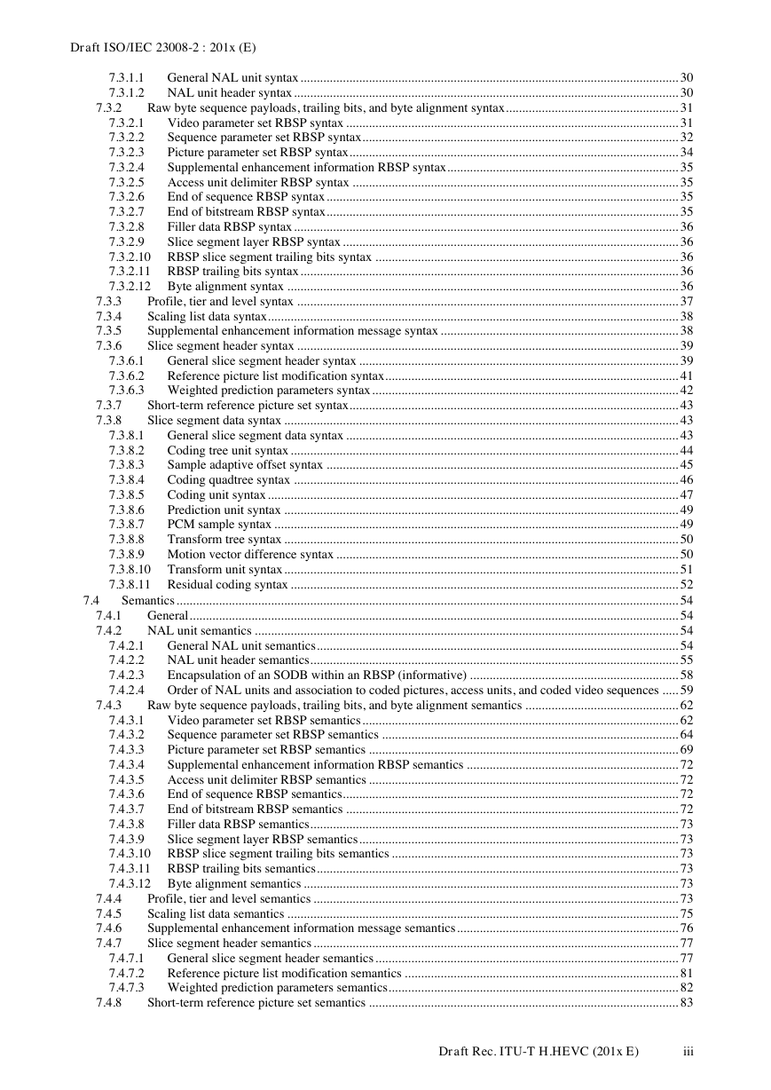
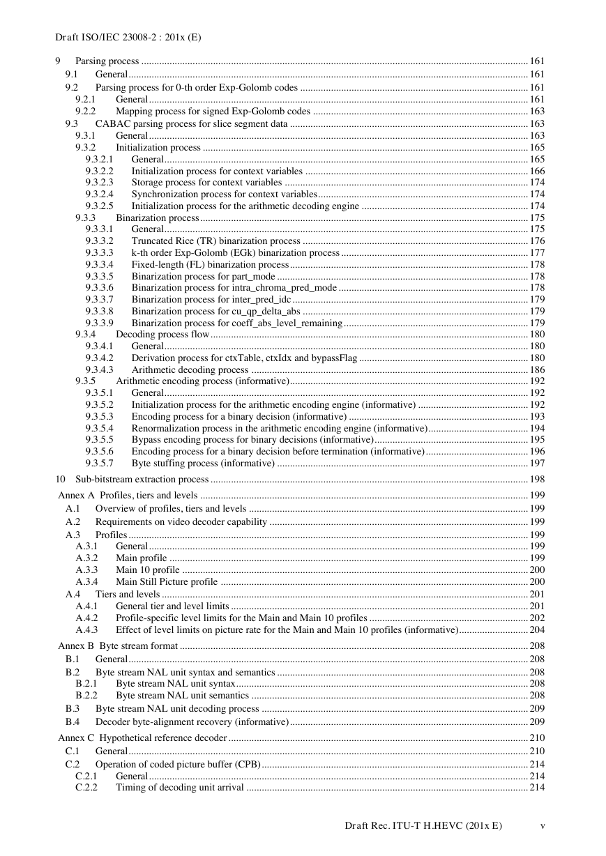
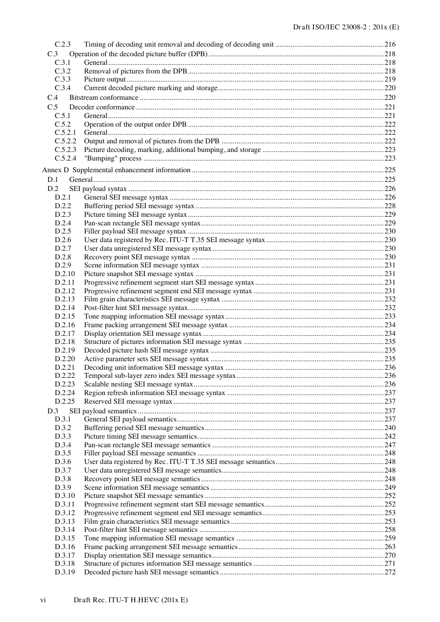
CONTENTS
2.1
2.2
2.3
2.4
0.1
0.2
0.3
0.4
0.5
0.6
0.7
0.8
Page
Abstract ............................................................................................................................................................................... i
0
Introduction ................................................................................................................................................................ 1
General ................................................................................................................................................................ 1
Prologue .............................................................................................................................................................. 1
Purpose ............................................................................................................................................................... 1
Applications ........................................................................................................................................................ 1
Publication and versions of this Specification .................................................................................................... 1
Profiles, tiers and levels ...................................................................................................................................... 2
Overview of the design characteristics ............................................................................................................... 2
How to read this Specification ............................................................................................................................ 2
1
Scope .......................................................................................................................................................................... 3
2 Normative references .................................................................................................................................................. 3
General ................................................................................................................................................................ 3
Identical Recommendations | International Standards ........................................................................................ 3
Paired Recommendations | International Standards equivalent in technical content .......................................... 3
Additional references .......................................................................................................................................... 3
3 Definitions .................................................................................................................................................................. 3
4 Abbreviations ............................................................................................................................................................ 12
5 Conventions .............................................................................................................................................................. 13
General .............................................................................................................................................................. 13
5.1
Arithmetic operators ......................................................................................................................................... 13
5.2
Logical operators .............................................................................................................................................. 13
5.3
Relational operators .......................................................................................................................................... 14
5.4
Bit-wise operators ............................................................................................................................................. 14
5.5
Assignment operators ....................................................................................................................................... 14
5.6
5.7
Range notation .................................................................................................................................................. 14
5.8 Mathematical functions ..................................................................................................................................... 15
5.9
Order of operation precedence .......................................................................................................................... 15
5.10 Variables, syntax elements, and tables .............................................................................................................. 16
5.11 Text description of logical operations ............................................................................................................... 17
5.12 Processes ........................................................................................................................................................... 18
6 Bitstream and picture formats, partitionings, scanning processes, and neighbouring relationships ......................... 18
Bitstream formats .............................................................................................................................................. 18
Source, decoded, and output picture formats .................................................................................................... 18
Partitioning of pictures, slices, slice segments, tiles, coding tree units, and coding tree blocks ....................... 21
Partitioning of pictures into slices, slice segments, and tiles .................................................................... 21
Block and quadtree structures ................................................................................................................... 22
Spatial or component-wise partionings ..................................................................................................... 23
Availability processes ....................................................................................................................................... 23
Derivation process for z-scan order block availability .............................................................................. 23
Derivation process for prediction block availability ................................................................................. 24
Scanning processes ........................................................................................................................................... 25
Coding tree block raster and tile scanning conversion process ................................................................. 25
6.5.1
Z-scan order array initialization process ................................................................................................... 26
6.5.2
Up-right diagonal scan order array initialization process ......................................................................... 26
6.5.3
Horizontal scan order array initialization process ..................................................................................... 27
6.5.4
6.5.5
Vertical scan order array initialization process ......................................................................................... 27
Syntax and semantics ................................................................................................................................................ 28
7.1 Method of specifying syntax in tabular form .................................................................................................... 28
Specification of syntax functions and descriptors ............................................................................................. 29
7.2
Syntax in tabular form ...................................................................................................................................... 30
7.3
NAL unit syntax ........................................................................................................................................ 30
6.3.1
6.3.2
6.3.3
6.4.1
6.4.2
7.3.1
6.1
6.2
6.3
6.4
6.5
7
ii
Draft Rec. ITU-T H.HEVC (201x E)
�
Draft ISO/IEC 23008-2 : 201x (E)
7.3.2
7.3.3
7.3.4
7.3.5
7.3.6
7.3.7
7.3.8
7.4
7.4.1
7.4.2
7.4.3
7.3.1.1
7.3.1.2
General NAL unit syntax .................................................................................................................... 30
NAL unit header syntax ...................................................................................................................... 30
Raw byte sequence payloads, trailing bits, and byte alignment syntax ..................................................... 31
Video parameter set RBSP syntax ...................................................................................................... 31
7.3.2.1
Sequence parameter set RBSP syntax ................................................................................................. 32
7.3.2.2
Picture parameter set RBSP syntax ..................................................................................................... 34
7.3.2.3
Supplemental enhancement information RBSP syntax ....................................................................... 35
7.3.2.4
Access unit delimiter RBSP syntax .................................................................................................... 35
7.3.2.5
End of sequence RBSP syntax ............................................................................................................ 35
7.3.2.6
End of bitstream RBSP syntax ............................................................................................................ 35
7.3.2.7
Filler data RBSP syntax ...................................................................................................................... 36
7.3.2.8
7.3.2.9
Slice segment layer RBSP syntax ....................................................................................................... 36
7.3.2.10 RBSP slice segment trailing bits syntax ............................................................................................. 36
7.3.2.11 RBSP trailing bits syntax .................................................................................................................... 36
7.3.2.12 Byte alignment syntax ........................................................................................................................ 36
Profile, tier and level syntax ..................................................................................................................... 37
Scaling list data syntax .............................................................................................................................. 38
Supplemental enhancement information message syntax ......................................................................... 38
Slice segment header syntax ..................................................................................................................... 39
General slice segment header syntax .................................................................................................. 39
7.3.6.1
7.3.6.2
Reference picture list modification syntax .......................................................................................... 41
7.3.6.3 Weighted prediction parameters syntax .............................................................................................. 42
Short-term reference picture set syntax ..................................................................................................... 43
Slice segment data syntax ......................................................................................................................... 43
General slice segment data syntax ...................................................................................................... 43
7.3.8.1
Coding tree unit syntax ....................................................................................................................... 44
7.3.8.2
Sample adaptive offset syntax ............................................................................................................ 45
7.3.8.3
Coding quadtree syntax ...................................................................................................................... 46
7.3.8.4
Coding unit syntax .............................................................................................................................. 47
7.3.8.5
Prediction unit syntax ......................................................................................................................... 49
7.3.8.6
PCM sample syntax ............................................................................................................................ 49
7.3.8.7
7.3.8.8
Transform tree syntax ......................................................................................................................... 50
7.3.8.9 Motion vector difference syntax ......................................................................................................... 50
7.3.8.10 Transform unit syntax ......................................................................................................................... 51
7.3.8.11 Residual coding syntax ....................................................................................................................... 52
Semantics .......................................................................................................................................................... 54
General ...................................................................................................................................................... 54
NAL unit semantics .................................................................................................................................. 54
General NAL unit semantics ............................................................................................................... 54
NAL unit header semantics ................................................................................................................. 55
Encapsulation of an SODB within an RBSP (informative) ................................................................ 58
Order of NAL units and association to coded pictures, access units, and coded video sequences ..... 59
Raw byte sequence payloads, trailing bits, and byte alignment semantics ............................................... 62
Video parameter set RBSP semantics ................................................................................................. 62
7.4.3.1
Sequence parameter set RBSP semantics ........................................................................................... 64
7.4.3.2
Picture parameter set RBSP semantics ............................................................................................... 69
7.4.3.3
Supplemental enhancement information RBSP semantics ................................................................. 72
7.4.3.4
Access unit delimiter RBSP semantics ............................................................................................... 72
7.4.3.5
End of sequence RBSP semantics ....................................................................................................... 72
7.4.3.6
End of bitstream RBSP semantics ...................................................................................................... 72
7.4.3.7
Filler data RBSP semantics ................................................................................................................. 73
7.4.3.8
7.4.3.9
Slice segment layer RBSP semantics .................................................................................................. 73
7.4.3.10 RBSP slice segment trailing bits semantics ........................................................................................ 73
7.4.3.11 RBSP trailing bits semantics ............................................................................................................... 73
7.4.3.12 Byte alignment semantics ................................................................................................................... 73
Profile, tier and level semantics ................................................................................................................ 73
Scaling list data semantics ........................................................................................................................ 75
Supplemental enhancement information message semantics .................................................................... 76
Slice segment header semantics ................................................................................................................ 77
General slice segment header semantics ............................................................................................. 77
7.4.7.1
7.4.7.2
Reference picture list modification semantics .................................................................................... 81
7.4.7.3 Weighted prediction parameters semantics ......................................................................................... 82
Short-term reference picture set semantics ............................................................................................... 83
7.4.2.1
7.4.2.2
7.4.2.3
7.4.2.4
7.4.4
7.4.5
7.4.6
7.4.7
7.4.8
Draft Rec. ITU-T H.HEVC (201x E)
iii
�
Draft ISO/IEC 23008-2 : 201x (E)
7.4.9
8.1
8.2
8.3
8.4.4.1
8.4.4.2
8.3.1
8.3.2
8.3.3
8.3.3.1
8.3.3.2
8.3.4
8.4
8.4.1
8.4.2
8.4.3
8.4.4
Slice segment data semantics .................................................................................................................... 85
General slice segment data semantics ................................................................................................. 85
7.4.9.1
Coding tree unit semantics .................................................................................................................. 85
7.4.9.2
Sample adaptive offset semantics ....................................................................................................... 85
7.4.9.3
Coding quadtree semantics ................................................................................................................. 87
7.4.9.4
Coding unit semantics ......................................................................................................................... 87
7.4.9.5
Prediction unit semantics .................................................................................................................... 89
7.4.9.6
PCM sample semantics ....................................................................................................................... 90
7.4.9.7
7.4.9.8
Transform tree semantics .................................................................................................................... 90
7.4.9.9 Motion vector difference semantics .................................................................................................... 91
7.4.9.10 Transform unit semantics .................................................................................................................... 91
7.4.9.11 Residual coding semantics .................................................................................................................. 92
8 Decoding process ...................................................................................................................................................... 94
General decoding process ................................................................................................................................. 94
NAL unit decoding process .............................................................................................................................. 95
Slice decoding process ...................................................................................................................................... 96
Decoding process for picture order count ................................................................................................. 96
Decoding process for reference picture set ............................................................................................... 96
Decoding process for generating unavailable reference pictures ............................................................ 100
General decoding process for generating unavailable reference pictures ......................................... 100
Generation of one unavailable picture .............................................................................................. 101
Decoding process for reference picture lists construction ....................................................................... 101
Decoding process for coding units coded in intra prediction mode ................................................................ 102
General decoding process for coding units coded in intra prediction mode ........................................... 102
Derivation process for luma intra prediction mode ................................................................................. 103
Derivation process for chroma intra prediction mode ............................................................................. 105
Decoding process for intra blocks ........................................................................................................... 105
General decoding process for intra blocks ........................................................................................ 105
Intra sample prediction ..................................................................................................................... 106
Decoding process for coding units coded in inter prediction mode ................................................................ 112
General decoding process for coding units coded in inter prediction mode ........................................... 112
Inter prediction process ........................................................................................................................... 112
Decoding process for prediction units in inter prediction mode ............................................................. 115
General .............................................................................................................................................. 115
Derivation process for motion vector components and reference indices ......................................... 115
Decoding process for inter prediction samples ................................................................................. 130
Decoding process for the residual signal of coding units coded in inter prediction mode ...................... 138
General .............................................................................................................................................. 138
Decoding process for luma residual blocks ...................................................................................... 139
Decoding process for chroma residual blocks .................................................................................. 140
Scaling, transformation and array construction process prior to deblocking filter process ............................. 141
Derivation process for quantization parameters ...................................................................................... 141
Scaling and transformation process ........................................................................................................ 142
Scaling process for transform coefficients .............................................................................................. 143
Transformation process for scaled transform coefficients ...................................................................... 144
General .............................................................................................................................................. 144
Transformation process ..................................................................................................................... 144
Picture construction process prior to in-loop filter process ..................................................................... 146
In-loop filter process ....................................................................................................................................... 146
General .................................................................................................................................................... 146
Deblocking filter process ........................................................................................................................ 147
General .............................................................................................................................................. 147
Derivation process of transform block boundary .............................................................................. 148
Derivation process of prediction block boundary ............................................................................. 149
Derivation process of boundary filtering strength ............................................................................ 150
Edge filtering process ....................................................................................................................... 151
Sample adaptive offset process ............................................................................................................... 159
General .............................................................................................................................................. 159
Coding tree block modification process ............................................................................................ 159
8.7.2.1
8.7.2.2
8.7.2.3
8.7.2.4
8.7.2.5
8.6.1
8.6.2
8.6.3
8.6.4
8.7
8.6.5
8.7.1
8.7.2
8.5.3.1
8.5.3.2
8.5.3.3
8.5.4.1
8.5.4.2
8.5.4.3
8.7.3
8.7.3.1
8.7.3.2
8.5
8.5.1
8.5.2
8.5.3
8.5.4
8.6
8.6.4.1
8.6.4.2
iv
Draft Rec. ITU-T H.HEVC (201x E)
�
Draft ISO/IEC 23008-2 : 201x (E)
9
9.3.1
9.3.2
9.3.3
9.3.4
9.3.5
9.1
9.2
9.3
9.3.4.1
9.3.4.2
9.3.4.3
9.3.5.1
9.3.5.2
9.3.5.3
9.3.5.4
9.3.5.5
9.3.5.6
9.3.5.7
9.3.2.1
9.3.2.2
9.3.2.3
9.3.2.4
9.3.2.5
9.3.3.1
9.3.3.2
9.3.3.3
9.3.3.4
9.3.3.5
9.3.3.6
9.3.3.7
9.3.3.8
9.3.3.9
Parsing process ....................................................................................................................................................... 161
General ............................................................................................................................................................ 161
Parsing process for 0-th order Exp-Golomb codes ......................................................................................... 161
9.2.1
General .................................................................................................................................................... 161
9.2.2 Mapping process for signed Exp-Golomb codes .................................................................................... 163
CABAC parsing process for slice segment data ............................................................................................. 163
General .................................................................................................................................................... 163
Initialization process ............................................................................................................................... 165
General .............................................................................................................................................. 165
Initialization process for context variables ....................................................................................... 166
Storage process for context variables ............................................................................................... 174
Synchronization process for context variables .................................................................................. 174
Initialization process for the arithmetic decoding engine ................................................................. 174
Binarization process ................................................................................................................................ 175
General .............................................................................................................................................. 175
Truncated Rice (TR) binarization process ........................................................................................ 176
k-th order Exp-Golomb (EGk) binarization process ......................................................................... 177
Fixed-length (FL) binarization process ............................................................................................. 178
Binarization process for part_mode .................................................................................................. 178
Binarization process for intra_chroma_pred_mode .......................................................................... 178
Binarization process for inter_pred_idc ............................................................................................ 179
Binarization process for cu_qp_delta_abs ........................................................................................ 179
Binarization process for coeff_abs_level_remaining ........................................................................ 179
Decoding process flow ............................................................................................................................ 180
General .............................................................................................................................................. 180
Derivation process for ctxTable, ctxIdx and bypassFlag .................................................................. 180
Arithmetic decoding process ............................................................................................................ 186
Arithmetic encoding process (informative)............................................................................................. 192
General .............................................................................................................................................. 192
Initialization process for the arithmetic encoding engine (informative) ........................................... 192
Encoding process for a binary decision (informative) ...................................................................... 193
Renormalization process in the arithmetic encoding engine (informative) ....................................... 194
Bypass encoding process for binary decisions (informative) ............................................................ 195
Encoding process for a binary decision before termination (informative) ........................................ 196
Byte stuffing process (informative) .................................................................................................. 197
10 Sub-bitstream extraction process ............................................................................................................................ 198
Annex A Profiles, tiers and levels ................................................................................................................................ 199
A.1 Overview of profiles, tiers and levels ............................................................................................................. 199
A.2 Requirements on video decoder capability ..................................................................................................... 199
A.3
Profiles ............................................................................................................................................................ 199
A.3.1
General .................................................................................................................................................... 199
A.3.2 Main profile ............................................................................................................................................ 199
A.3.3 Main 10 profile ....................................................................................................................................... 200
A.3.4 Main Still Picture profile ........................................................................................................................ 200
Tiers and levels ............................................................................................................................................... 201
General tier and level limits .................................................................................................................... 201
Profile-specific level limits for the Main and Main 10 profiles .............................................................. 202
Effect of level limits on picture rate for the Main and Main 10 profiles (informative)........................... 204
Annex B Byte stream format ........................................................................................................................................ 208
B.1 General ............................................................................................................................................................ 208
B.2 Byte stream NAL unit syntax and semantics .................................................................................................. 208
Byte stream NAL unit syntax .................................................................................................................. 208
Byte stream NAL unit semantics ............................................................................................................ 208
B.3 Byte stream NAL unit decoding process ........................................................................................................ 209
B.4 Decoder byte-alignment recovery (informative) ............................................................................................. 209
Annex C Hypothetical reference decoder ..................................................................................................................... 210
C.1 General ............................................................................................................................................................ 210
C.2 Operation of coded picture buffer (CPB) ........................................................................................................ 214
General .................................................................................................................................................... 214
Timing of decoding unit arrival .............................................................................................................. 214
A.4
A.4.1
A.4.2
A.4.3
B.2.1
B.2.2
C.2.1
C.2.2
Draft Rec. ITU-T H.HEVC (201x E)
v
�
Draft ISO/IEC 23008-2 : 201x (E)
C.2.3
C.3.1
C.3.2
C.3.3
C.3.4
Timing of decoding unit removal and decoding of decoding unit .......................................................... 216
C.3 Operation of the decoded picture buffer (DPB) .............................................................................................. 218
General .................................................................................................................................................... 218
Removal of pictures from the DPB ......................................................................................................... 218
Picture output .......................................................................................................................................... 219
Current decoded picture marking and storage ......................................................................................... 220
C.4 Bitstream conformance ................................................................................................................................... 220
C.5 Decoder conformance ..................................................................................................................................... 221
General .................................................................................................................................................... 221
C.5.1
C.5.2
Operation of the output order DPB ......................................................................................................... 222
C.5.2.1 General .................................................................................................................................................... 222
C.5.2.2 Output and removal of pictures from the DPB ....................................................................................... 222
C.5.2.3 Picture decoding, marking, additional bumping, and storage ................................................................. 223
C.5.2.4 "Bumping" process ................................................................................................................................. 223
Annex D Supplemental enhancement information ....................................................................................................... 225
D.1 General ............................................................................................................................................................ 225
SEI payload syntax ......................................................................................................................................... 226
D.2
General SEI message syntax ................................................................................................................... 226
D.2.1
Buffering period SEI message syntax ..................................................................................................... 228
D.2.2
Picture timing SEI message syntax ......................................................................................................... 229
D.2.3
Pan-scan rectangle SEI message syntax .................................................................................................. 229
D.2.4
Filler payload SEI message syntax ......................................................................................................... 230
D.2.5
User data registered by Rec. ITU-T T.35 SEI message syntax ............................................................... 230
D.2.6
User data unregistered SEI message syntax ............................................................................................ 230
D.2.7
Recovery point SEI message syntax ....................................................................................................... 230
D.2.8
D.2.9
Scene information SEI message syntax .................................................................................................. 231
D.2.10 Picture snapshot SEI message syntax ..................................................................................................... 231
D.2.11 Progressive refinement segment start SEI message syntax ..................................................................... 231
D.2.12 Progressive refinement segment end SEI message syntax ...................................................................... 231
D.2.13 Film grain characteristics SEI message syntax ....................................................................................... 232
D.2.14 Post-filter hint SEI message syntax......................................................................................................... 232
D.2.15 Tone mapping information SEI message syntax ..................................................................................... 233
D.2.16 Frame packing arrangement SEI message syntax ................................................................................... 234
D.2.17 Display orientation SEI message syntax ................................................................................................. 234
D.2.18 Structure of pictures information SEI message syntax ........................................................................... 235
D.2.19 Decoded picture hash SEI message syntax ............................................................................................. 235
D.2.20 Active parameter sets SEI message syntax ............................................................................................. 235
D.2.21 Decoding unit information SEI message syntax ..................................................................................... 236
D.2.22 Temporal sub-layer zero index SEI message syntax ............................................................................... 236
D.2.23 Scalable nesting SEI message syntax ...................................................................................................... 236
D.2.24 Region refresh information SEI message syntax .................................................................................... 237
D.2.25 Reserved SEI message syntax ................................................................................................................. 237
SEI payload semantics .................................................................................................................................... 237
General SEI payload semantics ............................................................................................................... 237
D.3.1
Buffering period SEI message semantics ................................................................................................ 240
D.3.2
Picture timing SEI message semantics .................................................................................................... 242
D.3.3
Pan-scan rectangle SEI message semantics ............................................................................................ 247
D.3.4
Filler payload SEI message semantics .................................................................................................... 248
D.3.5
User data registered by Rec. ITU-T T.35 SEI message semantics .......................................................... 248
D.3.6
User data unregistered SEI message semantics ....................................................................................... 248
D.3.7
Recovery point SEI message semantics .................................................................................................. 248
D.3.8
D.3.9
Scene information SEI message semantics ............................................................................................. 249
D.3.10 Picture snapshot SEI message semantics ................................................................................................ 252
D.3.11 Progressive refinement segment start SEI message semantics ................................................................ 252
D.3.12 Progressive refinement segment end SEI message semantics ................................................................. 253
D.3.13 Film grain characteristics SEI message semantics .................................................................................. 253
D.3.14 Post-filter hint SEI message semantics ................................................................................................... 258
D.3.15 Tone mapping information SEI message semantics ............................................................................... 259
D.3.16 Frame packing arrangement SEI message semantics .............................................................................. 263
D.3.17 Display orientation SEI message semantics ............................................................................................ 270
D.3.18 Structure of pictures information SEI message semantics ...................................................................... 271
D.3.19 Decoded picture hash SEI message semantics ........................................................................................ 272
D.3
vi
Draft Rec. ITU-T H.HEVC (201x E)
�
Draft ISO/IEC 23008-2 : 201x (E)
D.3.20 Active parameter sets SEI message semantics ........................................................................................ 273
D.3.21 Decoding unit information SEI message semantics ................................................................................ 273
D.3.22 Temporal sub-layer zero index SEI message semantics ......................................................................... 275
D.3.23 Scalable nesting SEI message semantics ................................................................................................ 275
D.3.24 Region refresh information SEI message semantics ............................................................................... 276
D.3.25 Reserved SEI message semantics ........................................................................................................... 277
Annex E Video usability information ........................................................................................................................... 278
E.1 General ............................................................................................................................................................ 278
E.1 VUI syntax ...................................................................................................................................................... 279
VUI parameters syntax ........................................................................................................................... 279
HRD parameters syntax .......................................................................................................................... 281
Sub-layer HRD parameters syntax .......................................................................................................... 282
E.2 VUI semantics ................................................................................................................................................ 282
VUI parameters semantics ...................................................................................................................... 282
HRD parameters semantics ..................................................................................................................... 294
Sub-layer HRD parameters semantics .................................................................................................... 296
Bibliography ................................................................................................................................................................... 298
E.1.1
E.1.2
E.1.3
E.2.1
E.2.2
E.2.3
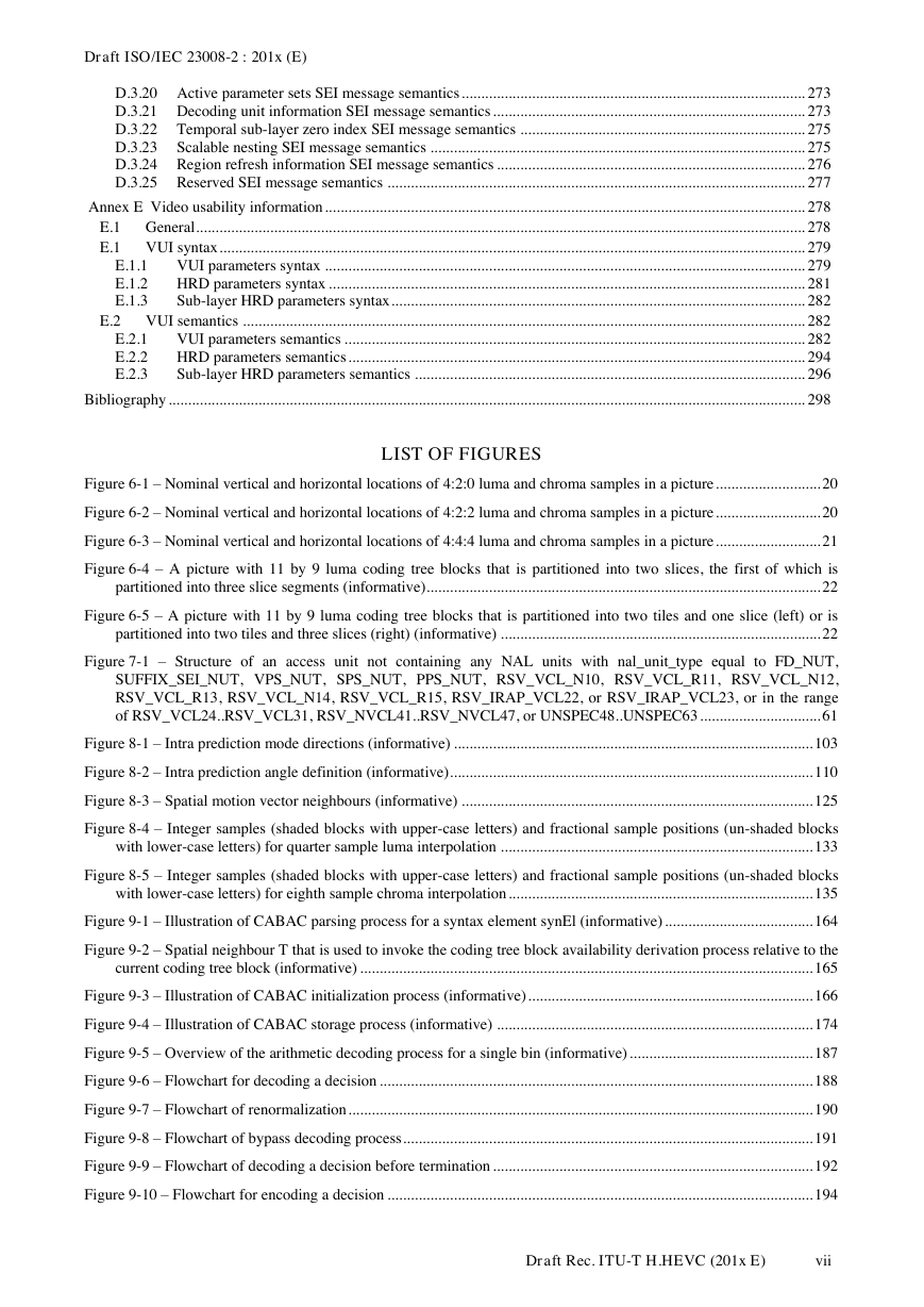
LIST OF FIGURES
Figure 6-1 – Nominal vertical and horizontal locations of 4:2:0 luma and chroma samples in a picture ........................... 20
Figure 6-2 – Nominal vertical and horizontal locations of 4:2:2 luma and chroma samples in a picture ........................... 20
Figure 6-3 – Nominal vertical and horizontal locations of 4:4:4 luma and chroma samples in a picture ........................... 21
Figure 6-4 – A picture with 11 by 9 luma coding tree blocks that is partitioned into two slices, the first of which is
partitioned into three slice segments (informative) ..................................................................................................... 22
Figure 6-5 – A picture with 11 by 9 luma coding tree blocks that is partitioned into two tiles and one slice (left) or is
partitioned into two tiles and three slices (right) (informative) .................................................................................. 22
Figure 7-1 – Structure of an access unit not containing any NAL units with nal_unit_type equal to FD_NUT,
SUFFIX_SEI_NUT, VPS_NUT, SPS_NUT, PPS_NUT, RSV_VCL_N10, RSV_VCL_R11, RSV_VCL_N12,
RSV_VCL_R13, RSV_VCL_N14, RSV_VCL_R15, RSV_IRAP_VCL22, or RSV_IRAP_VCL23, or in the range
of RSV_VCL24..RSV_VCL31, RSV_NVCL41..RSV_NVCL47, or UNSPEC48..UNSPEC63 ............................... 61
Figure 8-1 – Intra prediction mode directions (informative) ............................................................................................ 103
Figure 8-2 – Intra prediction angle definition (informative) ............................................................................................. 110
Figure 8-3 – Spatial motion vector neighbours (informative) .......................................................................................... 125
Figure 8-4 – Integer samples (shaded blocks with upper-case letters) and fractional sample positions (un-shaded blocks
with lower-case letters) for quarter sample luma interpolation ................................................................................ 133
Figure 8-5 – Integer samples (shaded blocks with upper-case letters) and fractional sample positions (un-shaded blocks
with lower-case letters) for eighth sample chroma interpolation .............................................................................. 135
Figure 9-1 – Illustration of CABAC parsing process for a syntax element synEl (informative) ...................................... 164
Figure 9-2 – Spatial neighbour T that is used to invoke the coding tree block availability derivation process relative to the
current coding tree block (informative) .................................................................................................................... 165
Figure 9-3 – Illustration of CABAC initialization process (informative) ......................................................................... 166
Figure 9-4 – Illustration of CABAC storage process (informative) ................................................................................. 174
Figure 9-5 – Overview of the arithmetic decoding process for a single bin (informative) ............................................... 187
Figure 9-6 – Flowchart for decoding a decision ............................................................................................................... 188
Figure 9-7 – Flowchart of renormalization ....................................................................................................................... 190
Figure 9-8 – Flowchart of bypass decoding process ......................................................................................................... 191
Figure 9-9 – Flowchart of decoding a decision before termination .................................................................................. 192
Figure 9-10 – Flowchart for encoding a decision ............................................................................................................. 194
Draft Rec. ITU-T H.HEVC (201x E)
vii
�
Draft ISO/IEC 23008-2 : 201x (E)
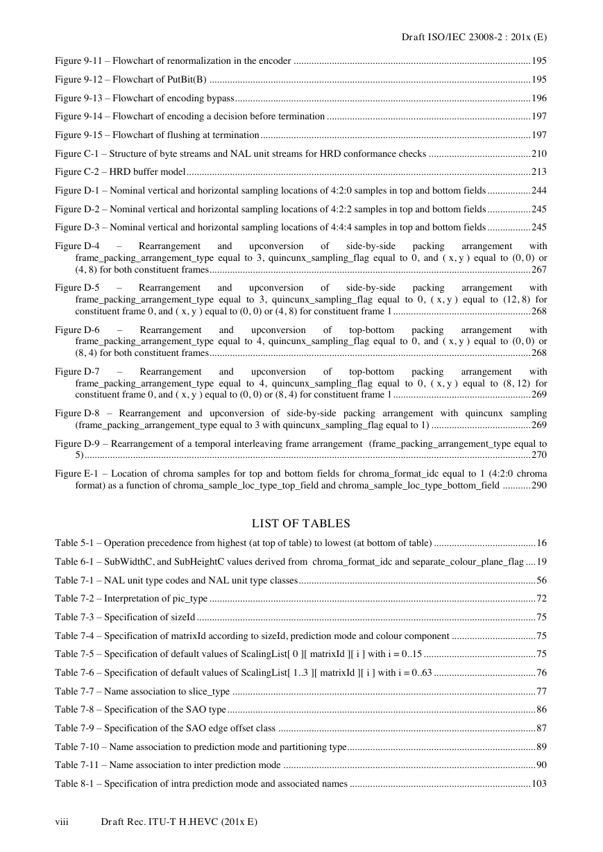
Figure 9-11 – Flowchart of renormalization in the encoder ............................................................................................. 195
Figure 9-12 – Flowchart of PutBit(B) .............................................................................................................................. 195
Figure 9-13 – Flowchart of encoding bypass .................................................................................................................... 196
Figure 9-14 – Flowchart of encoding a decision before termination ................................................................................ 197
Figure 9-15 – Flowchart of flushing at termination .......................................................................................................... 197
Figure C-1 – Structure of byte streams and NAL unit streams for HRD conformance checks ........................................ 210
Figure C-2 – HRD buffer model ....................................................................................................................................... 213
Figure D-1 – Nominal vertical and horizontal sampling locations of 4:2:0 samples in top and bottom fields ................. 244
Figure D-2 – Nominal vertical and horizontal sampling locations of 4:2:2 samples in top and bottom fields ................. 245
Figure D-3 – Nominal vertical and horizontal sampling locations of 4:4:4 samples in top and bottom fields ................. 245
Figure D-4
–
Rearrangement
arrangement with
frame_packing_arrangement_type equal to 3, quincunx_sampling_flag equal to 0, and ( x, y ) equal to (0, 0) or
(4, 8) for both constituent frames .............................................................................................................................. 267
upconversion
side-by-side
packing
and
of
Figure D-5
–
Rearrangement
arrangement with
frame_packing_arrangement_type equal to 3, quincunx_sampling_flag equal to 0, ( x, y ) equal to (12, 8) for
constituent frame 0, and ( x, y ) equal to (0, 0) or (4, 8) for constituent frame 1 ...................................................... 268
upconversion
side-by-side
packing
and
of
Figure D-6
–
Rearrangement
with
frame_packing_arrangement_type equal to 4, quincunx_sampling_flag equal to 0, and ( x, y ) equal to (0, 0) or
(8, 4) for both constituent frames .............................................................................................................................. 268
upconversion
arrangement
top-bottom
packing
and
of
Figure D-7
–
Rearrangement
with
frame_packing_arrangement_type equal to 4, quincunx_sampling_flag equal to 0, ( x, y ) equal to (8, 12) for
constituent frame 0, and ( x, y ) equal to (0, 0) or (8, 4) for constituent frame 1 ...................................................... 269
upconversion
arrangement
top-bottom
packing
and
of
Figure D-8 – Rearrangement and upconversion of side-by-side packing arrangement with quincunx sampling
(frame_packing_arrangement_type equal to 3 with quincunx_sampling_flag equal to 1) ....................................... 269
Figure D-9 – Rearrangement of a temporal interleaving frame arrangement (frame_packing_arrangement_type equal to
5) ............................................................................................................................................................................... 270
Figure E-1 – Location of chroma samples for top and bottom fields for chroma_format_idc equal to 1 (4:2:0 chroma
format) as a function of chroma_sample_loc_type_top_field and chroma_sample_loc_type_bottom_field ........... 290
LIST OF TABLES
Table 5-1 – Operation precedence from highest (at top of table) to lowest (at bottom of table) ........................................ 16
Table 6-1 – SubWidthC, and SubHeightC values derived from chroma_format_idc and separate_colour_plane_flag .... 19
Table 7-1 – NAL unit type codes and NAL unit type classes ............................................................................................. 56
Table 7-2 – Interpretation of pic_type ................................................................................................................................ 72
Table 7-3 – Specification of sizeId ..................................................................................................................................... 75
Table 7-4 – Specification of matrixId according to sizeId, prediction mode and colour component ................................. 75
Table 7-5 – Specification of default values of ScalingList[ 0 ][ matrixId ][ i ] with i = 0..15 ............................................ 75
Table 7-6 – Specification of default values of ScalingList[ 1..3 ][ matrixId ][ i ] with i = 0..63 ........................................ 76
Table 7-7 – Name association to slice_type ....................................................................................................................... 77
Table 7-8 – Specification of the SAO type ......................................................................................................................... 86
Table 7-9 – Specification of the SAO edge offset class ..................................................................................................... 87
Table 7-10 – Name association to prediction mode and partitioning type.......................................................................... 89
Table 7-11 – Name association to inter prediction mode ................................................................................................... 90
Table 8-1 – Specification of intra prediction mode and associated names ....................................................................... 103
viii
Draft Rec. ITU-T H.HEVC (201x E)
�



 2023年江西萍乡中考道德与法治真题及答案.doc
 2012年重庆南川中考生物真题及答案.doc
 2013年江西师范大学地理学综合及文艺理论基础考研真题.doc
 2020年四川甘孜小升初语文真题及答案I卷.doc
 2020年注册岩土工程师专业基础考试真题及答案.doc
 2023-2024学年福建省厦门市九年级上学期数学月考试题及答案.doc
 2021-2022学年辽宁省沈阳市大东区九年级上学期语文期末试题及答案.doc
 2022-2023学年北京东城区初三第一学期物理期末试卷及答案.doc
 2018上半年江西教师资格初中地理学科知识与教学能力真题及答案.doc
 2012年河北国家公务员申论考试真题及答案-省级.doc
 2020-2021学年江苏省扬州市江都区邵樊片九年级上学期数学第一次质量检测试题及答案.doc
 2022下半年黑龙江教师资格证中学综合素质真题及答案.doc