WHITE PAPER
Hybrid Beamforming for Massive MIMO
Phased Array Systems
�
Introduction
This paper demonstrates how you can use MATLAB® and Simulink® features and toolboxes to:
1. Design and synthesize complex antenna elements and MIMO phased arrays and subarrays
2. Partition hybrid beamforming systems intelligently across RF and digital domains
3. Validate spatial signal processing algorithm concepts
4. Verify link-level designs using high-fidelity simulations
5. Evaluate the impacts of failed or imperfect elements and subarrays
6. Eliminate design problems before building hardware
A fundamental goal of MATLAB and Simulink products for this application is to provide a direct
path to expand the level of fidelity of the model over the many phases of project development. This
includes tasks such as bringing measured data into the model for the antenna pattern and the propa-
gation paths. It also includes expanding the level of fidelity of the RF chain by bringing in models of
RF components in the context of multidomain simulation with Simulink.
Note: In the examples below, we use Phased Array System Toolbox™, Antenna Toolbox™, RF Blockset,
RF Toolbox™, Communications System Toolbox™, and Global Optimization Toolbox to complete the
associated workflows.
Challenges Designing Massive MIMO Arrays for 5G
As 5G standards continue to evolve, the goals for higher data rates, lower latency network access, and
more energy efficient implementations are clear. Higher data rates drive the need for greater band-
width systems. The available bandwidth in the spectrum up through 6 GHz is not sufficient to satisfy
these requirements. This has moved the target operating frequency bands up into the millimeter wave
range for the next generation of wireless communication systems.
Intelligent Array Design with Beamforming
Smaller wavelengths at these higher frequency bands enable implementations with more antenna ele-
ments per system within small form factors. Signal path and propagation challenges associated with
operating at these frequencies also increases. For example, the attenuation due to gas absorption for a
60-GHz waveform is more than 10 dB/km, while a 700-MHz waveform experiences an attenuation on
the order of 0.01 dB/km. You can offset these losses with intelligent array design and the use of spatial
signal processing techniques, including beamforming. This type of processing is enabled by massive
MIMO arrays and can be used directly to provide higher link-level gains to overcome path loss and
undesirable interference sources.
To achieve the most control and flexibility with beamforming in an active array design, it is desirable
to have independent weighting control over each antenna array element. This requires a transmit/
W H I T E PA P E R | 2
Hybrid Beamforming for Massive MIMO Phased Array Systems�
receive (T/R) module dedicated to each element. For array sizes that are typical of a massive MIMO
communication system, this type of architecture is difficult to build due to cost, space, and power
limitations. For example, having a high performance ADC and DAC for every channel (along with
the supporting components) can drive the cost and power beyond allocated design budgets. Similarly,
having variable gain amplifiers in the RF chain for each channel increases the system cost.
Hybrid Beamforming
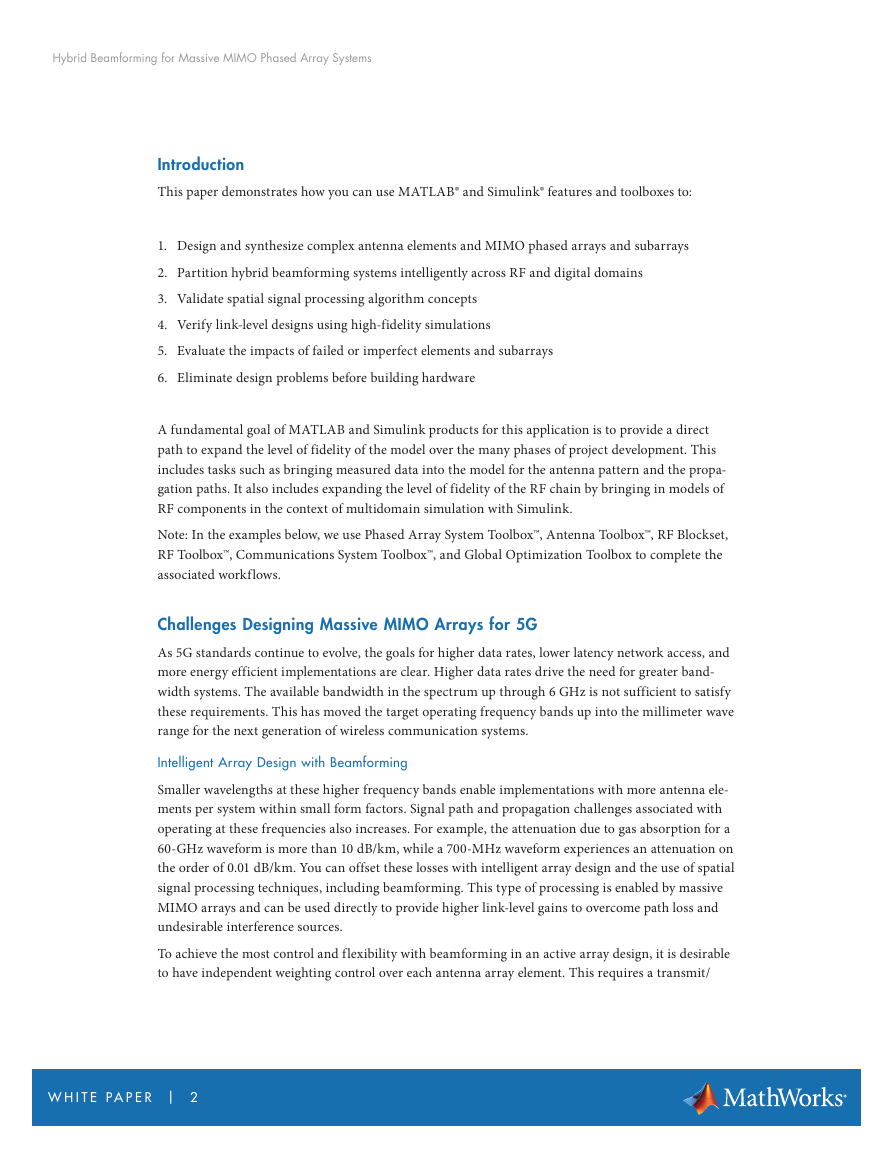
Hybrid beamforming is a technique you can use to partition beamforming between the digital and
RF domains. System designers can implement hybrid beamforming to balance flexibility and cost
trade-offs while still fielding a system that meets the required performance parameters. Hybrid
beamforming designs are developed by combining multiple array elements into subarray modules. A
transmit/receive (T/R) module is dedicated to a subarray in the array and therefore fewer T/R mod-
ules are required in the system. The number of elements, and the positioning within each subarray,
can be selected to ensure system-level performance is met across a range of steering angles.
Using the transmit signal chain as our first example, each element within a subarray can have a phase
shift applied directly in the RF domain, while digital beamforming techniques based on complex
weighting vectors can be applied on the signals that feed each subarray. Digital beamforming allows
control of the signal for both amplitude and phase on signals aggregated at the subarray level. For cost
and complexity reasons, the RF control is typically limited to applying phase shifts to each
of the elements.
Figure 1. Hybrid beamforming architecture.
Systems such as the one shown in Figure 1 are complex to develop. You can use modeling techniques
to design and evaluate massive MIMO arrays and the corresponding RF and digital architectures
needed to help manage their complexity. With these techniques, you can reduce risk and validate
design approaches at the earliest stages of a project. We will first look at an array design example.
We have selected parameters for each of the examples that are common in the 5G wireless community
but all of the examples shown can be modified to match your desired configuration.
W H I T E PA P E R | 3
Hybrid Beamforming for Massive MIMO Phased Array Systems�
Designing the Array
There are many factors to consider when designing an array. Typical array designs include parameters
such as array geometry, element spacing, the lattice structure of the elements, and element tapering.
In addition, the effects of mutual coupling are important to characterize before the final design is
implemented. Once an initial configuration of the array design is complete, architectural partitioning
can be iteratively evaluated against the overall system performance goals.
With millimeter wave systems, the area of the array is reduced in proportion to the wavelength size.
As an example, an antenna array designed at millimeter wave frequencies can be up to 100 times
smaller than an array designed to operate at microwave frequencies. By building an array with a
larger number of antenna elements, you can achieve a high beamforming gain. The highly directive
beam helps to offset the increased path loss at higher frequencies of operations, as beams are steered
to a specific direction.
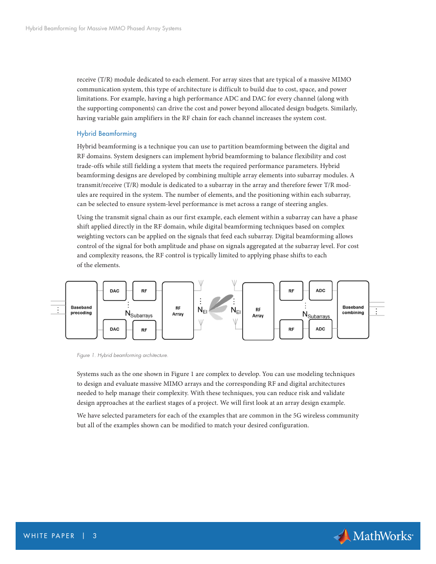
To start the array design process, the Sensor Array Analyzer app, which is available with Phased
Array System Toolbox, can be launched from the MATLAB prompt:
>> sensorArrayAnalyzer
Figure 2. Sensor Array Analyzer app for Array Design.
W H I T E PA P E R | 4
Hybrid Beamforming for Massive MIMO Phased Array Systems�
You can edit all design parameters that define an array directly on the left side of the app in the Array
Settings window shown in Figure 2. The parameters include array size, array geometry, element spac-
ing, and tapering.
From the app, you can easily visualize the resulting geometry, 2D and 3D Directivity, and the Grating
Lobe Diagrams.
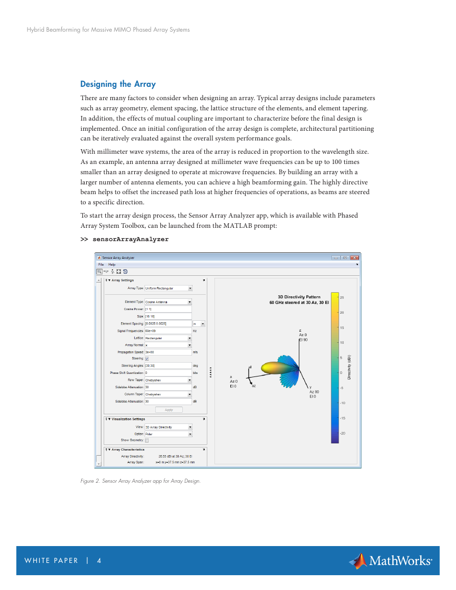
To achieve steering in azimuth and elevation, you can design a uniformly spaced planar array. Figure
3 shows an example of a 64x64 uniform rectangular array that was designed within the Sensor Array
Analyzer app. The large number of elements provides a high level of directivity. The design shown
below also has tapering applied to the rows and columns of the array to reduce sidelobe levels. As is
the case with all design choices, the larger antenna gains achieved with narrower beams must be bal-
anced with the fact that MIMO systems are based on scattering environments that also depend on
broader beam patterns to maximize channel capacity. This trade-off can also be assessed during the
interactive design process.
Figure 3. Beam pattern and grating lobe diagram for 66 GHz 64x64 element design.
The image displayed in the right side of Figure 3 shows that with half wavelength spacing between the
elements, there are no grating lobes present across the full range of steering directions as expected. It
is important to understand the impacts here because it may be necessary to increase the spacing
between the elements to mitigate the effects of mutual coupling. This is an important design consid-
eration that needs to be accounted for. Fortunately, at higher frequencies where half wavelength spac-
ing is small to start with, an increase in element separation by 10% of a wavelength only requires a
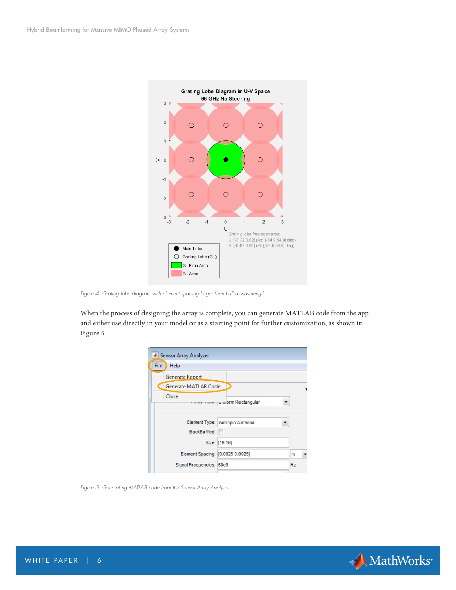
change of less than 0.5 mm at 66 GHz. Figure 4 shows the trade-off that must be considered using a
grating lobe diagram with a 10% increase in the spacing between the elements. For this example, grat-
ing lobes are only present with azimuth and elevation angles outside +/- 54.9 degrees. This can be
traded off against the array with less space between elements (and more mutual coupling effects).
W H I T E PA P E R | 5
Hybrid Beamforming for Massive MIMO Phased Array Systems�
Figure 4. Grating lobe diagram with element spacing larger than half a wavelength
When the process of designing the array is complete, you can generate MATLAB code from the app
and either use directly in your model or as a starting point for further customization, as shown in
Figure 5.
Figure 5. Generating MATLAB code from the Sensor Array Analyzer.
W H I T E PA P E R | 6
Hybrid Beamforming for Massive MIMO Phased Array Systems�
Extending the Model Fidelity: Antenna and RF
In the previous example, an ideal antenna element was used to model the array pattern. There are
multiple ideal elements choices available to get started with, including an omnidirectional and a
cosine element. The element being used in the next example is no longer ideal and is based on a patch
antenna designed for 66 GHz resonance. The full MATLAB example for this type of antenna element
design is located here.
We have extracted some of the key code sections to show how an antenna can be quickly designed in
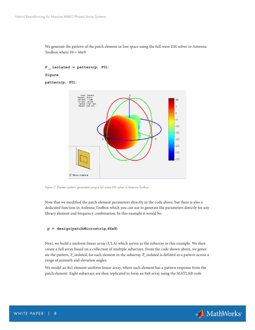
Antenna Toolbox. We use a patch micro-strip element that resonates at 66GHz in our example. The
resulting pattern is also shown below in Figure 7.
We start with a patch element in the Antenna Toolbox library and directly modify the patch parame-
ters to operate at 66GHz. The code sample and patch structure (shown in Figure 6) are shown below.
p = patchMicrostrip;
p.Length = 0.49*lambda;
p.Width = 1.5*0.49*lambda;
p.Height = 0.01*lambda;
p.GroundPlaneLength = lambda;
p.GroundPlaneWidth = lambda;
Figure 6. Patch Microstrip Element.
W H I T E PA P E R | 7
Hybrid Beamforming for Massive MIMO Phased Array Systems�
We generate the pattern of the patch element in free space using the full wave EM solver in Antenna
Toolbox where F0 = 66e9:
P _ isolated = pattern(p, F0);
figure
pattern(p, F0);
Figure 7. Element pattern generated using a full wave EM solver in Antenna Toolbox.
Note that we modified the patch element parameters directly in the code above, but there is also a
dedicated function in Antenna Toolbox which you can use to generate the parameters directly for any
library element and frequency combination. In this example it would be:
p = design(patchMicrostrip,66e9)
Next, we build a uniform linear array (ULA) which serves as the subarray in this example. We then
create a full array based on a collection of multiple subarrays. From the code shown above, we gener-
ate the pattern, P_isolated, for each element in the subarray. P_isolated is defined as a pattern across a
range of azimuth and elevation angles.
We model an 8x1 element uniform linear array, where each element has a pattern response from the
patch element. Eight subarrays are then replicated to form an 8x8 array using the MATLAB code
W H I T E PA P E R | 8
Hybrid Beamforming for Massive MIMO Phased Array Systems�




 2023年江西萍乡中考道德与法治真题及答案.doc
 2012年重庆南川中考生物真题及答案.doc
 2013年江西师范大学地理学综合及文艺理论基础考研真题.doc
 2020年四川甘孜小升初语文真题及答案I卷.doc
 2020年注册岩土工程师专业基础考试真题及答案.doc
 2023-2024学年福建省厦门市九年级上学期数学月考试题及答案.doc
 2021-2022学年辽宁省沈阳市大东区九年级上学期语文期末试题及答案.doc
 2022-2023学年北京东城区初三第一学期物理期末试卷及答案.doc
 2018上半年江西教师资格初中地理学科知识与教学能力真题及答案.doc
 2012年河北国家公务员申论考试真题及答案-省级.doc
 2020-2021学年江苏省扬州市江都区邵樊片九年级上学期数学第一次质量检测试题及答案.doc
 2022下半年黑龙江教师资格证中学综合素质真题及答案.doc