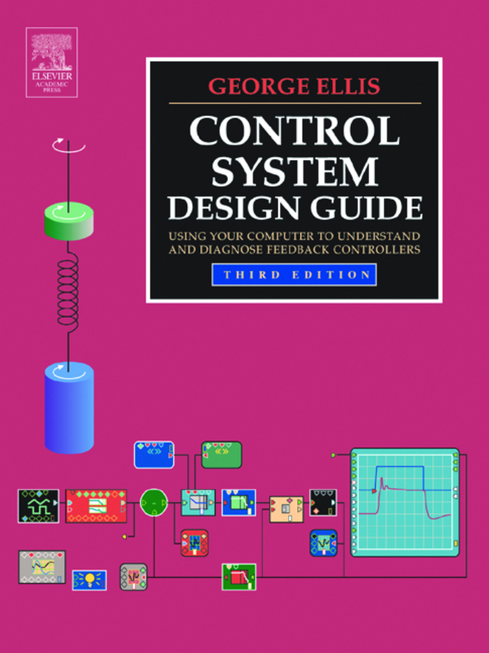
Cover
Frontmatter
Half Title Page
Title Page
Copyright
Dedication Page
Contents
Preface
Section I: Applied Principles of Controls
Important Safety Guidelines for Readers
1. Introduction to Controls
1.1 Visual ModelQ Simulation Environment
1.2 The Control System
1.3 The Controls Engineer
2. The Frequency Domain
2.1 The Laplace Transform
2.2 Transfer Functions
2.3 Examples of Transfer Functions
2.4 Block Diagrams
2.5 Phase and Gain
2.6 Measuring Performance
2.7 Questions
3. Tuning a Control System
3.1 Closing Loops
3.2 A Detailed Review of the Model
3.3 The Open-Loop Method
3.4 Margins of Stability
3.5 A Zone-Based Tuning Procedure
3.6 Variation in Plant Gain
3.7 Multiple (Cascaded) Loops
3.8 Saturation and Synchronization
3.9 Questions
4. Delay in Digital Controllers
4.1 How Sampling Works
4.2 Sources of Delay in Digital Systems
4.3 Experiment 4A: Understanding Delay in Digital Control
4.4 Selecting the Sample Time
4.5 Questions
5. The z-Domain
5.1 Introduction to the z-Domain
5.2 z Phasors
5.3 Aliasing
5.4 Experiment 5A: Aliasing
5.5 From Transfer Function to Algorithm
5.6 Functions for Digital Systems
5.7 Reducing the Calculation Delay
5.8 Selecting a Processor
5.9 Quantization
5.10 Questions
6. Six Types of Controllers
6.1 Tuning in This Chapter
6.2 Using the Proportional Gain
6.3 Using the Integral Gain
6.4 Using the Differential Gain
6.5 PID+ Control
6.6 PD Control
6.7 Choosing the Controller
6.8 Experiments 6A–6F
6.9 Questions
7. Disturbance Response
7.1 Disturbances
7.2 Disturbance Response of a Velocity Controller
7.3 Disturbance Decoupling
7.4 Questions
8. Feed-Forward
8.1 Plant-Based Feed-Forward
8.2 Feed-Forward and the Power Converter
8.3 Delaying the Command Signal
8.4 Variation in Plant and Power Converter Operation
8.5 Feed-Forward for the Double-Integrating Plant
8.6 Questions
9. Filters in Control Systems
9.1 Filters in Control Systems
9.2 Filter Passband
9.3 Implementation of Filters
9.4 Questions
10. Introduction to Observers in Control Systems
10.1 Overview of Observers
10.2 Experiments 10A–10C: Enhancing Stability with an Observer
10.3 Filter Form of the Luenberger Observer
10.4 Designing a Luenberger Observer
10.5 Introduction to Tuning an Observer Compensator
10.6 Questions
Section II: Modeling
11. Introduction to Modeling
11.1 What Is a Model?
11.2 Frequency-Domain Modeling
11.3 Time-Domain Modeling
11.4 Questions
12. Nonlinear Behavior and Time Variation
12.1 LTI Versus non-LTI
12.2 Non-LTI Behavior
12.3 Dealing with Nonlinear Behavior
12.4 Ten Examples of Nonlinear Behavior
12.5 Questions
13. Seven Steps to Developing a Model
13.1 Determine the Purpose of the Model
13.2 Model in SI Units
13.3 Identify the System
13.4 Build the Block Diagram
13.5 Select Frequency or Time Domain
13.6 Write the Model Equations
13.7 Verify the Model
Section III: Motion Control
14. Encoders and Resolvers
14.1 Accuracy, Resolution, and Response
14.2 Encoders
14.3 Resolvers
14.4 Position Resolution, Velocity Estimation, and Noise
14.5 Alternatives for Increasing Resolution
14.6 Cyclic Error and Torque/Velocity Ripple
14.7 Experiment 14B: Cyclical Errors and Torque Ripple
14.8 Choosing a Feedback Device
14.9 Questions
15. Basics of the Electric Servomotor and Drive
15.1 Definition of a Drive
15.2 Definition of a Servo System
15.3 Basic Magnetics
15.4 Electric Servomotors
15.5 Permanent-Magnet (PM) Brush Motors
15.6 Brushless PM Motors
15.7 Six-Step Control of Brushless PM Motor
15.8 Induction and Reluctance Motors
15.9 Questions
16. Compliance and Resonance
16.1 Equations of Resonance
16.2 Tuned Resonance vs. Inertial-Reduction Instability
16.3 Curing Resonance
16.4 Questions
17. Position-Control Loops
17.1 P/PI Position Control
17.2 PI/P Position Control
17.3 PID Position Control
17.4 Comparison of Position Loops
17.5 Bode Plots for Positioning Systems
17.6 Questions
18. Using the Luenberger Observer in Motion Control
18.1 Applications Likely to Benefit from Observers
18.2 Observing Velocity to Reduce Phase Lag
18.3 Acceleration Feedback
18.4 Questions
Appendix A: Active Analog Implementation of Controller Elements
Integrator
Differentiator
Lag Compensator
Lead Compensator
Lead-Lag Compensator
Sallen-and-Key Low-Pass Filter
Adjustable Notch Filter
Appendix B: European Symbols for Block Diagrams
Part I. Linear Functions
Part II. Nonlinear Functions
Appendix C: The Runge–Kutta Method
The Runge–Kutta Algorithm
Basic Version of the Runge–Kutta Algorithm
C Programming Language Version of the Runge–Kutta Algorithm
H-File for C Programming Language Version
Appendix D: Development of the Bilinear Transformation
Bilinear Transformation
Prewarping
Factoring Polynomials
Phase Advancing
Appendix E: The Parallel Form of Digital Algorithms
Appendix F: Basic Matrix Math
Matrix Summation
Matrix Multiplication
Matrix Scaling
Matrix Inversion
Appendix G: Answers to End–of–Chapter Questions
Chapter 2
Chapter 3
Chapter 4
Chapter 5
Chapter 6
Chapter 7
Chapter 8
Chapter 9
Chapter 10
Chapter 11
Chapter 12
Chapter 14
Chapter 15
Chapter 16
Chapter 17
Chapter 18
References
Index


 2023年江西萍乡中考道德与法治真题及答案.doc
 2012年重庆南川中考生物真题及答案.doc
 2013年江西师范大学地理学综合及文艺理论基础考研真题.doc
 2020年四川甘孜小升初语文真题及答案I卷.doc
 2020年注册岩土工程师专业基础考试真题及答案.doc
 2023-2024学年福建省厦门市九年级上学期数学月考试题及答案.doc
 2021-2022学年辽宁省沈阳市大东区九年级上学期语文期末试题及答案.doc
 2022-2023学年北京东城区初三第一学期物理期末试卷及答案.doc
 2018上半年江西教师资格初中地理学科知识与教学能力真题及答案.doc
 2012年河北国家公务员申论考试真题及答案-省级.doc
 2020-2021学年江苏省扬州市江都区邵樊片九年级上学期数学第一次质量检测试题及答案.doc
 2022下半年黑龙江教师资格证中学综合素质真题及答案.doc