K8T800 Pro
D O U
81900427C
�
@ v
U
UT@vO@Ag\iNB
eC
UwTAUP~bSwA
AsybLFALOt
FIC~A~WPU
etqF~syOHvQABL
DqHqC
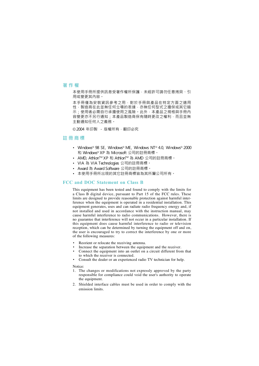
© 2004 ~Ls
- vALs
• Windows® 98 SE, Windows ® ME, Windows NT ® 4.0, Windows ® 2000
M Windows ® XP
Microsoft qUC
• AMD, Athlon TM XP M AthlonTM
• VIA
VIA Technologies qUC
• Award
Award Software qUC
• UX{UqC
AMD qUC
FCC and DOC Statement on Class B
This equipment has been tested and found to comply with the limits for
a Class B digital device, pursuant to Part 15 of the FCC rules. These
limits are designed to provide reasonable protection against harmful inter-
ference when the equipment is operated in a residential installation. This
equipment generates, uses and can radiate radio frequency energy and, if
not installed and used in accordance with the instruction manual, may
cause harmful interference to radio communications. However, there is
no guarantee that interference will not occur in a particular installation. If
this equipment does cause harmful interference to radio or television
reception, which can be determined by turning the equipment off and on,
the user is encouraged to try to correct the interference by one or more
of the following measures:
• Reorient or relocate the receiving antenna.
•
• Connect the equipment into an outlet on a circuit different from that
Increase the separation between the equipment and the receiver.
to which the receiver is connected.
• Consult the dealer or an experienced radio TV technician for help.
Notice:
1. The changes or modifications not expressly approved by the party
responsible for compliance could void the user's authority to operate
the equipment.
2. Shielded interface cables must be used in order to comply with the
emission limits.
�
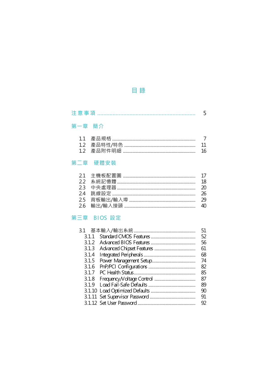
................................................................
5
` N
@
1.1
1.2
1.2
~W
~S
~
.....................................................................
...........................................................
/ S
............................................................
G
ww
2.1 DOtm
2.2
tO
2.3 Bz
2.4
u]w
2.5
IOX
2.6 X / JY
............................................................
.................................................................
.................................................................
.....................................................................
.......................................................
/ J
...........................................................
T
B I O S ]w
3.1
/ Xt
...................................................
J
3.1.1
Standard CMOS Features .....................................
3.1.2 Advanced BIOS Features .....................................
3.1.3 Advanced Chipset Features ..................................
Integrated Peripherals ...........................................
3.1.4
Power Management Setup ....................................
3.1.5
3.1.6
PnP/PCI Configurations .......................................
PC Health Status ...................................................
3.1.7
3.1.8
Frequency/Voltage Control ..................................
3.1.9 Load Fail-Safe Defaults .......................................
3.1.10 Load Optimized Defaults .....................................
3.1.11 Set Supervisor Password ......................................
3.1.12 Set User Password ................................................
7
11
16
17
18
20
26
29
40
51
52
56
61
68
74
82
85
87
89
90
91
92
�
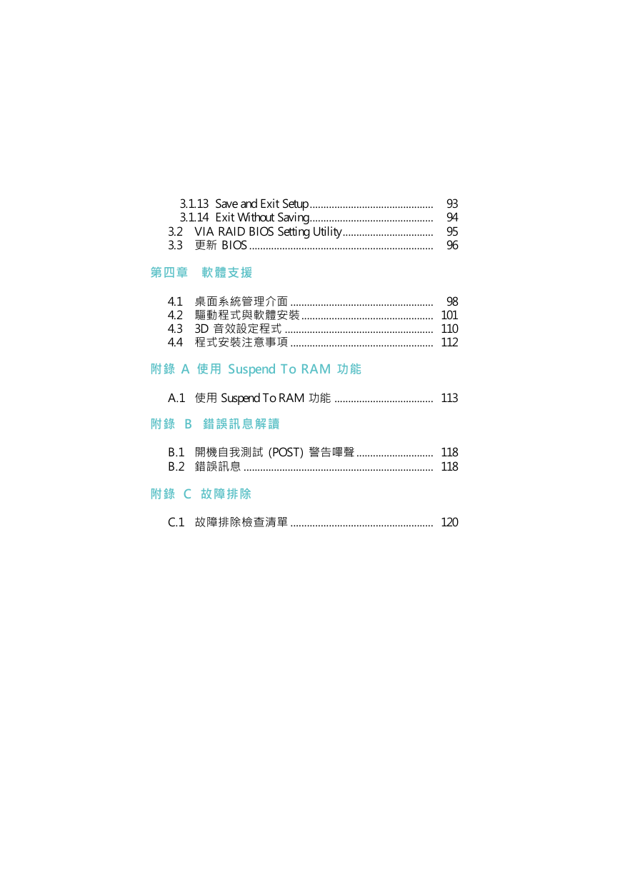
3.1.13 Save and Exit Setup .............................................
3.1.14 Exit Without Saving .............................................
3.2 VIA RAID BIOS Setting Utility .................................
3.3
BIOS ...................................................................
s
93
94
95
96
|
n
tz
4.1
4.2 X{Pnw
3D ]w{
4.3
4.4
{w`N
....................................................
98
................................................ 101
...................................................... 110
.................................................... 112
A
S u s p e n d T o R A M \
A.1
Suspend To RAM \
.................................... 113
B ~T
B.1 }
B.2 ~T
C G
(POST) in
............................ 118
..................................................................... 118
C.1 GdM
.................................................... 120
�
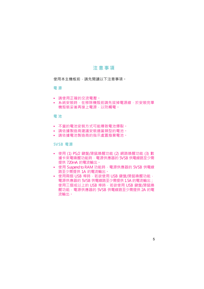
` N
DOeA\HU`NC
q
• TyqC
• twAbequAw
AWqAHqC
q
• qwiPqzC
• sywAqC
• qsyBmoqC
5 V S B q
•
•
•
720mA qyX
C
Suspend to RAM \Aq
1A qyX
USB AY
5VSB qu
C
USB L
(1) PS/2 L
/\
dq\Aq
(2) \
5VSB qu
(3)
q
THW
\Aq
yX
C
USB AY
5VSB qu
5VSB qu
/\A
1.5A qyXF
USB L
/
2A q
5
�
X {
C@X{wAs}CY{
w~s}Ai|DC
/ \
iDHU
\
DOW\iHU@G
Gigabit A
•
LAN Phy -
•
/\G
-
10/100/1000 Mbps v
10/100 Mbps v
IEEE 1394 \
•
VIA VT6307 ADOIOm
DOW
IEEE 1394 YC
YHWAUC
IEEE 1394 P
�
@
-
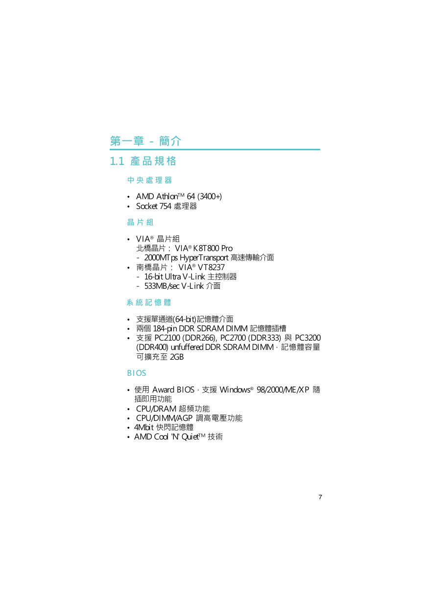
1.1 ~ W
B z
• AMD Athlon TM 64 (3400+)
• Socket 754 Bz
• VIA®
VIA® K8T800 Pro
_G
- 2000MTps HyperTransport t
• n
G VIA ® VT8237
- 16-bit Ultra V-Link D
- 533MB/sec V-Link
t O
• qD
•
•
(64-bit)O
184-pin DDR SDRAM DIMM O
PC2100 (DDR266), PC2700 (DDR333) P PC3200
(DDR400) unfuffered DDR SDRAM DIMMAOeq
iXR
2GB
B I O S
•
Y\
Award BIOS A
Windows 98/2000/ME/XP H
• CPU/DRAM WW\
• CPU/DIMM/AGP q\
• 4Mbit {O
• AMD Cool 'N' QuietTM N
7
�
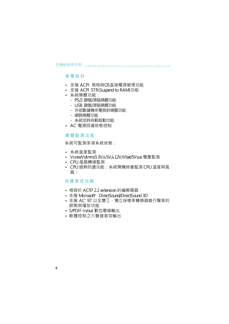
DOU
q ] p
•
•
• t\G
ACPI WP
ACPI STR(Suspend to RAM) \
OSqz\
/\
/\
- PS/2 L
- USB L
- ~qa\
-
-
\
tw\
• AC q^_A
w \
tihtAG
• t
• Vcore/Vdimm/3.3V/– 5V/– 12V/Vbat/5Vsus q
• CPU
• CPU L\Gt}|
t
CPU P
C
\
• e
•
•
sP\
AC97 2.2 extension sX
Microsoft® DirectSound/DirectSound 3D
AC’97 HuBWvin
• S/PDIF-in/out YX
• nnDX
8
�




 2023年江西萍乡中考道德与法治真题及答案.doc
 2012年重庆南川中考生物真题及答案.doc
 2013年江西师范大学地理学综合及文艺理论基础考研真题.doc
 2020年四川甘孜小升初语文真题及答案I卷.doc
 2020年注册岩土工程师专业基础考试真题及答案.doc
 2023-2024学年福建省厦门市九年级上学期数学月考试题及答案.doc
 2021-2022学年辽宁省沈阳市大东区九年级上学期语文期末试题及答案.doc
 2022-2023学年北京东城区初三第一学期物理期末试卷及答案.doc
 2018上半年江西教师资格初中地理学科知识与教学能力真题及答案.doc
 2012年河北国家公务员申论考试真题及答案-省级.doc
 2020-2021学年江苏省扬州市江都区邵樊片九年级上学期数学第一次质量检测试题及答案.doc
 2022下半年黑龙江教师资格证中学综合素质真题及答案.doc