SECTION THREE: IEEE Std 802.3-2005
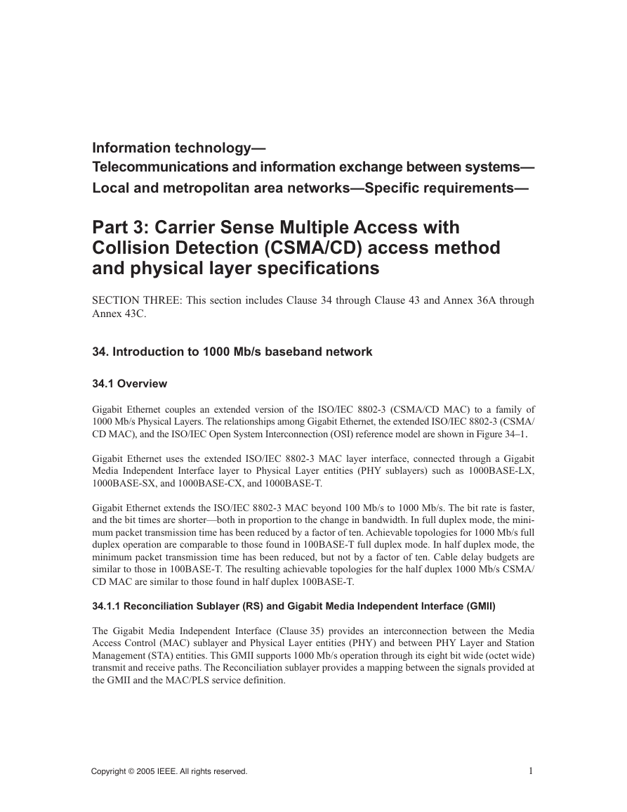
34. Introduction to 1000 Mb/s baseband network
34.1 Overview
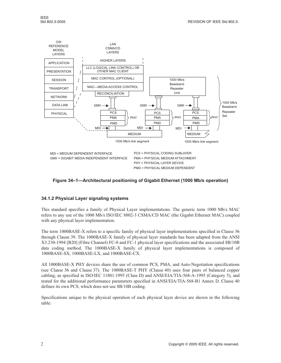
34.1.1 Reconciliation Sublayer (RS) and Gigabit Media Independent Interface (GMII)
34.1.2 Physical Layer signaling systems
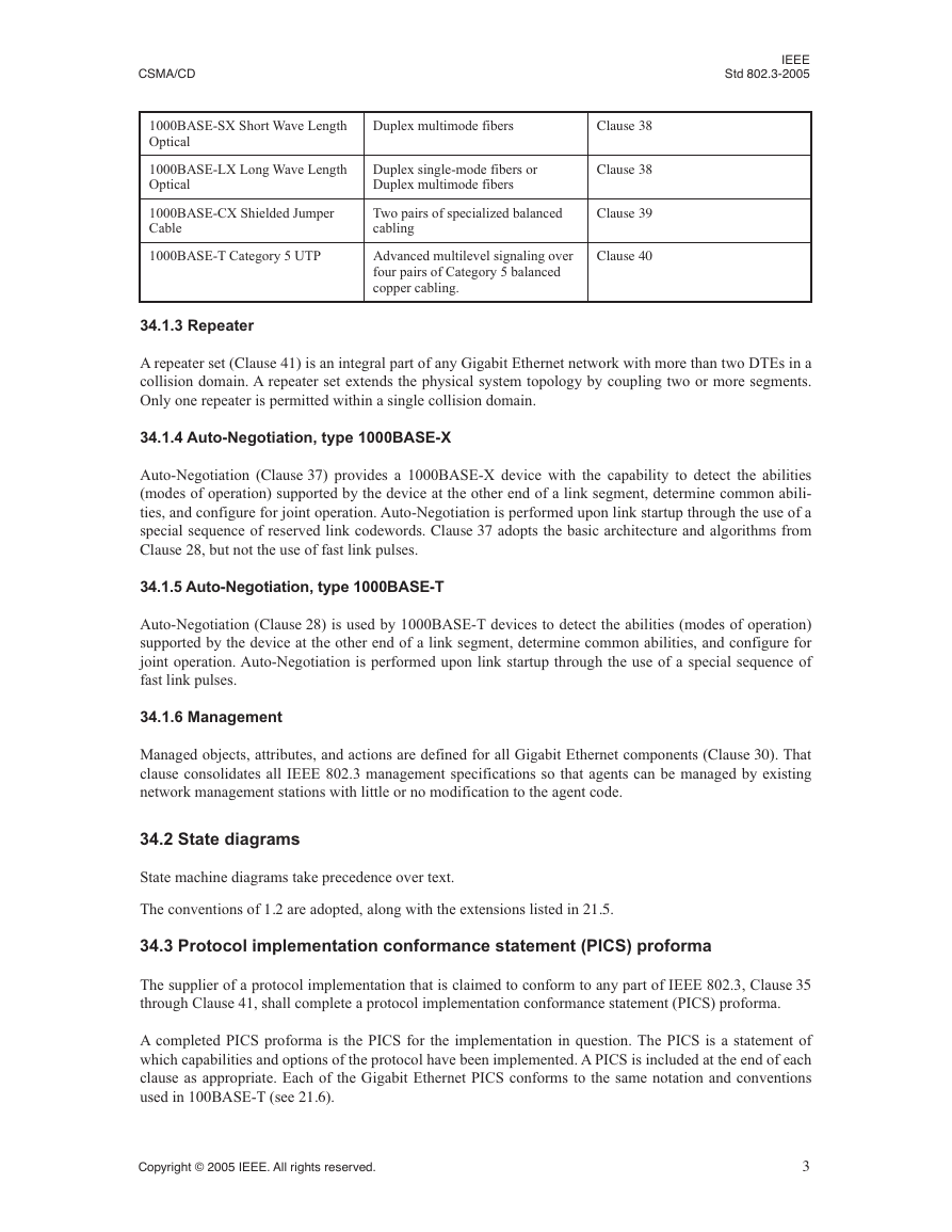
34.1.3 Repeater
34.1.4 Auto-Negotiation, type 1000BASE-X
34.1.5 Auto-Negotiation, type 1000BASE-T
34.1.6 Management
34.2 State diagrams
34.3 Protocol implementation conformance statement (PICS) proforma
34.4 Relation of Gigabit Ethernet to other standards
35. Reconciliation Sublayer (RS) and Gigabit Media Independent Interface (GMII)
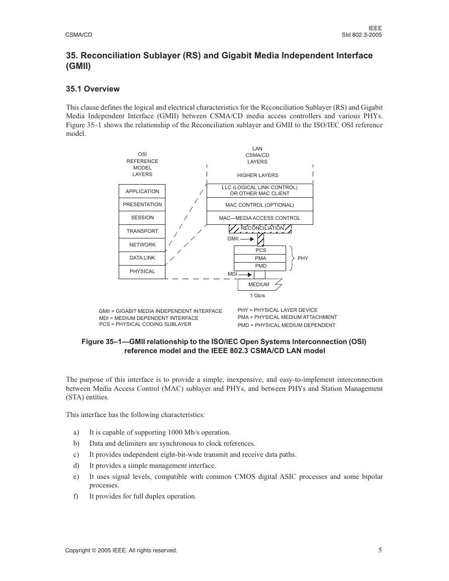
35.1 Overview
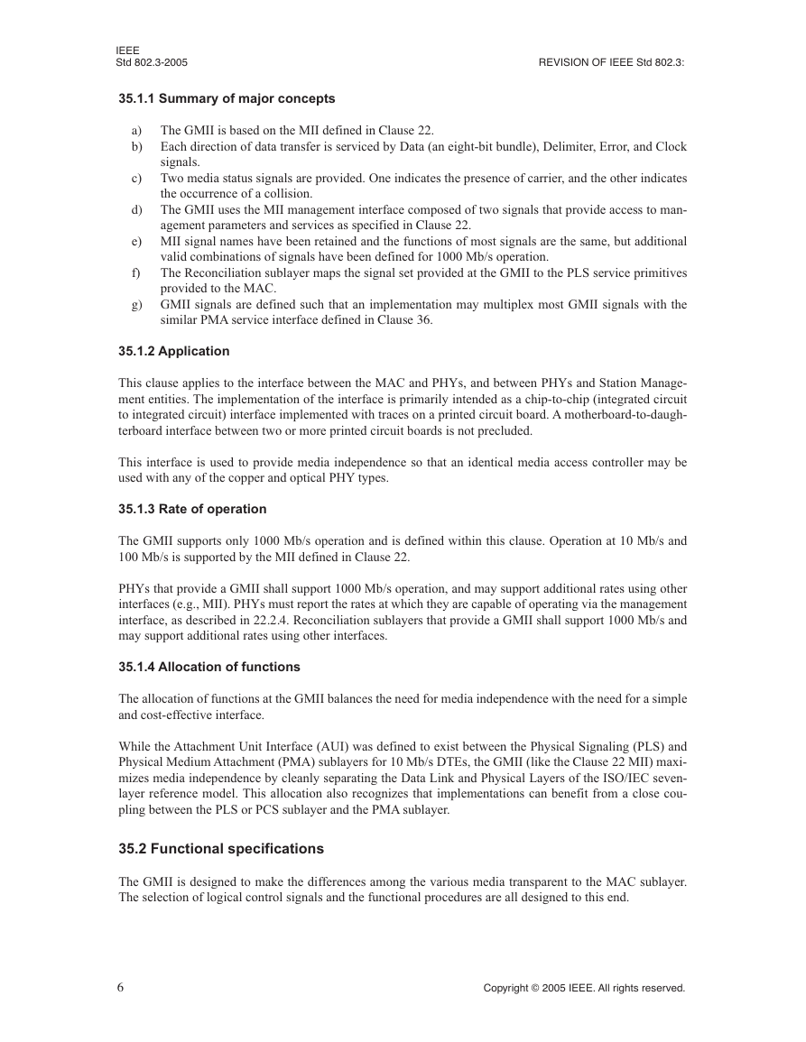
35.1.1 Summary of major concepts
35.1.2 Application
35.1.3 Rate of operation
35.1.4 Allocation of functions
35.2 Functional specifications
35.2.1 Mapping of GMII signals to PLS service primitives and Station Management
35.2.1.1 Mapping of PLS_DATA.request
35.2.1.1.1 Function
35.2.1.1.2 Semantics of the service primitive
35.2.1.1.3 When generated
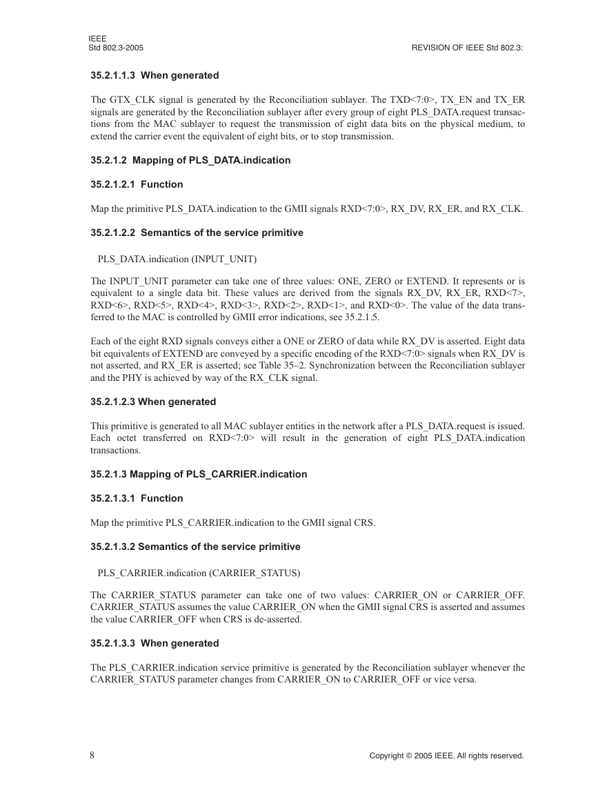
35.2.1.2 Mapping of PLS_DATA.indication
35.2.1.2.1 Function
35.2.1.2.2 Semantics of the service primitive
35.2.1.2.3 When generated
35.2.1.3 Mapping of PLS_CARRIER.indication
35.2.1.3.1 Function
35.2.1.3.2 Semantics of the service primitive
35.2.1.3.3 When generated
35.2.1.4 Mapping of PLS_SIGNAL.indication
35.2.1.4.1 Function
35.2.1.4.2 Semantics of the service primitive
35.2.1.4.3 When generated
35.2.1.5 Response to error indications from GMII
35.2.1.6 Conditions for generation of TX_ER
35.2.1.7 Mapping of PLS_DATA_VALID.indication
35.2.1.7.1 Function
35.2.1.7.2 Semantics of the service primitive
35.2.1.7.3 When generated
35.2.2 GMII signal functional specifications
35.2.2.1 GTX_CLK (1000 Mb/s transmit clock)
35.2.2.2 RX_CLK (receive clock)
35.2.2.3 TX_EN (transmit enable)
35.2.2.4 TXD (transmit data)
35.2.2.5 TX_ER (transmit coding error)
35.2.2.6 RX_DV (receive data valid)
35.2.2.7 RXD (receive data)
35.2.2.8 RX_ER (receive error)
35.2.2.9 CRS (carrier sense)
35.2.2.10 COL (collision detected)
35.2.2.11 MDC (management data clock)
35.2.2.12 MDIO (management data input/output)
35.2.3 GMII data stream
35.2.3.1 Inter-frame
35.2.3.2 Preamble and start of frame delimiter 35.2.3.2.1 Transmit case
35.2.3.2.2 Receive case
35.2.3.3 Data
35.2.3.4 End-of-Frame delimiter
35.2.3.5 Carrier extension
35.2.3.6 Definition of Start of Packet and End of Packet Delimiters
35.2.4 MAC delay constraints (with GMII)
35.2.5 Management functions
35.3 Signal mapping
35.4 Electrical characteristics
35.4.1 DC characteristics
35.4.2 AC characteristics
35.4.2.1 Signal Timing measurements
35.4.2.2 GMII test circuit topology
35.4.2.3 GMII ac specifications
35.5 Protocol implementation conformance statement (PICS) proforma for Clause 35, Reconciliation Sublayer (RS) and Gigabit Media Independent Interface (GMII)
35.5.1 Introduction
35.5.2 Identification
35.5.2.1 Implementation identification
35.5.2.2 Protocol summary
35.5.2.3 Major capabilities/options
35.5.3 PICS proforma tables for reconciliation sublayer and Gigabit Media Independent Interface
35.5.3.1 Mapping of PLS service primitives
35.5.3.2 GMII signal functional specifications
35.5.3.3 Data stream structure
35.5.3.4 Delay constraints
35.5.3.5 Management functions
35.5.3.6 Electrical characteristics
36. Physical Coding Sublayer (PCS) and Physical Medium Attachment (PMA) sublayer, type 1000BASEX
36.1 Overview
36.1.1 Scope
36.1.2 Objectives
36.1.3 Relationship of 1000BASEX to other standards
36.1.4 Summary of 1000BASE-X sublayers
36.1.4.1 Physical Coding Sublayer (PCS)
36.1.4.2 Physical Medium Attachment (PMA) sublayer
36.1.4.3 Physical Medium Dependent (PMD) sublayer
36.1.5 Inter-sublayer interfaces
36.1.6 Functional block diagram
36.1.7 State diagram conventions
36.2 Physical Coding Sublayer (PCS)
36.2.1 PCS Interface (GMII)
36.2.2 Functions within the PCS
36.2.3 Use of code-groups
36.2.4 8B/10B transmission code
36.2.4.1 Notation conventions
36.2.4.2 Transmission order
36.2.4.3 Valid and invalid code-groups
36.2.4.4 Running disparity rules
36.2.4.5 Generating code-groups
36.2.4.6 Checking the validity of received code-groups
36.2.4.7 Ordered_sets
36.2.4.7.1 Ordered_set rules
36.2.4.8 /K28.5/ code-group considerations
36.2.4.9 Comma considerations
36.2.4.10 Configuration (/C/)
36.2.4.11 Data (/D/)
36.2.4.12 IDLE (/I/)
36.2.4.13 Start_of_Packet (SPD) delimiter
36.2.4.14 End_of_Packet delimiter (EPD)
36.2.4.14.1 EPD rules
36.2.4.15 Carrier_Extend (/R/)
36.2.4.15.1 Carrier_Extend rules
36.2.4.16 Error_Propagation (/V/)
36.2.4.17 Encapsulation
36.2.4.18 Mapping between GMII, PCS and PMA
36.2.5 Detailed functions and state diagrams
36.2.5.1 State variables
36.2.5.1.1 Notation conventions
36.2.5.1.2 Constants
36.2.5.1.3 Variables
36.2.5.1.4 Functions
36.2.5.1.5 Counters
36.2.5.1.6 Message
36.2.5.1.7 Timer
36.2.5.2 State diagrams
36.2.5.2.1 Transmit
36.2.5.2.2 Receive
36.2.5.2.3 State variable function carrier_detect(x)
36.2.5.2.4 Code-group stream decoding
36.2.5.2.5 Carrier sense
36.2.5.2.6 Synchronization
36.2.5.2.7 Auto-Negotiation process
36.3 Physical Medium Attachment (PMA) sublayer
36.3.1 Service Interface
36.3.1.1 PMA_UNITDATA.request
36.3.1.1.1 Semantics of the service primitive
36.3.1.1.2 When generated
36.3.1.1.3 Effect of receipt
36.3.1.2 PMA_UNITDATA.indication
36.3.1.2.1 Semantics of the service primitive
36.3.1.2.2 When generated
36.3.1.2.3 Effect of receipt
36.3.2 Functions within the PMA
36.3.2.1 Data delay
36.3.2.2 PMA transmit function
36.3.2.3 PMA receive function
36.3.2.4 Code-group alignment
36.3.3 A physical instantiation of the PMA Service Interface
36.3.3.1 Required signals
36.3.3.2 Summary of control signal usage
36.3.4 General electrical characteristics of the TBI
36.3.4.1 DC characteristics
36.3.4.2 Valid signal levels
36.3.4.3 Rise and fall time definition
36.3.4.4 Output load
36.3.5 TBI transmit interface electrical characteristics
36.3.5.1 Transmit data (tx_code-group<9:0>)
36.3.5.2 TBI transmit interface timing
36.3.6 TBI receive interface electrical characteristics
36.3.6.1 Receive data (rx_code-group<9:0>)
36.3.6.2 Receive clock (PMA_RX_CLK<0>, PMA_RX_CLK<1>)
36.3.7 Loopback mode
36.3.7.1 Receiver considerations
36.3.7.2 Transmitter considerations
36.3.8 Test functions
36.4 Compatibility considerations
36.5 Delay constraints
36.5.1 MDI to GMII delay constraints
36.5.2 DTE delay constraints (half duplex mode)
36.5.3 Carrier de-assertion/assertion constraint (half duplex mode)
36.6 Environmental specifications
36.7 Protocol implementation conformance statement (PICS) proforma for Clause 36, Physical Coding Sublayer (PCS) and Physical Medium Attachment (PMA) sublayer, type 1000BASE-X
36.7.1 Introduction
36.7.2 Identification
36.7.2.1 Implementation identification
36.7.2.2 Protocol summary
36.7.3 Major Capabilities/Options
36.7.4 PICS proforma tables for the PCS and PMA sublayer, type 1000BASE-X
36.7.4.1 Compatibility considerations
36.7.4.2 Code-group functions
36.7.4.3 State diagrams
36.7.4.4 PMA functions
36.7.4.5 PMA transmit function
36.7.4.6 PMA code-group alignment function
36.7.4.7 TBI
36.7.4.8 Delay constraints
37. Auto-Negotiation function, type 1000BASE-X
37.1 Overview
37.1.1 Scope
37.1.2 Application perspective/objectives
37.1.3 Relationship to ISO/IEC 8802-3
37.1.4 Compatibility considerations
37.1.4.1 Auto-Negotiation
37.1.4.2 Management interface
37.1.4.2.1 GMII management interface
37.1.4.3 Interoperability between Auto-Negotiation compatible devices
37.1.4.4 User Configuration with Auto-Negotiation
37.2 Functional specifications
37.2.1 Config_Reg encoding
37.2.1.1 Base page to management register mapping
37.2.1.2 Full duplex
37.2.1.3 Half duplex
37.2.1.4 Pause
37.2.1.5 Remote fault
37.2.1.5.1 No error, link OK
37.2.1.5.2 Offline
37.2.1.5.3 Link_Failure
37.2.1.5.4 Auto-Negotiation_Error
37.2.1.6 Acknowledge
37.2.1.7 Next page
37.2.2 Transmit function requirements
37.2.2.1 Transmit function to Auto-Negotiation process interface requirements
37.2.3 Receive function requirements
37.2.3.1 Receive function to Auto-Negotiation process interface requirements
37.2.4 Arbitration process requirements
37.2.4.1 Renegotiation function
37.2.4.2 Priority resolution function
37.2.4.3 Next Page function
37.2.4.3.1 Next page encodings
37.2.4.3.2 Next page
37.2.4.3.3 Acknowledge
37.2.4.3.4 Message page
37.2.4.3.5 Acknowledge 2
37.2.4.3.6 Toggle
37.2.4.3.7 Message page encoding
37.2.4.3.8 Message Code Field
37.2.4.3.9 Unformatted page encoding
37.2.4.3.10 Unformatted Code Field
37.2.4.3.11 Use of next pages
37.2.4.3.12 Management register requirements
37.2.5 Management function requirements
37.2.5.1 Management registers
37.2.5.1.1 Control register (Register 0)
37.2.5.1.2 Status register (Register 1)
37.2.5.1.3 AN advertisement register (Register 4) (R/W)
37.2.5.1.4 AN link partner ability base page register (Register 5) (RO)
37.2.5.1.5 AN expansion register (Register 6) (RO)
37.2.5.1.6 AN next page transmit register (Register 7)
37.2.5.1.7 AN link partner ability next page register (Register 8)
37.2.5.1.8 Extended status register (Register 15)
37.2.5.1.9 State diagram variable to management register mapping
37.2.5.2 Auto-Negotiation managed object class
37.2.6 Absence of management function
37.3 Detailed functions and state diagrams
37.3.1 State diagram variables
37.3.1.1 Variables
37.3.1.2 Functions
37.3.1.3 Messages
37.3.1.4 Timers
37.3.1.5 State diagrams
37.4 Environmental specifications
37.5 Protocol implementation conformance statement (PICS) proforma for Clause 37, Auto-Negotiation function, type 1000BASE-X
37.5.1 Introduction
37.5.2 Identification
37.5.2.1 Implementation identification
37.5.2.2 Protocol summary
37.5.3 Major Capabilities/Options
37.5.4 PICS proforma tables for the Auto-Negotiation function, type 1000BASE-X
37.5.4.1 Compatibility considerations
37.5.4.2 Auto-Negotiation functions
37.5.4.2.1 Config_Reg
37.5.4.2.2 Remote Fault functions
37.5.4.2.3 AN transmit functions
37.5.4.2.4 AN receive functions
37.5.4.2.5 Priority resolution functions
37.5.4.2.6 Next page functions
37.5.4.2.7 Management registers
38. Physical Medium Dependent (PMD) sublayer and baseband medium, type 1000BASELX (Long Wavelength Laser) and 1000BASESX (Short Wavelength Laser)
38.1 Overview
38.1.1 Physical Medium Dependent (PMD) sublayer service interface
38.1.1.1 PMD_UNITDATA.request
38.1.1.1.1 Semantics of the service primitive
38.1.1.1.2 When generated
38.1.1.1.3 Effect of receipt
38.1.1.2 PMD_UNITDATA.indication
38.1.1.2.1 Semantics of the service primitive
38.1.1.2.2 When generated
38.1.1.2.3 Effect of receipt
38.1.1.3 PMD_SIGNAL.indication
38.1.1.3.1 Semantics of the service primitive
38.1.1.3.2 When generated
38.1.1.3.3 Effect of receipt
38.1.2 Medium Dependent Interface (MDI)
38.2 PMD functional specifications
38.2.1 PMD block diagram
38.2.2 PMD transmit function
38.2.3 PMD receive function
38.2.4 PMD signal detect function
38.3 PMD to MDI optical specifications for 1000BASE-SX
38.3.1 Transmitter optical specifications
38.3.2 Receive optical specifications
38.3.3 Worst-case 1000BASE-SX link power budget and penalties (informative)
38.4 PMD to MDI optical specifications for 1000BASE-LX
38.4.1 Transmitter optical specifications
38.4.2 Receive optical specifications
38.4.3 Worst-case 1000BASE-LX link power budget and penalties (informative)
38.5 Jitter specifications for 1000BASE-SX and 1000BASE-LX
38.6 Optical measurement requirements
38.6.1 Center wavelength and spectral width measurements
38.6.2 Optical power measurements
38.6.3 Extinction ratio measurements
38.6.4 Relative Intensity Noise (RIN)
38.6.5 Transmitter optical waveform (transmit eye)
38.6.6 Transmit rise/fall characteristics
38.6.7 Receive sensitivity measurements
38.6.8 Total jitter measurements
38.6.9 Deterministic jitter measurement (informative)
38.6.10 Coupled Power Ratio (CPR) measurements
38.6.11 Conformance test signal at TP3 for receiver testing
38.6.12 Measurement of the receiver 3 dB electrical upper cutoff frequency
38.7 Environmental specifications
38.7.1 General safety
38.7.2 Laser safety
38.7.3 Installation
38.8 Environment
38.8.1 Electromagnetic emission
38.8.2 Temperature, humidity, and handling
38.9 PMD labeling requirements
38.10 Fiber optic cabling model
38.11 Characteristics of the fiber optic cabling
38.11.1 Optical fiber and cable
38.11.2 Optical fiber connection
38.11.2.1 Connection insertion loss
38.11.2.2 Connection return loss
38.11.3 Medium Dependent Interface (MDI)
38.11.4 Single-mode fiber offset-launch mode-conditioning patch cord for MMF operation of 1000BASE-LX
38.12 Protocol implementation conformance statement (PICS) proforma for Clause 38, Physical Medium Dependent (PMD) sublayer and baseband medium, type 1000BASELX (Long Wavelength Laser) and 1000BASESX (Short Wavelength Laser)
38.12.1 Introduction
38.12.2 Identification
38.12.2.1 Implementation identification
38.12.2.2 Protocol summary
38.12.3 Major capabilities/options
38.12.4 PICS proforma tables for Physical Medium Dependent (PMD) sublayer and baseband medium, type 1000BASELX (Long Wavelength Laser) and 1000BASESX (Short Wavelength Laser)
38.12.4.1 PMD functional specifications
38.12.4.2 PMD to MDI optical specifications for 1000BASE-SX
38.12.4.3 PMD to MDI optical specifications for 1000BASE-LX
38.12.4.4 Jitter specifications
38.12.4.5 Optical measurement requirements
38.12.4.6 Characteristics of the fiber optic cabling
39. Physical Medium Dependent (PMD) sublayer and baseband medium, type 1000BASECX (short-haul copper)
39.1 Overview
39.2 Functional specifications
39.2.1 PMD transmit function
39.2.2 PMD receive function
39.2.3 PMD signal detect function
39.3 PMD to MDI electrical specifications
39.3.1 Transmitter electrical specifications
39.3.2 Receiver electrical specifications
39.3.3 Jitter specifications for 1000BASE-CX
39.4 Jumper cable assembly characteristics
39.4.1 Compensation networks
39.4.2 Shielding
39.5 MDI specification
39.5.1 MDI connectors
39.5.1.1 Style-1 connector specification
39.5.1.2 Style-2 connector specification
39.5.1.3 Style-2 connector example drawing (informative)
39.5.2 Crossover function
39.6 Electrical measurement requirements
39.6.1 Transmit rise/fall time
39.6.2 Transmit skew measurement
39.6.3 Transmit eye (normalized and absolute)
39.6.4 Through_connection impedance
39.6.5 Jumper cable intra-pair differential skew
39.6.6 Receiver link signal
39.6.7 Near-End Cross Talk (NEXT)
39.6.8 Differential time-domain reflectometry (TDR) measurement procedure
39.6.8.1 Driving waveform
39.6.8.2 Calibration of the test setup
39.7 Environmental specifications
39.8 Protocol implementation conformance statement (PICS) proforma for Clause 39, Physical Medium Dependent (PMD) sublayer and baseband medium, type 1000BASECX
39.8.1 Introduction
39.8.2 Identification
39.8.2.1 Implementation identification
39.8.2.2 Protocol summary
39.8.3 Major capabilities/options
39.8.4 PICS proforma tables for Physical Medium Dependent (PMD) sublayer and baseband medium, type 1000BASECX (short-haul copper)
39.8.4.1 PMD functional specifications
39.8.4.2 PMD to MDI electrical specifications
39.8.4.3 Jumper cable assembly characteristics
39.8.4.4 Other requirements
40. Physical Coding Sublayer (PCS), Physical Medium Attachment (PMA) sublayer and baseband medium, type 1000BASE-T
40.1 Overview
40.1.1 Objectives
40.1.2 Relationship of 1000BASE-T to other standards
40.1.3 Operation of 1000BASE-T
40.1.3.1 Physical Coding Sublayer (PCS)
40.1.3.2 Physical Medium Attachment (PMA) sublayer
40.1.4 Signaling
40.1.5 Inter-sublayer interfaces
40.1.6 Conventions in this clause
40.2 1000BASE-T Service Primitives and Interfaces
40.2.1 Technology-Dependent Interface
40.2.1.1 PMA_LINK.request
40.2.1.1.1 Semantics of the primitive
40.2.1.1.2 When generated
40.2.1.1.3 Effect of receipt
40.2.1.2 PMA_LINK.indication
40.2.1.2.1 Semantics of the primitive
40.2.1.2.2 When generated
40.2.1.2.3 Effect of receipt
40.2.2 PMA Service Interface
40.2.3 PMA_TXMODE.indication
40.2.3.1 Semantics of the primitive
40.2.3.2 When generated
40.2.3.3 Effect of receipt
40.2.4 PMA_CONFIG.indication
40.2.4.1 Semantics of the primitive
40.2.4.2 When generated
40.2.4.3 Effect of receipt
40.2.5 PMA_UNITDATA.request
40.2.5.1 Semantics of the primitive
40.2.5.2 When generated
40.2.5.3 Effect of receipt
40.2.6 PMA_UNITDATA.indication
40.2.6.1 Semantics of the primitive
40.2.6.2 When generated
40.2.6.3 Effect of receipt
40.2.7 PMA_SCRSTATUS.request
40.2.7.1 Semantics of the primitive
40.2.7.2 When generated
40.2.7.3 Effect of receipt
40.2.8 PMA_RXSTATUS.indication
40.2.8.1 Semantics of the primitive
40.2.8.2 When generated
40.2.8.3 Effect of receipt
40.2.9 PMA_REMRXSTATUS.request
40.2.9.1 Semantics of the primitive
40.2.9.2 When generated
40.2.9.3 Effect of receipt
40.2.10 PMA_RESET.indication
40.2.10.1 When generated
40.2.10.2 Effect of receipt
40.3 Physical Coding Sublayer (PCS)
40.3.1 PCS functions
40.3.1.1 PCS Reset function
40.3.1.2 PCS Data Transmission Enable
40.3.1.3 PCS Transmit function
40.3.1.3.1 Side-stream scrambler polynomials
40.3.1.3.2 Generation of bits Sxn[3:0], Syn[3:0], and Sgn[3:0]
40.3.1.3.3 Generation of bits Scn[7:0]
40.3.1.3.4 Generation of bits Sdn[8:0]
40.3.1.3.5 Generation of quinary symbols TAn, TBn, TCn, TDn
40.3.1.3.6 Generation of An, Bn, Cn, Dn
40.3.1.4 PCS Receive function
40.3.1.4.1 Decoding of code-groups
40.3.1.4.2 Receiver descrambler polynomials
40.3.1.5 PCS Carrier Sense function
40.3.2 Stream structure
40.3.3 State variables
40.3.3.1 Variables
40.3.3.2 Functions
40.3.3.3 Timer
40.3.3.4 Messages
40.3.4 State diagrams
40.3.4.1 Supplement to state diagram
40.4 Physical Medium Attachment (PMA) sublayer
40.4.1 PMA functional specifications
40.4.2 PMA functions
40.4.2.1 PMA Reset function
40.4.2.2 PMA Transmit function
40.4.2.3 PMA Receive function
40.4.2.4 PHY Control function
40.4.2.5 Link Monitor function
40.4.2.6 Clock Recovery function
40.4.3 MDI
40.4.3.1 MDI signals transmitted by the PHY
40.4.3.2 Signals received at the MDI
40.4.4 Automatic MDI/MDI-X Configuration
40.4.4.1 Description of Automatic MDI/MDI-X state machine
40.4.4.2 Pseudo-random sequence generator
40.4.5 State variables
40.4.5.1 State diagram variables
40.4.5.2 Timers
40.4.6 State Diagrams
40.4.6.1 PHY Control state diagram
40.4.6.2 Link Monitor state diagram
40.4.6.2.1 Auto Crossover state diagram
40.5 Management interface
40.5.1 Support for Auto-Negotiation
40.5.1.1 1000BASE-T use of registers during Auto-Negotiation
40.5.1.2 1000BASE-T Auto-Negotiation page use
40.5.1.3 Sending Next Pages
40.5.2 MASTERSLAVE configuration resolution
40.6 PMA electrical specifications
40.6.1 PMA-to-MDI interface tests
40.6.1.1 Isolation requirement
40.6.1.1.1 Test channel
40.6.1.1.2 Test modes
40.6.1.1.3 Test Fixtures
40.6.1.2 Transmitter electrical specifications
40.6.1.2.1 Peak differential output voltage and level accuracy
40.6.1.2.2 Maximum output droop
40.6.1.2.3 Differential output templates
40.6.1.2.4 Transmitter distortion
40.6.1.2.5 Transmitter timing jitter
40.6.1.2.6 Transmit clock frequency
40.6.1.3 Receiver electrical specifications
40.6.1.3.1 Receiver differential input signals
40.6.1.3.2 Receiver frequency tolerance
40.6.1.3.3 Common-mode noise rejection
40.6.1.3.4 Alien Crosstalk noise rejection
40.7 Link segment characteristics
40.7.1 Cabling system characteristics
40.7.2 Link transmission parameters
40.7.2.1 Insertion loss
40.7.2.2 Differential characteristic impedance
40.7.2.3 Return loss
40.7.3 Coupling parameters
40.7.3.1 Near-End Crosstalk (NEXT)
40.7.3.1.1 Differential Near-End Crosstalk
40.7.3.2 Far-End Crosstalk (FEXT)
40.7.3.2.1 Equal Level Far-End Crosstalk (ELFEXT) loss
40.7.3.2.2 Multiple Disturber Equal Level Far-End Crosstalk (MDELFEXT) loss
40.7.3.2.3 Multiple-Disturber Power Sum Equal Level Far-End Crosstalk (PSELFEXT) loss
40.7.4 Delay
40.7.4.1 Maximum link delay
40.7.4.2 Link delay skew
40.7.5 Noise environment
40.7.6 External coupled noise
40.8 MDI specification
40.8.1 MDI connectors
40.8.2 Crossover function
40.8.3 MDI electrical specifications
40.8.3.1 MDI return loss
40.8.3.2 MDI impedance balance
40.8.3.3 MDI common-mode output voltage
40.8.3.4 MDI fault tolerance
40.9 Environmental specifications
40.9.1 General safety
40.9.2 Network safety
40.9.2.1 Installation
40.9.2.2 Installation and maintenance guidelines
40.9.2.3 Telephony voltages
40.9.3 Environment
40.9.3.1 Electromagnetic emission
40.9.3.2 Temperature and humidity
40.10 PHY labeling
40.11 Delay constraints
40.11.1 MDI to GMII delay constraints
40.11.2 DTE delay constraints (half duplex only)
40.11.3 Carrier de-assertion/assertion constraint (half duplex mode)
40.12 Protocol implementation conformance statement (PICS) proforma for Clause 40-Physical coding sublayer (PCS), physical medium attachment (PMA) sublayer and baseband medium, type 1000BASE-T
40.12.1 Identification
40.12.1.1 Implementation identification
40.12.1.2 Protocol summary
40.12.2 Major capabilities/options
40.12.3 Clause conventions
40.12.4 Physical Coding Sublayer (PCS)
40.12.4.1 PCS receive functions
40.12.4.2 Other PCS functions
40.12.5 Physical Medium Attachment (PMA)
40.12.6 Management interface
40.12.6.1 1000BASE-T Specific Auto-Negotiation Requirements
40.12.7 PMA Electrical Specifications
40.12.8 Characteristics of the link segment
40.12.9 MDI requirements
40.12.10 General safety and environmental requirements
40.12.11 Timing requirements
41. Repeater for 1000 Mb/s baseband networks
41.1 Overview
41.1.1 Scope
41.1.1.1 Repeater set
41.1.1.2 Repeater unit
41.1.2 Application perspective
41.1.2.1 Objectives
41.1.2.2 Compatibility considerations
41.1.2.2.1 Internal segment compatibility
41.1.3 Relationship to PHY
41.2 Repeater functional specifications
41.2.1 Repeater functions
41.2.1.1 Signal restoration functional requirements
41.2.1.1.1 Signal amplification
41.2.1.1.2 Signal wave-shape restoration
41.2.1.1.3 Signal retiming
41.2.1.2 Data-handling functional requirements
41.2.1.2.1 Data frame forwarding
41.2.1.2.2 Received code violations
41.2.1.3 Received event-handling functional requirements
41.2.1.3.1 Received event handling
41.2.1.3.2 Preamble regeneration
41.2.1.3.3 Start-of-packet propagation delay
41.2.1.3.4 Start-of-packet variability
41.2.1.4 Collision-handling functional requirements
41.2.1.4.1 Collision detection
41.2.1.4.2 Jam generation
41.2.1.4.3 Start-of-collision-jam propagation delay
41.2.1.4.4 Cessation-of-collision Jam propagation delay
41.2.1.5 Error-handling functional requirements
41.2.1.5.1 Carrier integrity functional requirements
41.2.1.5.2 Speed handling
41.2.1.6 Partition functional requirements
41.2.1.7 Receive jabber functional requirements
41.2.2 Detailed repeater functions and state diagrams
41.2.2.1 State diagram variables
41.2.2.1.1 Constants
41.2.2.1.2 Variables
41.2.2.1.3 Functions
41.2.2.1.4 Timers
41.2.2.1.5 Counters
41.2.2.1.6 Port designation
41.2.2.2 State diagrams
41.3 Repeater electrical specifications
41.3.1 Electrical isolation
41.4 Environmental specifications
41.4.1 General safety
41.4.2 Network safety
41.4.2.1 Installation
41.4.2.2 Grounding
41.4.2.3 Installation and maintenance guidelines
41.4.3 Electrical isolation
41.4.3.1 Environment A requirements
41.4.3.2 Environment B requirements
41.4.4 Reliability
41.4.5 Environment
41.4.5.1 Electromagnetic emission
41.4.5.2 Temperature and humidity
41.5 Repeater labeling
41.6 Protocol implementation conformance statement (PICS) proforma for Clause 41, Repeater for 1000 Mb/s baseband networks
41.6.1 Introduction
41.6.2 Identification
41.6.2.1 Implementation identification
41.6.2.2 Protocol summary
41.6.3 Major capabilities/options
41.6.4 PICS proforma tables for the Repeater for 1000 Mb/s baseband networks
41.6.4.1 Compatibility considerations
41.6.4.2 Repeater functions
41.6.4.3 Signal restoration function
41.6.4.4 Data-Handling function
41.6.4.5 Receive Event-Handling function
41.6.4.6 Collision-Handling function
41.6.4.7 Error-Handling function
41.6.4.8 Partition function
41.6.4.9 Receive Jabber function
41.6.4.10 Repeater state diagrams
41.6.4.11 Repeater electrical
41.6.4.12 Repeater labeling
42. System considerations for multisegment 1000 Mb/s networks
42.1 Overview
42.1.1 Single collision domain multisegment networks
42.1.2 Repeater usage
42.2 Transmission System Model 1
42.3 Transmission System Model 2
42.3.1 Round-trip collision delay
42.3.1.1 Worst-case path delay value (PDV) selection
42.3.1.2 Worst-case PDV calculation
42.4 Full duplex 1000 Mb/s topology limitations
43. Link Aggregation
43.1 Overview
43.1.1 Terminology
43.1.2 Goals and objectives
43.1.3 Positioning of Link Aggregation within the IEEE 802.3 architecture
43.1.4 State diagram conventions
43.2 Link Aggregation operation
43.2.1 Principles of Link Aggregation
43.2.2 Service interfaces
43.2.3 Frame Collector
43.2.3.1 Frame Collector state diagram
43.2.3.1.1 Constants
43.2.3.1.2 Variables
43.2.3.1.3 Messages
43.2.3.1.4 State diagram
43.2.4 Frame Distributor
43.2.4.1 Frame Distributor state diagram
43.2.4.1.1 Variables
43.2.4.1.2 Messages
43.2.4.1.3 State diagram
43.2.5 Marker Generator/Receiver (optional)
43.2.6 Marker Responder
43.2.7 Aggregator Parser/Multiplexer
43.2.7.1 Aggregator Parser state diagram
43.2.7.1.1 Constants
43.2.7.1.2 Variables
43.2.7.1.3 Messages
43.2.8 Aggregator
43.2.8.1 State diagram
43.2.9 Control Parser/Multiplexer
43.2.9.1 Control Parser state diagram
43.2.9.1.1 Constants
43.2.9.1.2 Variables
43.2.9.1.3 Messages
43.2.9.1.4 State diagram
43.2.10 Addressing
43.3 Link Aggregation Control
43.3.1 Characteristics of Link Aggregation Control
43.3.2 System identification
43.3.3 Aggregator identification
43.3.4 Port identification
43.3.5 Capability identification
43.3.6 Link Aggregation Group identification
43.3.6.1 Construction of the Link Aggregation Group Identifier
43.3.6.2 Representation of the Link Aggregation Group Identifier
43.3.7 Selecting a Link Aggregation Group
43.3.8 Agreeing on a Link Aggregation Group
43.3.9 Attaching a link to an Aggregator
43.3.10 Signaling readiness to transfer user data
43.3.11 Enabling Collection and Distribution
43.3.12 Monitoring the membership of a Link Aggregation Group
43.3.13 Detaching a link from an Aggregator
43.3.14 Configuration and administrative control of Link Aggregation
43.3.15 Link Aggregation Control state information
43.4 Link Aggregation Control Protocol (LACP)
43.4.1 LACP design elements
43.4.2 LACPDU structure and encoding
43.4.2.1 Transmission and representation of octets
43.4.2.2 LACPDU structure
43.4.3 LACP state machine overview
43.4.4 Constants
43.4.5 Variables associated with the System
43.4.6 Variables associated with each Aggregator
43.4.7 Variables associated with each port
43.4.8 Variables used for managing the operation of the state machines
43.4.9 Functions
43.4.10 Timers
43.4.11 Messages
43.4.12 Receive machine
43.4.13 Periodic Transmission machine
43.4.14 Selection Logic
43.4.14.1 Selection Logic-Requirements
43.4.14.2 Selection Logic-Recommended default operation
43.4.15 Mux machine
43.4.16 Transmit machine
43.4.17 Churn Detection machines
43.5 Marker protocol
43.5.1 Introduction
43.5.2 Sequence of operations
43.5.3 Marker and Marker Response PDU structure and encoding
43.5.3.1 Transmission and representation of octets
43.5.3.2 Marker and Marker Response PDU structure
43.5.4 Protocol definition
43.5.4.1 Operation of the marker protocol
43.5.4.2 Marker Responder state diagram
43.5.4.2.1 Constants
43.5.4.2.2 Variables
43.5.4.2.3 Messages
43.6 Configuration capabilities and restrictions
43.6.1 Use of system and port priorities
43.6.2 Dynamic allocation of operational Keys
43.6.3 Link Aggregation on shared-medium links
43.6.4 Selection Logic variants
43.6.4.1 Reduced reconfiguration
43.6.4.2 Limited Aggregator availability
43.7 Protocol implementation conformance statement (PICS) proforma for Clause 43, Aggregation of Multiple Link Segments
43.7.1 Introduction
43.7.2 Identification
43.7.2.1 Implementation identification
43.7.2.2 Protocol summary
43.7.3 Major capabilities/options
43.7.4 Frame Collector
43.7.5 Frame Distributor
43.7.6 Marker protocol
43.7.7 Aggregator Parser/Multiplexer
43.7.8 Control Parser/Multiplexer
43.7.9 System identification
43.7.10 Aggregator identification
43.7.11 Port identification
43.7.12 Capability identification
43.7.13 Link Aggregation Group identification
43.7.14 Detaching a link from an Aggregator
43.7.15 LACPDU structure
43.7.16 State machine variables
43.7.17 Receive machine
43.7.18 Periodic Transmission machine
43.7.19 Selection Logic
43.7.20 Mux machine
43.7.21 Transmit machine
43.7.22 Churn Detection machines
43.7.23 Marker protocol
43.7.24 Configuration capabilities and restrictions
43.7.25 Link Aggregation on shared-medium links
Annex 36A (informative)—Jitter test patterns
Jitter test patterns
36A.1 High-frequency test pattern
36A.2 Low-frequency test pattern
36A.3 Mixed frequency test pattern
36A.4 Long continuous random test pattern
36A.5 Short continuous random test pattern
Annex 36B (informative)—8B/10B transmission code running disparity calculation examples
8B/10B transmission code running disparity calculation examples
Annex 38A (informative)—Fiber launch conditions
Fiber launch conditions
38A.1 Overfilled Launch
38A.2 Radial Overfilled Launch (ROFL)
Annex 40A (informative)—Additional cabling design guidelines
Additional cabling design guidelines
40A.1 Alien crosstalk
40A.1.1 Multipair cabling (i.e., greater than 4-pair)
40A.1.2 Bundled or hybrid cable configurations
40A.2 Cabling configurations
Annex 40B (informative)—Description of cable clamp
Description of cable clamp
40B.1 Cable clamp validation
Annex 40C (informative)—Add-on interface for additional Next Pages
Add-on interface for additional Next Pages
40C.1 State variables
40C.2 State diagrams
40C.2.1 Auto-Negotiation Transmit state machine add-on for 1000BASE-T
40C.2.2 Auto-Negotiation Receive state diagram add-on for 1000BASE-T
Annex 43A (informative)—Collection and Distribution functions
Collection and Distribution functions
43A.1 Introduction
43A.2 Port selection
43A.3 Dynamic reallocation of conversations to different ports
43A.4 Topology considerations in the choice of distribution algorithm
Annex 43B (normative)—Requirements for support of Slow Protocols
Requirements for support of Slow Protocols
43B.1 Introduction and rationale
43B.2 Slow Protocol transmission characteristics
43B.3 Addressing
43B.4 Protocol identification
43B.5 Handling of Slow Protocol frames
43B.6 Protocol implementation conformance statement (PICS) proforma for Annex 43B, Requirements for support of Slow Protocols
43B.6.1 Introduction
43B.6.2 Identification
43B.6.2.1 Implementation identification
43B.6.2.2 Protocol summary
43B.6.2.3 Transmission characteristics
43B.6.2.4 Frame handling
Annex 43C (informative)—LACP standby link selection and dynamic Key management
LACP standby link selection and dynamic Key management
43C.1 Introduction
43C.2 Goals
43C.3 Standby link selection
43C.4 Dynamic Key management
43C.5 A dynamic Key management algorithm
43C.6 Example 1
43C.7 Example 2




 2023年江西萍乡中考道德与法治真题及答案.doc
 2012年重庆南川中考生物真题及答案.doc
 2013年江西师范大学地理学综合及文艺理论基础考研真题.doc
 2020年四川甘孜小升初语文真题及答案I卷.doc
 2020年注册岩土工程师专业基础考试真题及答案.doc
 2023-2024学年福建省厦门市九年级上学期数学月考试题及答案.doc
 2021-2022学年辽宁省沈阳市大东区九年级上学期语文期末试题及答案.doc
 2022-2023学年北京东城区初三第一学期物理期末试卷及答案.doc
 2018上半年江西教师资格初中地理学科知识与教学能力真题及答案.doc
 2012年河北国家公务员申论考试真题及答案-省级.doc
 2020-2021学年江苏省扬州市江都区邵樊片九年级上学期数学第一次质量检测试题及答案.doc
 2022下半年黑龙江教师资格证中学综合素质真题及答案.doc