logo资料库

UFS-3.0 存储IP资料.pdf

第1页 / 共45页
第2页 / 共45页
第3页 / 共45页
第4页 / 共45页
第5页 / 共45页
第6页 / 共45页
第7页 / 共45页
第8页 / 共45页
资料共45页,剩余部分请下载后查看
1 Introduction
1.1 About UFS Standard
1.2 Arasan’s Contribution to MIPI
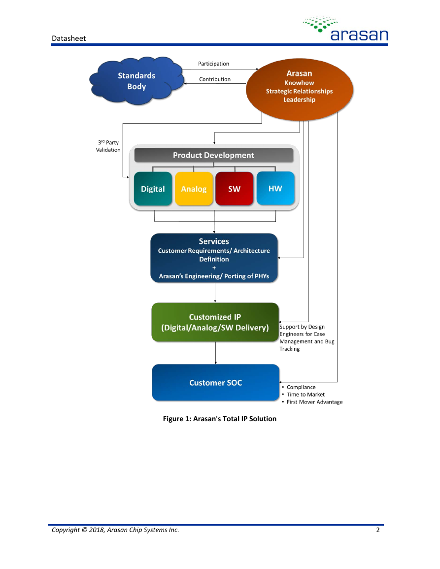
1.3 Arasan’s Total IP Solution
2 UFS 3.0 Host IP
2.1 Overview
2.2 Features
2.3 Architecture
2.3.1 Functional Description
2.3.2 Functional Block Diagram
2.3.3 Functional Block Diagram Description
2.3.3.1 PHY Adapter Layer (L1.5)
2.3.3.2 Data Link Layer (L2)
2.3.3.3 Network Layer (L3)
2.3.3.4 Transport Layer (L4)
2.3.3.5 Device Management Entity (DME)
2.3.3.6 UFS Host Registers
2.3.3.7 UFS Host Controller Interface
2.3.3.8 UFS Transport Protocol Layer
2.3.3.9 System Bus Interface Unit
2.3.3.10 M-PHY
2.4 PIN Diagram
2.5 IP Deliverables
3 UFS 3.0 Device IP
3.1 Features
3.2 Architecture
3.2.1 Functional Description
3.2.2 Functional Block Diagram
3.2.3 Functional Block Diagram Description
3.2.3.1 PHY Adapter Layer (L1.5)
3.2.3.2 Data Link Layer (L2)
3.2.3.3 Network Layer (L3)
3.2.3.4 Transport Layer (L4)
3.2.3.5 Device Management Entity (DME)
3.2.3.6 UFS Device Registers
3.2.3.7 UFS Device Controller Interface
3.2.3.8 UFS Transport Protocol Layer
3.2.3.9 System Bus Interface Unit
3.3 PIN Diagram
3.4 Soc Level Integration
3.4.1 IP Deliverables
3.4.2 Verification Environment
4 UniPro 1.8
4.1 Overview
4.2 Features
4.3 UniPro System Bus
4.4 Architecture
4.4.1 Functional Block Diagram
4.4.2 Functional Block Diagram Description
4.4.2.1 System Bus Interface Unit
4.4.2.2 DMA Registers
4.4.2.3 DMA Controller
4.4.2.4 Device Management Entity (DME)
4.4.2.5 Test Feature
4.4.2.6 Transport and Network Layers
4.4.2.7 Data Link Layer
4.4.2.8 PHY Adaptor Layer
4.5 PIN Diagram
4.6 Configurable Features
4.7 Deliverables
5 M-PHY 4.1
5.1 Overview
5.1.1 Lanes
5.1.2 Signaling
5.1.3 Line Coding
5.1.4 M-PHY Type
5.2 Overview of Arasan M-PHY for UFS
5.3 Arasan’s M-PHY for UFS Features
5.4 M-PHY Pad Table
5.4.1 Functional Description of M-PHY Pads for Tx Lane
5.4.2 Functional Description of M-PHY Pads for Rx Lane
5.4.3 UFS Specific Pin
5.4.4 Impedance Precision Specific Pin
5.4.5 Protocol Interface (PIF) Signals
5.5 Power Pads
5.6 Hard Macro Deliverables
6 UFS 3.0 Software Stack & Driver
6.1 Overview
6.2 Features
6.3 Architecture
6.4 Deliverbles
7 UFS 3.0 Hardware Validation Platform
7.1 Overview
7.2 Features
7.3 Description
7.4 Deliverables
8 UFS Verification IP (VIP)
8.1 UVM Verification Environment
8.1.1 UVM Verification Environment Components
8.1.1.1 UFS Host Virtual Sequencer
8.1.1.2 AXI UVC Master Env
8.1.1.3 AXI UVC Slave Env
8.1.1.4 UFS Host TB Monitors
8.1.1.5 UFS Device Env
8.1.1.6 Scoreboard
8.1.1.7 Local Scoreboard
8.1.1.8 Coverage Model
8.1.2 UFS Host UVM Model
8.1.3 UFS Device UVM Model
8.1.4 Verification Deliverables
8.2 Verilog Verification Environment
8.2.1 Generator
8.2.2 Scoreboard
8.2.3 AHB Master Model
8.2.4 AXI Slave Model
8.2.5 UniPro Function Model
8.2.6 MPHY Function Model
8.2.7 DUT
8.2.7.1 DMA Controller
8.2.7.2 FIFO Interface
8.2.7.3 Unipro Layers
9 Services & Support
9.1 Global Support
9.2 Arasan Support Team
9.3 Professional Services & Customization
9.4 The Arasan Porting Engine
9.5 Pricing & Licensing
Datasheet UFS 3.0 Total IP Solution UFS Spec v3.0 Compliant UniPro Spec v1.8 Compliant M-PHY Spec v4.1 Compliant Arasan Chip Systems Inc. 2150 North First Street, Suite #240, San Jose, CA 95131 Ph: 408-282-1600 Fax: 408-282-7800 www.arasan.com
Datasheet Disclaimer This document is written in good faith with the intent to assist the readers in the use of the product. Circuit diagrams and other information relating to Arasan Chip Systems’ products are included as a means of illustrating typical applications. Although the information has been checked and is believed to be accurate, no responsibility is assumed for inaccuracies. Information contained in this document is subject to continuous improvement and development. Arasan Chip Systems’ products are not designed, intended, authorized or warranted for use in any life support or other application where product failure could cause or contribute to personal injury or severe property damage. Any and all such uses without prior written approval of an Officer of Arasan Chip Systems Inc. will be fully at the risk of the customer. Arasan Chip Systems Inc. disclaims and excludes any and all warranties, including, without limitation, any and all implied warranties of merchantability, fitness for a particular purpose, title, and infringement and the like, and any and all warranties arising from any course or dealing or usage of trade. This document may not be copied, reproduced, or transmitted to others in any manner. Nor may any use of information in this document be made, except for the specific purposes for which it is transmitted to the recipient, without the prior written consent of Arasan Chip Systems Inc. This specification is subject to change at any time without notice. Arasan Chip Systems Inc. is not responsible for any errors contained herein. In no event shall Arasan Chip Systems Inc. be liable for any direct, indirect, incidental, special, punitive, or consequential damages; or for loss of data, profits, savings or revenues of any kind; regardless of the form of action, whether based on contract; tort; negligence of Arasan Chip Systems Inc or others; strict liability; breach of warranty; or otherwise; whether or not any remedy of buyers is held to have failed of its essential purpose, and whether or not Arasan Chip Systems Inc. has been advised of the possibility of such damages. Restricted Rights Use, duplication, or disclosure by the Government is subject to restrictions as set forth in FAR52.227-14 and DFAR252.227-7013 et seq. or its successor. Copyright Notice No part of this specification may be reproduced in any form or means, without the prior written consent of Arasan Chip Systems, Inc. Questions or comments may be directed to: Arasan Chip Systems Inc. 2150 North First Street, Suite 240 San Jose, CA 95131 Ph: 408-282-1600 Fax: 408-282-7800 Email: sales@arasan.com Copyright © 2018, Arasan Chip Systems Inc.
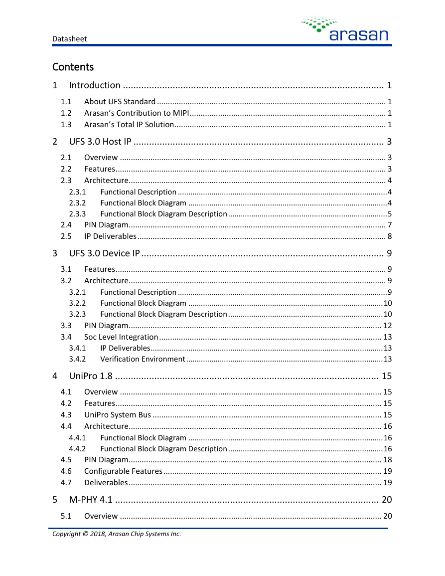
Datasheet Contents 1 3.4.1 3.4.2 4.4.1 4.4.2 4.5 4.6 4.7 2.4 2.5 3.1 3.2 3.3 3.4 1.1 1.2 1.3 2.3.1 2.3.2 2.3.3 Introduction .................................................................................................... 1 About UFS Standard ......................................................................................................... 1 Arasan’s Contribution to MIPI .......................................................................................... 1 Arasan’s Total IP Solution ................................................................................................. 1 2 UFS 3.0 Host IP ................................................................................................ 3 2.1 Overview .......................................................................................................................... 3 2.2 Features ............................................................................................................................ 3 Architecture ...................................................................................................................... 4 2.3 Functional Description .................................................................................................... 4 Functional Block Diagram ............................................................................................... 4 Functional Block Diagram Description ............................................................................ 5 PIN Diagram ...................................................................................................................... 7 IP Deliverables .................................................................................................................. 8 3 UFS 3.0 Device IP ............................................................................................. 9 Features ............................................................................................................................ 9 Architecture ...................................................................................................................... 9 Functional Description .................................................................................................... 9 Functional Block Diagram ............................................................................................. 10 Functional Block Diagram Description .......................................................................... 10 PIN Diagram .................................................................................................................... 12 Soc Level Integration ...................................................................................................... 13 IP Deliverables ............................................................................................................... 13 Verification Environment .............................................................................................. 13 4 UniPro 1.8 ..................................................................................................... 15 4.1 Overview ........................................................................................................................ 15 4.2 Features .......................................................................................................................... 15 4.3 UniPro System Bus ......................................................................................................... 15 Architecture .................................................................................................................... 16 4.4 Functional Block Diagram ............................................................................................. 16 Functional Block Diagram Description .......................................................................... 16 PIN Diagram .................................................................................................................... 18 Configurable Features .................................................................................................... 19 Deliverables .................................................................................................................... 19 5 M-PHY 4.1 ..................................................................................................... 20 5.1 Overview ........................................................................................................................ 20 3.2.1 3.2.2 3.2.3 Copyright © 2018, Arasan Chip Systems Inc.
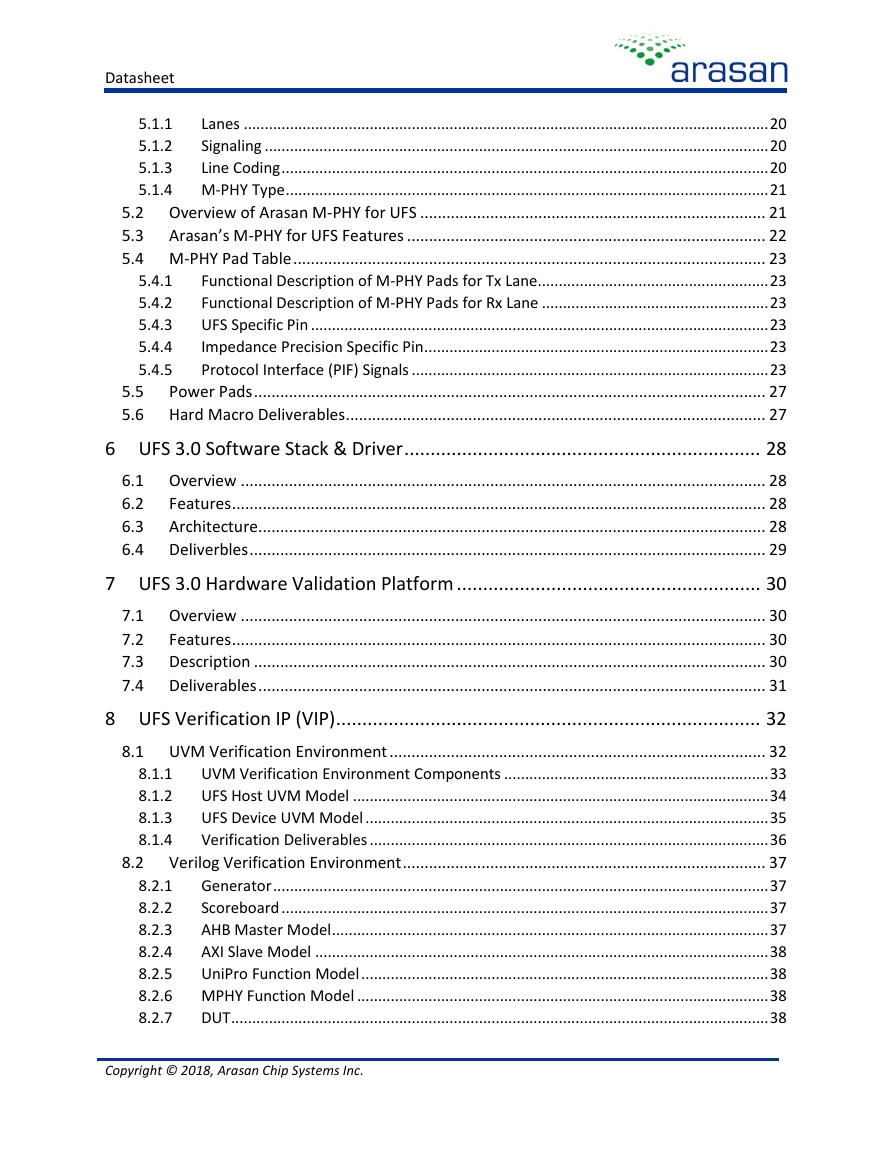
Datasheet 5.4.1 5.4.2 5.4.3 5.4.4 5.4.5 Lanes ............................................................................................................................. 20 5.1.1 Signaling ........................................................................................................................ 20 5.1.2 5.1.3 Line Coding .................................................................................................................... 20 5.1.4 M-PHY Type ................................................................................................................... 21 5.2 Overview of Arasan M-PHY for UFS ............................................................................... 21 5.3 Arasan’s M-PHY for UFS Features .................................................................................. 22 5.4 M-PHY Pad Table ............................................................................................................ 23 Functional Description of M-PHY Pads for Tx Lane ....................................................... 23 Functional Description of M-PHY Pads for Rx Lane ...................................................... 23 UFS Specific Pin ............................................................................................................. 23 Impedance Precision Specific Pin .................................................................................. 23 Protocol Interface (PIF) Signals ..................................................................................... 23 Power Pads ..................................................................................................................... 27 5.5 5.6 Hard Macro Deliverables ................................................................................................ 27 6 UFS 3.0 Software Stack & Driver .................................................................... 28 6.1 Overview ........................................................................................................................ 28 Features .......................................................................................................................... 28 6.2 Architecture .................................................................................................................... 28 6.3 6.4 Deliverbles ...................................................................................................................... 29 7 UFS 3.0 Hardware Validation Platform .......................................................... 30 7.1 Overview ........................................................................................................................ 30 Features .......................................................................................................................... 30 7.2 Description ..................................................................................................................... 30 7.3 7.4 Deliverables .................................................................................................................... 31 8 UFS Verification IP (VIP) ................................................................................. 32 8.1 UVM Verification Environment ...................................................................................... 32 UVM Verification Environment Components ............................................................... 33 UFS Host UVM Model ................................................................................................... 34 UFS Device UVM Model ................................................................................................ 35 Verification Deliverables ............................................................................................... 36 Verilog Verification Environment ................................................................................... 37 Generator ...................................................................................................................... 37 8.2.1 Scoreboard .................................................................................................................... 37 8.2.2 AHB Master Model ........................................................................................................ 37 8.2.3 AXI Slave Model ............................................................................................................ 38 8.2.4 8.2.5 UniPro Function Model ................................................................................................. 38 8.2.6 MPHY Function Model .................................................................................................. 38 DUT ................................................................................................................................ 38 8.2.7 8.1.1 8.1.2 8.1.3 8.1.4 8.2 Copyright © 2018, Arasan Chip Systems Inc.
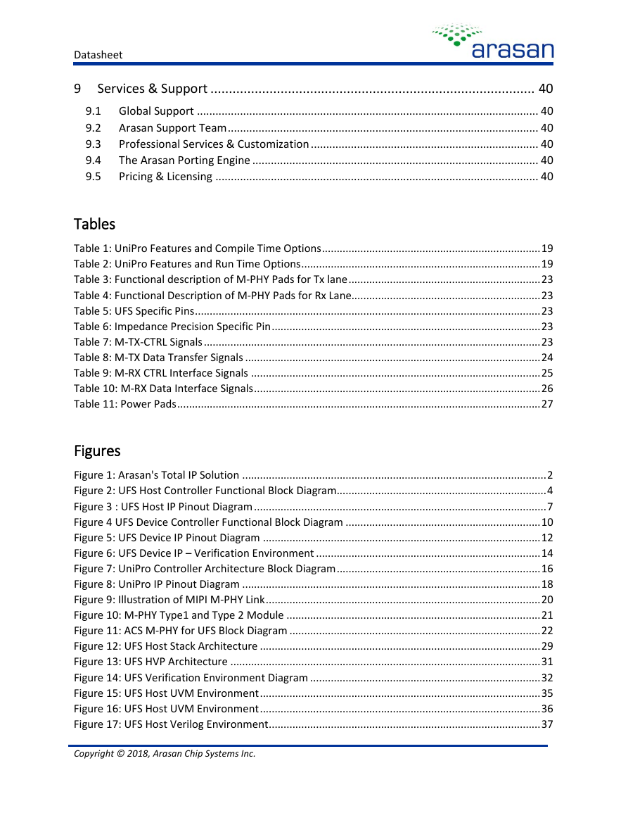
Datasheet 9 Services & Support ........................................................................................ 40 9.1 Global Support ............................................................................................................... 40 9.2 Arasan Support Team ..................................................................................................... 40 Professional Services & Customization .......................................................................... 40 9.3 The Arasan Porting Engine ............................................................................................. 40 9.4 9.5 Pricing & Licensing ......................................................................................................... 40 Tables Table 1: UniPro Features and Compile Time Options Table 2: UniPro Features and Run Time Options Table 3: Functional description of M-PHY Pads for Tx lane Table 4: Functional Description of M-PHY Pads for Rx Lane Table 5: UFS Specific Pins Table 6: Impedance Precision Specific Pin Table 7: M-TX-CTRL Signals Table 8: M-TX Data Transfer Signals Table 9: M-RX CTRL Interface Signals Table 10: M-RX Data Interface Signals Table 11: Power Pads .......................................................................... 19 ................................................................................. 19 ................................................................. 23 ................................................................ 23 ..................................................................................................................... 23 ........................................................................................... 23 .................................................................................................................. 23 .................................................................................................... 24 .................................................................................................. 25 ................................................................................................. 26 ........................................................................................................................... 27 Figures Figure 1: Arasan's Total IP Solution Figure 2: UFS Host Controller Functional Block Diagram Figure 3 : UFS Host IP Pinout Diagram Figure 4 UFS Device Controller Functional Block Diagram Figure 5: UFS Device IP Pinout Diagram Figure 6: UFS Device IP – Verification Environment Figure 7: UniPro Controller Architecture Block Diagram Figure 8: UniPro IP Pinout Diagram Figure 9: Illustration of MIPI M-PHY Link Figure 10: M-PHY Type1 and Type 2 Module Figure 11: ACS M-PHY for UFS Block Diagram Figure 12: UFS Host Stack Architecture Figure 13: UFS HVP Architecture Figure 14: UFS Verification Environment Diagram Figure 15: UFS Host UVM Environment Figure 16: UFS Host UVM Environment Figure 17: UFS Host Verilog Environment ....................................................................................................... 2 ....................................................................... 4 ................................................................................................... 7 .................................................................. 10 .............................................................................................. 12 ............................................................................ 14 ..................................................................... 16 ..................................................................................................... 18 ............................................................................................. 20 ...................................................................................... 21 ..................................................................................... 22 ............................................................................................... 29 ......................................................................................................... 31 .............................................................................. 32 ............................................................................................... 35 ............................................................................................... 36 ............................................................................................ 37 Copyright © 2018, Arasan Chip Systems Inc.
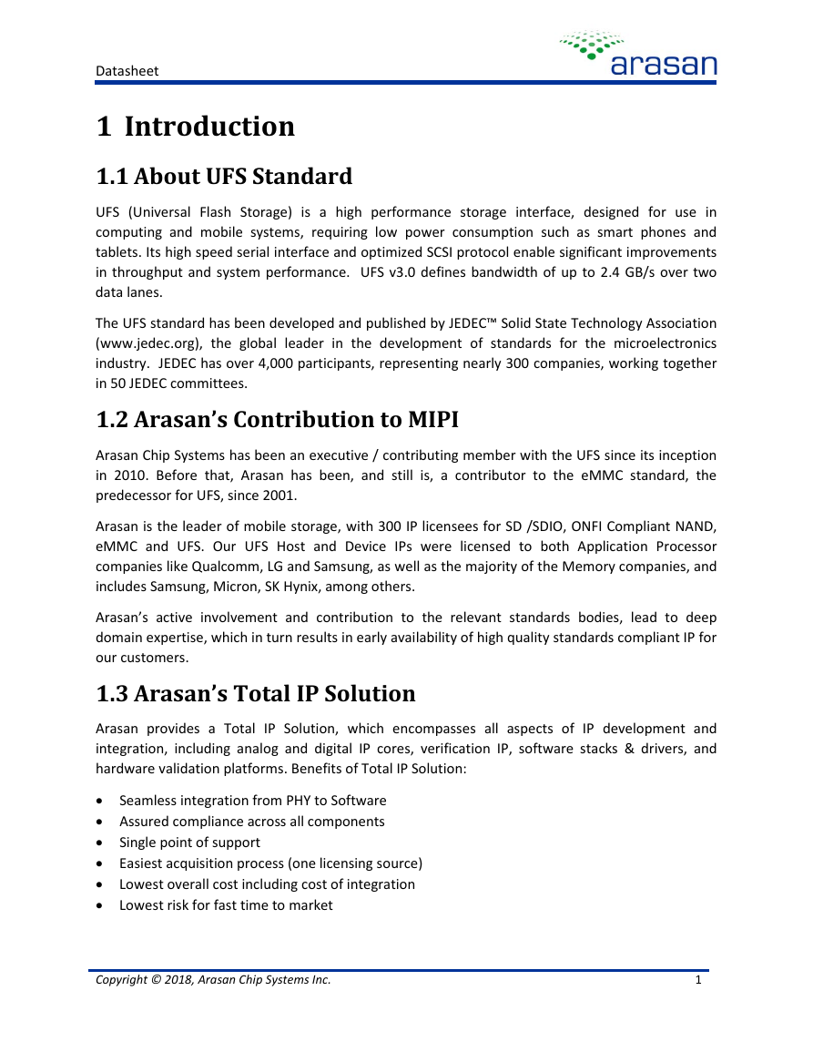
Datasheet 1 Introduction 1.1 About UFS Standard UFS (Universal Flash Storage) is a high performance storage interface, designed for use in computing and mobile systems, requiring low power consumption such as smart phones and tablets. Its high speed serial interface and optimized SCSI protocol enable significant improvements in throughput and system performance. UFS v3.0 defines bandwidth of up to 2.4 GB/s over two data lanes. The UFS standard has been developed and published by JEDEC™ Solid State Technology Association (www.jedec.org), the global leader in the development of standards for the microelectronics industry. JEDEC has over 4,000 participants, representing nearly 300 companies, working together in 50 JEDEC committees. 1.2 Arasan’s Contribution to MIPI Arasan Chip Systems has been an executive / contributing member with the UFS since its inception in 2010. Before that, Arasan has been, and still is, a contributor to the eMMC standard, the predecessor for UFS, since 2001. Arasan is the leader of mobile storage, with 300 IP licensees for SD /SDIO, ONFI Compliant NAND, eMMC and UFS. Our UFS Host and Device IPs were licensed to both Application Processor companies like Qualcomm, LG and Samsung, as well as the majority of the Memory companies, and includes Samsung, Micron, SK Hynix, among others. Arasan’s active involvement and contribution to the relevant standards bodies, lead to deep domain expertise, which in turn results in early availability of high quality standards compliant IP for our customers. 1.3 Arasan’s Total IP Solution Arasan provides a Total IP Solution, which encompasses all aspects of IP development and integration, including analog and digital IP cores, verification IP, software stacks & drivers, and hardware validation platforms. Benefits of Total IP Solution: • Seamless integration from PHY to Software • Assured compliance across all components • Single point of support • Easiest acquisition process (one licensing source) • Lowest overall cost including cost of integration • Lowest risk for fast time to market Copyright © 2018, Arasan Chip Systems Inc. 1
Datasheet Figure 1: Arasan's Total IP Solution Copyright © 2018, Arasan Chip Systems Inc. 2
Datasheet 2 UFS 3.0 Host IP 2.1 Overview Universal Flash Storage (UFS) is a JEDEC standard for high performance mobile storage devices suitable for next generation data storage. UFS is also adopted by Mobile Industry Processor Interface (MIPI) as a data transfer standard designed for mobile systems. UFS incorporates the MIPI UniPro standard as well as the MIPI Alliance M-PHY standard. Most UFS applications require large storage capacity for data and boot code. Applications include mobile phones, tablets, Digital Still Camera (DSC), Portable Media Player (PMP), MP3, and other applications requiring mass storage, boot storage, XIP or external cards. The UFS standard is a simple but high-performance serial interface that efficiently moves data between a host processor and mass storage devices. USF transfers follow the SCSI model, but with a subset of Small Computer System Interface (SCSI) commands. The Arasan UFS IP family consists of Host controller IP, Device controller IP, and M-PHY. The UFS compliant IP cores are interface building blocks that simplify interconnect architectures in mobile platforms. This leads to smaller footprint, greater interoperability between mobile IP, chips and devices from diverse sources, and lower power and Electro Magnetic Interface (EMI). Arasan’s UFS Host Controller IP, described in this document, is designed for ease of integration, highest interoperability, and fully compliant to the JEDEC standards. It is implemented based on Arasan’s proven MIPI technology, including UniPro and M-PHY. The UFS 3.0 specification adds HS-GEAR3 and HS-GEAR4 as mandatory. The UniPro 1.8 specification adds new attributes and modified some of the existing attributes for each layer. 2.2 Features • Compliant with the following specification versions: JESD220D.pdf JESD223D.pdf    MIPI UniPro version 1.8  MIPI M-PHY version 4.1 • Interfaces Supported:  AXI Bus Protocol (AXI)  Advanced High Performance Bus (AHB), Open Core Protocol (OCP) (Optional)  High-performance M-PHY type 1 • Core Features:  Two Lanes  Low power with multiple power operating modes  Configurable Transmit and Receive First In First Out (FIFO)s Copyright © 2018, Arasan Chip Systems Inc. 3
分享到:
收藏