logo资料库

智能割草机专用标准,iec60335-2-107{ed1.0}2012.pdf

第1页 / 共148页
第2页 / 共148页
第3页 / 共148页
第4页 / 共148页
第5页 / 共148页
第6页 / 共148页
第7页 / 共148页
第8页 / 共148页
资料共148页,剩余部分请下载后查看
English
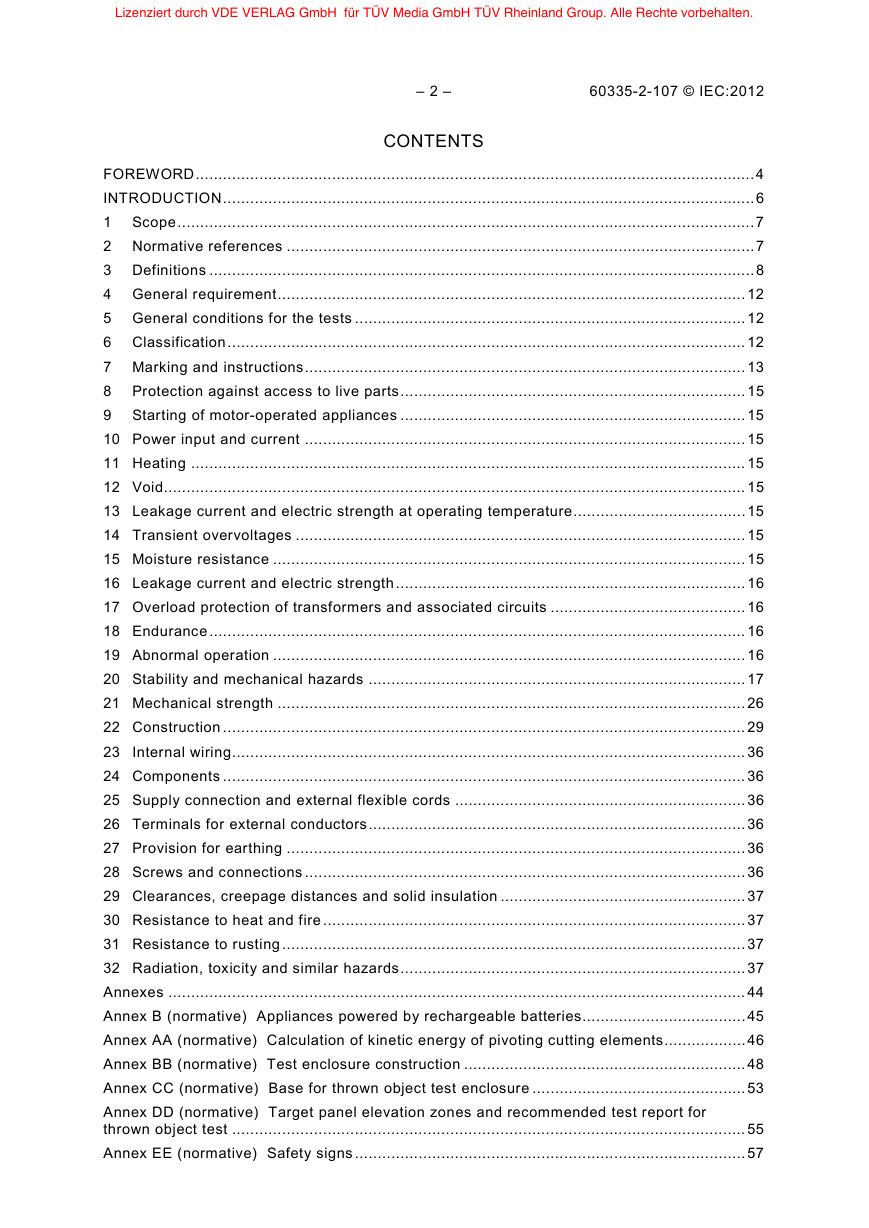
CONTENTS
FOREWORD
INTRODUCTION
1 Scope
2 Normative references
3 Definitions
4 General requirement
5 General conditions for the tests
6 Classification
7 Marking and instructions
8 Protection against access to live parts
9 Starting of motoroperated appliances
10 Power input and current
11 Heating
12 Void
13 Leakage current and electric strength at operating temperature
14 Transient overvoltages
15 Moisture resistance
16 Leakage current and electric strength
17 Overload protection of transformers and associated circuits
18 Endurance
19 Abnormal operation
20 Stability and mechanical hazards
21 Mechanical strength
22 Construction
23 Internal wiring
24 Components
25 Supply connection and external flexible cords
26 Terminals for external conductors
27 Provision for earthing
28 Screws and connections
29 Clearances, creepage distances and solid insulation
30 Resistance to heat and fire
31 Resistance to rusting
32 Radiation, toxicity and similar hazards
Annexes
Annex B (normative) Appliances powered by rechargeable batteries
Annex AA (normative) Calculation of kinetic energy of pivoting cutting elements
Annex BB (normative) Test enclosure construction
Annex CC (normative) Base for thrown object test enclosure
Annex DD (normative) Target panel elevation zones and recommended test report for thrown object test
Annex EE (normative) Safety signs
Annex FF (normative) Noise test code – Engineering method (grade 2)
Annex GG (informative) Example of a material and construction fulfilling the requirements for an artificial surface
Annex HH (informative) Safety instructions
Bibliography
Figures
Figure 101 – Example of test cycles (see 20.102.2)
Figure 102 – Foot probe test (see 20.102.4)
Figure 103 – Impact test fixture (see 21.101.1)
Figure 104 – Example of structural integrity test fixtures (see 21.101.3.1.1)
Figure 105 – Finger probe test – Illustrations showing application of probe, insertion depth limited according to the geometry of the enclosure
Figure 106 – Obstruction sensor test – Illustration showing typical arrangement(see 22.105.2)
Figure AA.1 – Measurement of the reckonable length L
Figure BB.1 – Thrown object test enclosure – General layout
Figure BB.2 – Thrown object test enclosure
Figure BB.3 – Test enclosure walls and base
Figure BB.4 – Test fixture for corrugated fibreboard penetration test
Figure CC.1 – Thrown object test enclosure – Base detail
Figure CC.2 – Nail plan of test enclosure base
Figure DD.1 – Recommended test data sheet
Figure EE.1 – Safety sign illustrating – "WARNING –Read user instructions before operating the machine"
Figure EE.2 – Alternative safety sign for the supplementary safety information panel of EE.1 (safety sign 1641 of ISO 7000)
Figure EE.3 – Alternative safety sign for the supplementary safety information panel of EE.1 (safety sign M002 of ISO 7010)
Figure EE.4 – Safety sign illustrating – "WARNING – Keep a safe distance from the machine when operating"
Figure EE.5 – Safety sign illustrating – "WARNING – Remove the disabling device before working on or lifting the machine"
Figure EE.6 – Safety sign illustrating – "WARNING – Operate the disabling device before working on or lifting the machine"
Figure EE.7 – Safety sign illustrating – "WARNING – Do not ride on the machine"
Figure FF.1 – Microphone positions on the hemisphere (see Table FF.1)
Figure GG.1 – Sketch of the measurement surface covered with an artificial surface (not to scale)
Tables
Table 1 – Sizing of test fixture air inlet holes
Table FF.1 – Co-ordinates of microphone positions
Table FF.2 – Absorption coefficients
Français
SOMMAIRE
AVANT-PROPOS
INTRODUCTION
1 Domaine d’application
2 Références normatives
3 Définitions
4 Exigences générales
5 Conditions générales d’essais
6 Classification
7 Marquage et instructions
8 Protection contre l’accès aux parties actives
9 Démarrage des appareils à moteur
10 Puissance et courant
11 Echauffements
12 Vacant
13 Courant de fuite et rigidité diélectrique à la température de régime
14 Surtensions transitoires
15 Résistance à l’humidité
16 Courant de fuite et rigidité diélectrique
17 Protection contre la surcharge des transformateurs et des circuits associés
18 Endurance
19 Fonctionnement anormal
20 Stabilité et dangers mécaniques
21 Résistance mécanique
22 Construction
23 Conducteurs internes
24 Composants
25 Raccordement au réseau et câbles souples extérieurs
26 Bornes pour conducteurs externes
27 Dispositions en vue de la mise en terre
28 Vis et connexions
29 Distances dans l’air, lignes de fuite et isolation solide
30 Résistance à la chaleur et au feu
31 Protection contre la rouille
32 Rayonnement, toxicité et dangers analogues
Annexes
Annexe B (normative) Appareils alimentés par batteries
Annexe AA (normative) Calcul de l’énergie cinétique des éléments de coupe pivotants
Annexe BB (normative) Construction de l’enceinte d’essai
Annexe CC (normative) Support pour l’enceinte d’essai de projection d’objets
Annexe DD (normative) Zones de hauteur des panneaux cibles et rapport d’essai recommandé pour l’essai de projection d’objets
Annexe EE (normative) Signaux de sécurité
Annexe FF (normative) Code d’essai acoustique – Méthode d’expertise (degré d’exactitude 2)
Annexe GG (informative) Exemple de matériau et de construction satisfaisant aux exigences relatives à une surface artificielle
Annexe HH (informative) Consignes de sécurité
Bibliographie
Figures
Figure 101 – Exemple de cycles d’essai (voir 20.102.2)
Figure 102 – Essai au pied d’essai (voir 20.102.4)
Figure 103 – Dispositif de l’essai d’impact (voir 21.101.1)
Figure 104 – Exemple de dispositif d’essai d'intégrité structurelle (voir 21.101.3.1.1)
Figure 105 – Essai au doigt d’essai – Illustrations indiquant l’application du calibre d’essai, la limitation de la profondeur d’introduction selon la géométrie de l’enceinte
Figure 106 – Essai au capteur de détection d’obstacles – Illustration indiquantune disposition type (voir 22.105.2)
Figure AA.1 – Mesure de la longueur de référence L
Figure BB.1 – Enceinte d’essai pour la projection d’objets – Disposition générale
Figure BB.2 – Enceinte d’essai pour la projection d’objets
Figure BB.3 – Parois et support de l’enceinte d’essai
Figure BB.4 – Dispositif pour l’essai de pénétration du carton ondulé
Figure CC.1 – Enceinte d’essai pour la projection d’objets – Détail du support
Figure CC.2 – Plan de clouage du support de l’enceinte d’essai
Figure DD.1 – Fiche technique d’essai recommandée
Figure EE.1 – Représentation du signal de sécurité – «MISE EN GARDE – Lire les instructions d’utilisation avant de faire fonctionner la machine»
Figure EE.2 – Signal alternatif de sécurité pour un panneau supplémentaire d'information de sécurité du EE.1 (signal de sécurité 1641 de l’ISO 7000)
Figure EE.3 – Signal alternatif de sécurité pour un panneau supplémentaire d'information de sécurité du EE.1 (signal de sécurité M002 de l’ISO 7010)
Figure EE.4 – Représentation du signal de sécurité – «MISE EN GARDE – Maintenir une distance de sécurité avec la machine en fonctionnement»
Figure EE.5 – Représentation du signal de sécurité – «MISE EN GARDE – Retirer le dispositif de mise hors fonctionnement avant d’effectuer tout travail sur la machine ou avant de la soulever»
Figure EE.6 – Représentation du signal de sécurité – «MISE EN GARDE – Faire fonctionner le dispositif de mise hors fonctionnement avant d’effectuer tout travail sur la machine ou avant de la soulever»
Figure EE.7 – Représentation du signal de sécurité – «MISE EN GARDE –Ne pas monter sur la machine»
Figure FF.1 – Positions des microphones sur l’hémisphère (voir Tableau FF.1)
Figure GG.1 – Croquis de la surface de mesure recouverted’une surface artificielle (non à l’échelle)
Tableaux
Tableau 1 – Dimensions des orifices d’entrée d’air du dispositif d’essai
Tableau FF.1 – Coordonnées des positions de microphones
Tableau FF.2 – Coefficients d’absorption
Lizenziert durch VDE VERLAG GmbH für TÜV Media GmbH TÜV Rheinland Group. Alle Rechte vorbehalten. IEC 60335-2-107 Edition 1.0 2012-02 ® INTERNATIONAL STANDARD NORME INTERNATIONALE Household and similar electrical appliances – Safety – Part 2-107: Particular requirements for robotic battery powered electrical lawnmowers Appareils électrodomestiques et analogues – Sécurité – Partie 2-107: Exigences particulières relatives aux tondeuses à gazon électriques robotisées alimentées par batterie 2 1 0 2 : 7 0 1 - 2 - 5 3 3 0 6 C E I 3 8 9 1 7 6 0 3 colourinside
Lizenziert durch VDE VERLAG GmbH für TÜV Media GmbH TÜV Rheinland Group. Alle Rechte vorbehalten. THIS PUBLICATION IS COPYRIGHT PROTECTED Copyright © 2012 IEC, Geneva, Switzerland All rights reserved. Unless otherwise specified, no part of this publication may be reproduced or utilized in any form or by any means, electronic or mechanical, including photocopying and microfilm, without permission in writing from either IEC or IEC's member National Committee in the country of the requester. If you have any questions about IEC copyright or have an enquiry about obtaining additional rights to this publication, please contact the address below or your local IEC member National Committee for further information. Droits de reproduction réservés. Sauf indication contraire, aucune partie de cette publication ne peut être reproduite ni utilisée sous quelque forme que ce soit et par aucun procédé, électronique ou mécanique, y compris la photocopie et les microfilms, sans l'accord écrit de la CEI ou du Comité national de la CEI du pays du demandeur. Si vous avez des questions sur le copyright de la CEI ou si vous désirez obtenir des droits supplémentaires sur cette publication, utilisez les coordonnées ci-après ou contactez le Comité national de la CEI de votre pays de résidence. IEC Central Office 3, rue de Varembé CH-1211 Geneva 20 Switzerland Tel.: +41 22 919 02 11 Fax: +41 22 919 03 00 info@iec.ch www.iec.ch About the IEC The International Electrotechnical Commission (IEC) is the leading global organization that prepares and publishes International Standards for all electrical, electronic and related technologies. About IEC publications The technical content of IEC publications is kept under constant review by the IEC. Please make sure that you have the latest edition, a corrigenda or an amendment might have been published. Useful links: IEC publications search - www.iec.ch/searchpub The advanced search enables you to find IEC publications by a variety of criteria (reference number, text, technical committee,…). It also gives withdrawn publications. IEC Just Published - webstore.iec.ch/justpublished Stay up to date on all new IEC publications. Just Published details all new publications released. Available on-line and also once a month by email. Electropedia - www.electropedia.org The world's leading online dictionary of electronic and electrical terms containing more than 30 000 terms and definitions in English and French, with equivalent terms in additional languages. Also known as the International Electrotechnical Vocabulary (IEV) on-line. Customer Service Centre - webstore.iec.ch/csc If you wish to give us your feedback on this publication or need the Customer Service Centre: csc@iec.ch. information on projects, replaced and further assistance, please contact A propos de la CEI La Commission Electrotechnique Internationale (CEI) est la première organisation mondiale qui élabore et publie des Normes internationales pour tout ce qui a trait à l'électricité, à l'électronique et aux technologies apparentées. A propos des publications CEI Le contenu technique des publications de la CEI est constamment revu. Veuillez vous assurer que vous possédez l’édition la plus récente, un corrigendum ou amendement peut avoir été publié. Liens utiles: Recherche de publications CEI - www.iec.ch/searchpub La recherche avancée vous permet de trouver des publications CEI en utilisant différents critères (numéro de référence, texte, comité d’études,…). Elle donne aussi des informations sur les projets et les publications remplacées ou retirées. Just Published CEI - webstore.iec.ch/justpublished Restez informé sur les nouvelles publications de la CEI. Just Published détaille les nouvelles publications parues. Disponible en ligne et aussi une fois par mois par email. Electropedia - www.electropedia.org Le premier dictionnaire en ligne au monde de termes électroniques et électriques. Il contient plus de 30 000 termes et définitions en anglais et en français, ainsi que les termes équivalents dans les langues additionnelles. Egalement Electrotechnique International (VEI) en ligne. Service Clients - webstore.iec.ch/csc Si vous désirez nous donner des commentaires sur cette publication ou si vous avez des questions contactez-nous: csc@iec.ch. Vocabulaire appelé 3 8 9 1 7 6 0 3
Lizenziert durch VDE VERLAG GmbH für TÜV Media GmbH TÜV Rheinland Group. Alle Rechte vorbehalten. IEC 60335-2-107 Edition 1.0 2012-02 ® INTERNATIONAL STANDARD NORME INTERNATIONALE Household and similar electrical appliances – Safety – Part 2-107: Particular requirements for robotic battery powered electrical lawnmowers Appareils électrodomestiques et analogues – Sécurité – Partie 2-107: Exigences particulières relatives aux tondeuses à gazon électriques robotisées alimentées par batterie INTERNATIONAL ELECTROTECHNICAL COMMISSION COMMISSION ELECTROTECHNIQUE INTERNATIONALE ICS 65.060.70 PRICE CODE CODE PRIX XB ISBN 978-2-88912-895-2 Warning! Make sure that you obtained this publication from an authorized distributor. Attention! Veuillez vous assurer que vous avez obtenu cette publication via un distributeur agréé. ® Registered trademark of the International Electrotechnical Commission Marque déposée de la Commission Electrotechnique Internationale 3 8 9 1 7 6 0 3 colourinside
Lizenziert durch VDE VERLAG GmbH für TÜV Media GmbH TÜV Rheinland Group. Alle Rechte vorbehalten. – 2 – 60335-2-107 © IEC:2012 CONTENTS FOREWORD ........................................................................................................................... 4 INTRODUCTION ..................................................................................................................... 6 1 Scope ............................................................................................................................... 7 2 Normative references ....................................................................................................... 7 3 Definitions ........................................................................................................................ 8 4 General requirement ....................................................................................................... 12 5 General conditions for the tests ...................................................................................... 12 6 Classification .................................................................................................................. 12 7 Marking and instructions ................................................................................................. 13 8 Protection against access to live parts ............................................................................ 15 9 Starting of motor-operated appliances ............................................................................ 15 10 Power input and current ................................................................................................. 15 11 Heating .......................................................................................................................... 15 12 Void................................................................................................................................ 15 13 Leakage current and electric strength at operating temperature ...................................... 15 14 Transient overvoltages ................................................................................................... 15 15 Moisture resistance ........................................................................................................ 15 16 Leakage current and electric strength ............................................................................. 16 17 Overload protection of transformers and associated circuits ........................................... 16 18 Endurance ...................................................................................................................... 16 19 Abnormal operation ........................................................................................................ 16 20 Stability and mechanical hazards ................................................................................... 17 21 Mechanical strength ....................................................................................................... 26 22 Construction ................................................................................................................... 29 23 Internal wiring ................................................................................................................. 36 24 Components ................................................................................................................... 36 25 Supply connection and external flexible cords ................................................................ 36 26 Terminals for external conductors ................................................................................... 36 27 Provision for earthing ..................................................................................................... 36 28 Screws and connections ................................................................................................. 36 29 Clearances, creepage distances and solid insulation ...................................................... 37 30 Resistance to heat and fire ............................................................................................. 37 31 Resistance to rusting ...................................................................................................... 37 32 Radiation, toxicity and similar hazards ............................................................................ 37 Annexes ............................................................................................................................... 44 Annex B (normative) Appliances powered by rechargeable batteries.................................... 45 Annex AA (normative) Calculation of kinetic energy of pivoting cutting elements .................. 46 Annex BB (normative) Test enclosure construction .............................................................. 48 Annex CC (normative) Base for thrown object test enclosure ............................................... 53 Annex DD (normative) Target panel elevation zones and recommended test report for thrown object test ................................................................................................................. 55 Annex EE (normative) Safety signs ...................................................................................... 57 3 8 9 1 7 6 0 3
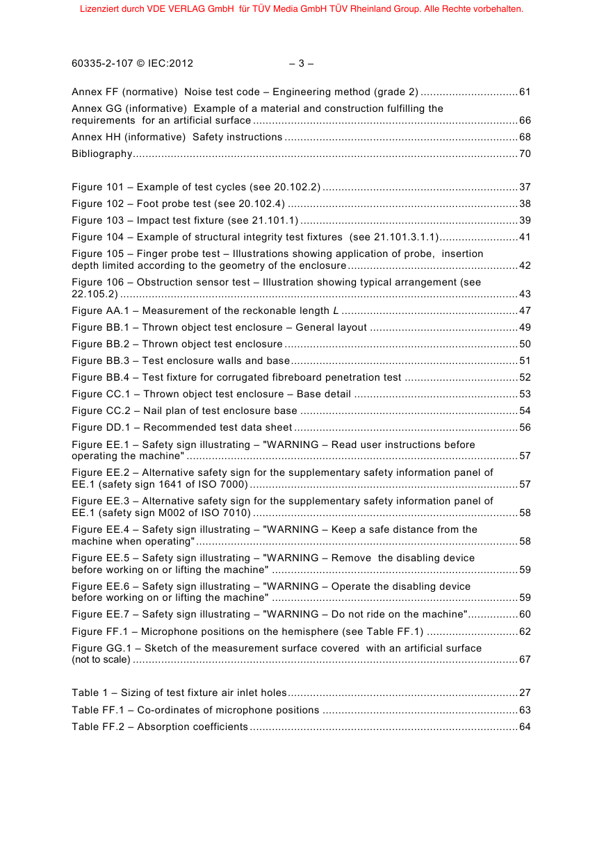
Lizenziert durch VDE VERLAG GmbH für TÜV Media GmbH TÜV Rheinland Group. Alle Rechte vorbehalten. 60335-2-107 © IEC:2012 – 3 – Annex FF (normative) Noise test code – Engineering method (grade 2) ............................... 61 Annex GG (informative) Example of a material and construction fulfilling the requirements for an artificial surface .................................................................................... 66 Annex HH (informative) Safety instructions .......................................................................... 68 Bibliography .......................................................................................................................... 70 Figure 101 – Example of test cycles (see 20.102.2) .............................................................. 37 Figure 102 – Foot probe test (see 20.102.4) ......................................................................... 38 Figure 103 – Impact test fixture (see 21.101.1) ..................................................................... 39 Figure 104 – Example of structural integrity test fixtures (see 21.101.3.1.1) ......................... 41 Figure 105 – Finger probe test – Illustrations showing application of probe, insertion depth limited according to the geometry of the enclosure ...................................................... 42 Figure 106 – Obstruction sensor test – Illustration showing typical arrangement (see 22.105.2) .............................................................................................................................. 43 Figure AA.1 – Measurement of the reckonable length L ........................................................ 47 Figure BB.1 – Thrown object test enclosure – General layout ............................................... 49 Figure BB.2 – Thrown object test enclosure .......................................................................... 50 Figure BB.3 – Test enclosure walls and base ........................................................................ 51 Figure BB.4 – Test fixture for corrugated fibreboard penetration test .................................... 52 Figure CC.1 – Thrown object test enclosure – Base detail .................................................... 53 Figure CC.2 – Nail plan of test enclosure base ..................................................................... 54 Figure DD.1 – Recommended test data sheet ....................................................................... 56 Figure EE.1 – Safety sign illustrating – "WARNING – Read user instructions before operating the machine" ......................................................................................................... 57 Figure EE.2 – Alternative safety sign for the supplementary safety information panel of EE.1 (safety sign 1641 of ISO 7000) ..................................................................................... 57 Figure EE.3 – Alternative safety sign for the supplementary safety information panel of EE.1 (safety sign M002 of ISO 7010) .................................................................................... 58 Figure EE.4 – Safety sign illustrating – "WARNING – Keep a safe distance from the machine when operating" ...................................................................................................... 58 Figure EE.5 – Safety sign illustrating – "WARNING – Remove the disabling device before working on or lifting the machine" .............................................................................. 59 Figure EE.6 – Safety sign illustrating – "WARNING – Operate the disabling device before working on or lifting the machine" .............................................................................. 59 Figure EE.7 – Safety sign illustrating – "WARNING – Do not ride on the machine" ................ 60 Figure FF.1 – Microphone positions on the hemisphere (see Table FF.1) ............................. 62 Figure GG.1 – Sketch of the measurement surface covered with an artificial surface (not to scale) .......................................................................................................................... 67 Table 1 – Sizing of test fixture air inlet holes ......................................................................... 27 Table FF.1 – Co-ordinates of microphone positions .............................................................. 63 Table FF.2 – Absorption coefficients ..................................................................................... 64 3 8 9 1 7 6 0 3
Lizenziert durch VDE VERLAG GmbH für TÜV Media GmbH TÜV Rheinland Group. Alle Rechte vorbehalten. – 4 – 60335-2-107 © IEC:2012 INTERNATIONAL ELECTROTECHNICAL COMMISSION ____________ HOUSEHOLD AND SIMILAR ELECTRICAL APPLIANCES – Part 2-107: Particular requirements for robotic battery powered electrical lawnmowers SAFETY – FOREWORD 1) The International Electrotechnical Commission (IEC) is a worldwide organization for standardization comprising all national electrotechnical committees (IEC National Committees). The object of IEC is to promote international co-operation on all questions concerning standardization in the electrical and electronic fields. To this end and in addition to other activities, IEC publishes International Standards, Technical Specifications, Technical Reports, Publicly Available Specifications (PAS) and Guides (hereafter referred to as “IEC Publication(s)”). Their preparation is entrusted to technical committees; any IEC National Committee interested in the subject dealt with may participate in this preparatory work. International, governmental and non- governmental organizations liaising with the IEC also participate in this preparation. IEC collaborates closely with the International Organization for Standardization (ISO) in accordance with conditions determined by agreement between the two organizations. 2) The formal decisions or agreements of IEC on technical matters express, as nearly as possible, an international consensus of opinion on the relevant subjects since each technical committee has representation from all interested IEC National Committees. 3) IEC Publications have the form of recommendations for international use and are accepted by IEC National Committees in that sense. While all reasonable efforts are made to ensure that the technical content of IEC Publications is accurate, IEC cannot be held responsible for the way in which they are used or for any misinterpretation by any end user. 4) In order to promote international uniformity, IEC National Committees undertake to apply IEC Publications transparently to the maximum extent possible in their national and regional publications. Any divergence between any IEC Publication and the corresponding national or regional publication shall be clearly indicated in the latter. 5) IEC itself does not provide any attestation of conformity. Independent certification bodies provide conformity assessment services and, in some areas, access to IEC marks of conformity. IEC is not responsible for any services carried out by independent certification bodies. 6) All users should ensure that they have the latest edition of this publication. 7) No liability shall attach to IEC or its directors, employees, servants or agents including individual experts and members of its technical committees and IEC National Committees for any personal injury, property damage or other damage of any nature whatsoever, whether direct or indirect, or for costs (including legal fees) and expenses arising out of the publication, use of, or reliance upon, this IEC Publication or any other IEC Publications. 8) Attention is drawn to the Normative references cited in this publication. Use of the referenced publications is indispensable for the correct application of this publication. 9) Attention is drawn to the possibility that some of the elements of this IEC Publication may be the subject of patent rights. IEC shall not be held responsible for identifying any or all such patent rights. International Standard IEC 60335-2-107 has been prepared IEC technical committee 116: Safety of motor-operated electric tools. The text of this standard is based on the following documents: FDIS 116/79/FDIS Report on voting 116/86/RVD Full information on the voting for the approval of this standard can be found in the report on voting indicated in the above table. This publication has been drafted in accordance with the ISO/IEC Directives, Part 2. 3 8 9 1 7 6 0 3
Lizenziert durch VDE VERLAG GmbH für TÜV Media GmbH TÜV Rheinland Group. Alle Rechte vorbehalten. 60335-2-107 © IEC:2012 – 5 – This part 2 is to be used in conjunction with the fourth edition (2001) of IEC 60335-1 and its amendments. NOTE 1 When “Part 1” is mentioned in this standard, it refers to IEC 60335-1. This part 2 supplements or modifies the corresponding clauses in IEC 60335-1, so as to convert that publication into the IEC standard: Safety requirements for robotic battery powered electrical lawnmowers. When a particular subclause of Part 1 is not mentioned in this part 2, that subclause applies as far as is reasonable. When this standard states “addition”, “modification” or “replacement”, the relevant text in Part 1 is to be adapted accordingly. NOTE 2 The following numbering system is used: – subclauses, tables and figures that are numbered starting from 101 are additional to those in Part 1; – unless notes are in a new subclause or involve notes in Part 1, they are numbered starting from 101, including those in a replaced clause or subclause; – additional annexes are lettered AA, BB, etc. NOTE 3 The following print types are used: – Requirements: in roman type – Test specification: in italic type – Notes: in small roman type Words in bold in the text are defined in clause 3. When a definition concerns an adjective, the adjective and the associated noun are also in bold. A list of all parts of the IEC 60335 series, under the general title: Household and similar electrical appliances – Safety, can be found on the IEC website. The committee has decided that the contents of this publication will remain unchanged until the stability date indicated on the IEC web site under "http://webstore.iec.ch" in the data related to the specific publication. At this date, the publication will be reconfirmed, replaced by a revised edition, or • • withdrawn, • • amended. IMPORTANT – The 'colour inside' logo on the cover page of this publication indicates the correct that understanding of its contents. Users should therefore print this document using a colour printer. it contains colours which are considered to be useful for 3 8 9 1 7 6 0 3
Lizenziert durch VDE VERLAG GmbH für TÜV Media GmbH TÜV Rheinland Group. Alle Rechte vorbehalten. – 6 – 60335-2-107 © IEC:2012 INTRODUCTION It has been assumed in the drafting of this International Standard that the execution of its provisions is entrusted to appropriately qualified and experienced persons. This standard recognizes the internationally accepted level of protection against hazards such as electrical, mechanical, thermal, fire and radiation of machines when operated as in normal use taking into account the manufacturer's instructions. It also covers abnormal situations that can be expected in practice and takes into account the way in which electromagnetic phenomena can affect the safe operation of machines. This standard takes into account the requirements of IEC 60364 as far as possible so that there is compatibility with the wiring rules when the machine is connected to the supply mains. However, national wiring rules may differ. If a machine within the scope of this standard also incorporates functions that are covered by another part 2 of IEC 60335, the relevant part 2 is applied to each function separately, as far as is reasonable. If applicable, the influence of one function on the other is taken into account. When a part 2 standard does not include additional requirements to cover hazards dealt with in Part 1, Part 1 applies. NOTE 1 This means that the technical committees responsible for the part 2 standards have determined that it is not necessary to specify particular requirements for the machine in question over and above the general requirements. This standard is a product family standard dealing with the safety of appliances and takes precedence over horizontal and generic standards covering the same subject. NOTE 2 Horizontal and generic standards covering a hazard are not applicable since they have been taken into consideration when developing the general and particular requirements for the IEC 60335 series of standards. For example, in the case of temperature requirements for surfaces on many appliances, generic standards, such as ISO 13732-1 for hot surfaces, are not applicable in addition to Part 1 or part 2 standards. A machine that complies with the text of this standard will not necessarily be considered to comply with the safety principles of the standard if, when examined and tested, it is found to have other features that impair the level of safety covered by these requirements. A machine employing materials or having forms of construction differing from those detailed in the requirements of this standard may be examined and tested according to the intent of the requirements and, if found to be substantially equivalent, may be considered to comply with the standard. The non-electrical safety requirements covering non-electrical hazards have been taken from IEC 60335-2-77 where appropriate. 3 8 9 1 7 6 0 3
分享到:
收藏