RN6752M
1-Channel HD Video Decoder with MIPI CSI2 Output
RN6752M
Data Sheet
1-Channel HD Video Decoder
With
MIPI CSI2 Output
(Rev. 0.3)
RICHNEX CONFIDENTIAL AND PROPRIETARY
RICHNEX MICROELECTRONICS CORP.
4F, No.95, Minchiuan Road, Hsintien District,
New Taipei City, Taiwan 23145
T 886-2-86676161
F 886-2-86673131
www.richnex.com
Rev. 0.3 – July.2018 Richnex Confidential and Proprietary Page 1 of 44
�
RN6752M
1-Channel HD Video Decoder with MIPI CSI2 Output
Revision History
Revision
Date
Notes
0.1
0.2
0.3
2018-06-27
Initial draft.
2018-07-24
Added register FEh product ID description
2018-07-25
Added register 19h description.
Copyright © 2010-2018 by Richnex Microelectronics Corp.
NOTE:
Richnex reserves the right to change the circuitry and/or specifications without notice at any time. Customers
should obtain the latest relevant information and data sheets before placing orders and should verify that such
information is current and complete. Richnex cannot assume responsibility for use of any circuitry other than
circuitry entirely embodied in a Richnex product. Information furnished by Richnex is believed to be accurate and
reliable. However, no responsibility is assumed by Richnex or its subsidiaries for its use; nor for any
infringements of patents or other rights of third parties which may result from its use. No license is granted by
implication or otherwise under any patent or patent rights of Richnex or its subsidiaries.
Rev. 0.3 – July.2018 Richnex Confidential and Proprietary Page 2 of 44
�
RN6752M
1-Channel HD Video Decoder with MIPI CSI2 Output
TABLE OF CONTENTS ......................................................................................................... 3
Table of Contents
1
2
3
4
5
6
7
8
GENERAL DESCRIPTION .............................................................................................. 5
CONTACT INFORMATION ........................................................................................... 6
FEATURES .................................................................................................................. 7
BLOCK DIAGRAM ....................................................................................................... 8
PIN DIAGRAM ............................................................................................................ 9
PIN DESCRIPTIONS ................................................................................................... 10
I2C ADDRESS SETTING............................................................................................... 12
REGISTER MAP ......................................................................................................... 13
CHIP CONTROL REGISTERS ............................................................................................... 15
8.1.1 Central Control Register........................................................................................... 15
8.1.1.1. Reset / Sleep Control Register .......................................................................... 15
8.1.1.2. Analog Macro Control Register ........................................................................ 15
8.1.2 Video Clock Configuration Register ......................................................................... 15
8.1.2.1. Video Clock Configuration A ............................................................................. 15
8.1.2.2. Video Clock Configuration B ............................................................................. 16
8.1.3 Video Data Port Configuration Register .................................................................. 16
8.1.3.1. Video Data Port Configuration A ...................................................................... 17
8.1.3.2. Video Data Port Configuration B ...................................................................... 17
8.1.3.3. Video Data Port Configuration C ..................................................................... 17
8.1.4 GPIO Pin Configuration Register .............................................................................. 18
8.1.4.1. Video Timing Pin Enable Register ..................................................................... 18
8.1.4.2. Video Timing Pin Direction Control Register .................................................... 19
8.1.4.3. Video Timing Pin GPIO Register ........................................................................ 20
8.1.5 Video ADC MUX Configuration ................................................................................ 21
8.1.6 Video Format Selection Register .............................................................................. 21
8.1.7 Product ID, Low Byte ................................................................................................ 21
8.1.8 Product ID, High Byte ............................................................................................... 21
8.1.9 Register Set Selection .............................................................................................. 22
VIDEO DECODER CONTROL REGISTERS ............................................................................... 22
8.2.1 Mode Control Register ............................................................................................. 22
8.2.2 Brightness Control Register ..................................................................................... 23
8.2.3 Contrast Control Register ........................................................................................ 23
8.2.4 Saturation Control Register ..................................................................................... 23
8.2.5 Hue Control Register ................................................................................................ 23
8.2.6 Enhancement Control Register ................................................................................ 23
8.1
8.2
Rev. 0.3 – July.2018 Richnex Confidential and Proprietary Page 3 of 44
�
RN6752M
1-Channel HD Video Decoder with MIPI CSI2 Output
8.2.7 Input Control Register .............................................................................................. 24
8.2.8 Output & Decoder Control Register ......................................................................... 24
8.2.9 Video Detection Control Register ............................................................................ 24
8.2.10 Blue Screen Control Register.................................................................................. 25
8.2.11 Cropping Control Register...................................................................................... 25
8.2.12 ID Insertion Control Register .................................................................................. 26
8.2.13 BT.656/BT656-like Bus Control Register ................................................................ 30
8.2.14 HD Mode Control Registers ................................................................................... 30
8.2.15 Black/White Stretch Control .................................................................................. 31
8.2.16 Coaxitron Control Registers ................................................................................... 32
8.3 MIPI CONTROL REGISTERS .............................................................................................. 33
8.3.1 MIPI CSI-2 Control Registers .................................................................................... 34
8.3.2 MIPI TX Control Registers ........................................................................................ 36
ELECTRICAL SPECIFICATIONS .................................................................................... 39
9.1
9.2
9.3
9.4
9.5
9.6
ABSOLUTE MAXIMUM RATINGS ........................................................................................ 39
RECOMMENDED OPERATING CONDITIONS .......................................................................... 39
DC CHARACTERISTICS ..................................................................................................... 39
POWER CONSUMPTION ................................................................................................... 40
TWO-WIRE INTERFACE TIMING ......................................................................................... 40
ANALOG VIDEO PARAMETERS .......................................................................................... 40
9
10 APPLICATION DIAGRAM ........................................................................................... 42
11 PACKAGE OUTLINES ................................................................................................. 43
12 ORDERING INFORMATION ....................................................................................... 44
Rev. 0.3 – July.2018 Richnex Confidential and Proprietary Page 4 of 44
�
1 General Description
RN6752M
1-Channel HD Video Decoder with MIPI CSI2 Output
RN6752M is a feature rich, high quality 1-channel HD video decoder chip which integrated 1
ADC. The associated Clamping and automatic gain control (AGC) circuit hold the AC coupled
signal to a DC level as well as set the signal gain for maximum signal dynamic range before
digitization. The analog front-end (AFE) with automatic gain control (AGC) can accept an input
signal and allows signals from the source directly applied to the decoder input without going
through extra gain/attenuation stage. The accurate color carrier phase acquisition is achieved by
the low jitter phase lock loop (PLL).
With an improved and robust sync processing circuit, horizontal and vertical SYNC pulses can be
correctly extracted from a D1, 720p, or 1080p signal. Working together with the AFE, very weak
or noisy video signals can be reliably decoded. Variants of NTSC/PAL signals, 720p or 1080p can
be detected automatically, and a comb filter yields the minimum artifacts in performing Y/C
separation. The video post-processing functions such as color space conversion, brightness,
contrast, saturation, and hue control are independently adjustable for each channel via the I2C
interface.
RN6752M’s video data port is programmable to transmit in the standard ITU-R BT.656 4:2:2
format for D1 resolution video. Higher resolution image, such as 720p or 1080p, can be
transmitted using BT.656-like format. RN6752M also support one MIPI CSI2 output interface.
With a 32-pin, 5mmx5mm QFN package, RN6752M is the best solution for high resolution analog
to digital video conversion applications in terms of functionality, video quality, price, reliability,
and overall customer support. Typical applications of RN6752M include, but not limited to:
standalone security DVR, automobile dash cam and video recorder.
Rev. 0.3 – July.2018 Richnex Confidential and Proprietary Page 5 of 44
�
RN6752M
1-Channel HD Video Decoder with MIPI CSI2 Output
2 Contact Information
Richnex Microelectronics Corporation
4F., No.95, Minchiuan Rd., Hsintien District,
New Taipei City 23145, Taiwan (R.O.C.)
Tel 886-2-8667-6161
Fax 886-2-8667-3131
Email: insidesales@richnex.com
Rev. 0.3 – July.2018 Richnex Confidential and Proprietary Page 6 of 44
�
RN6752M
1-Channel HD Video Decoder with MIPI CSI2 Output
3 Features
Video Decoder
Support MIPI CSI2 differential output
YUV422 output format
1/2/3/4 data lanes per link
Selectable clock and data lanes
Support HD video inputs from 720p and 1080p video sources
Flexible analog video decoder with built-in analog anti-aliasing filter
Automatic detection of NTSC/PAL variants, 720p, and 1080p decoding
High performance ADCs with automatic gain control (AGC) high resolution for
superior picture resolution and sharpness
Proprietary fast and robust video synchronization with accurate clamping and gain
Low jitter PLL for accurate color carrier phase acquisition
Comb filter provides the high quality video decoding of composite video signal for
artifact-free Y/C separation
Brightness/contrast/saturation/hue control, and color correction for best performance
Vertical and horizontal cropping
Selectable 8-bit standard ITU-R BT.656/BT.601/BT656-like YCbCr 4:2:2 format digital
outputs
Increased range and new attenuation option for improved peaking function
Support black/white stretch, and sharpness enhancement post-processing functions
Support programmable TX/RX coaxial communication to control camera operations
control
I2C interface for control and status registers
Only requires a single 27 MHz crystal or clock source on XIN pin directly
Up to 8KV ESD HBM for analog video input pins
Flexible 1.8V to 3.3V I/O interface voltage
Industrial temperature range from -40°C to 85°C available
3.3V and 1.2V power supplies
32pin QFN package (5mm x 5mm)
Miscellaneous
Rev. 0.3 – July.2018 Richnex Confidential and Proprietary Page 7 of 44
�
4 Block Diagram
RN6752M
1-Channel HD Video Decoder with MIPI CSI2 Output
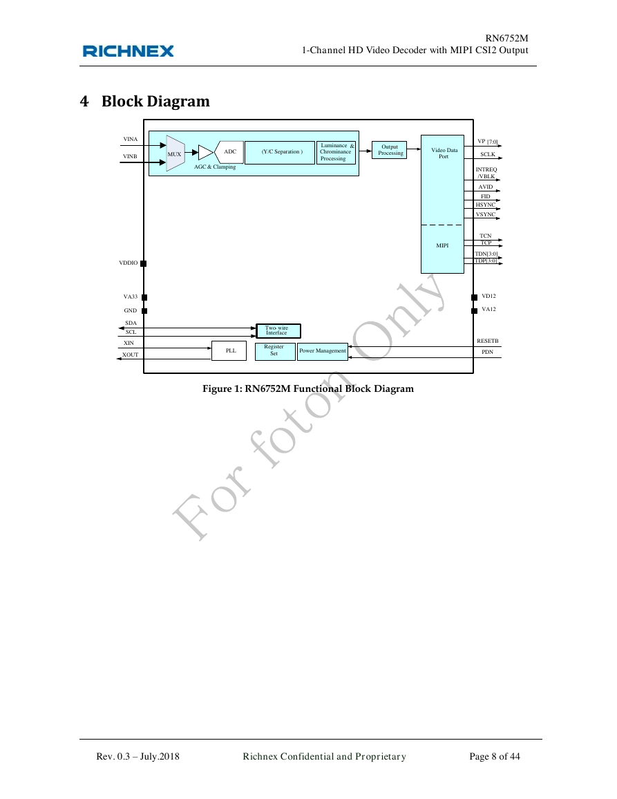
Figure 1: RN6752M Functional Block Diagram
Rev. 0.3 – July.2018 Richnex Confidential and Proprietary Page 8 of 44
Video Data PortSCLKOutputProcessingAGC & ClampingLuminance & Chrominance ProcessingADCVINA(Y/C Separation)VP[7:0]PLLXIN SCLSDATwo-wireInterfaceRESETBRegister SetPower ManagementXOUTINTREQ/VBLKAVIDFIDHSYNCVSYNCPDNVDDIOVA33VD12VA12GNDTCNTCPTDN[3:0]TDP[3:0]MIPI MUXVINB�


 2023年江西萍乡中考道德与法治真题及答案.doc
 2012年重庆南川中考生物真题及答案.doc
 2013年江西师范大学地理学综合及文艺理论基础考研真题.doc
 2020年四川甘孜小升初语文真题及答案I卷.doc
 2020年注册岩土工程师专业基础考试真题及答案.doc
 2023-2024学年福建省厦门市九年级上学期数学月考试题及答案.doc
 2021-2022学年辽宁省沈阳市大东区九年级上学期语文期末试题及答案.doc
 2022-2023学年北京东城区初三第一学期物理期末试卷及答案.doc
 2018上半年江西教师资格初中地理学科知识与教学能力真题及答案.doc
 2012年河北国家公务员申论考试真题及答案-省级.doc
 2020-2021学年江苏省扬州市江都区邵樊片九年级上学期数学第一次质量检测试题及答案.doc
 2022下半年黑龙江教师资格证中学综合素质真题及答案.doc