2354235 11/2008
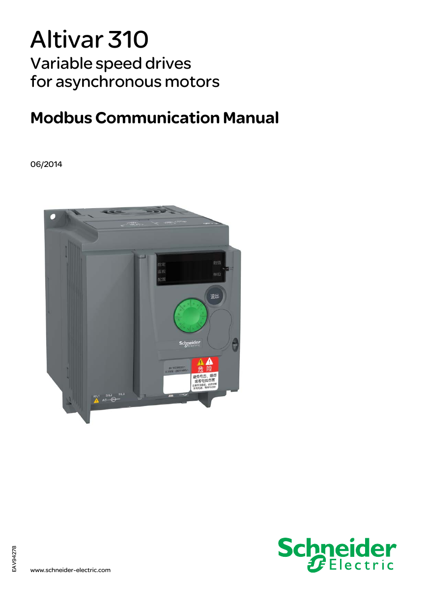
Altivar 310
Variable speed drives
for asynchronous motors
Modbus Communication Manual
06/2014
8
7
2
4
9
V
A
E
www.schneider-electric.com
�
�
Contents
Important Information __________________________________________________________________________________________ 4
Before you begin______________________________________________________________________________________________ 5
Documentation structure________________________________________________________________________________________ 7
Presentation _________________________________________________________________________________________________ 8
Connection to RS485 bus_______________________________________________________________________________________ 9
Configuration of the Modbus serial port ___________________________________________________________________________ 10
IO Scanner configuration parameters_____________________________________________________________________________ 11
Modbus Functions ___________________________________________________________________________________________ 13
ATV310 state machine ________________________________________________________________________________________ 18
Application example __________________________________________________________________________________________ 22
Connection to RS485 bus______________________________________________________________________________________ 25
EAV94278 06/2014
3
�
Important Information
NOTICE
Read these instructions carefully, and look at the equipment to become familiar with the device before trying to install, operate, or maintain
it. The following special messages may appear throughout this documentation or on the equipment to warn of potential hazards or to call
attention to information that clarifies or simplifies a procedure.
The addition of this symbol to a Danger or Warning safety label indicates that an electrical hazard exists, which will result in
personal injury if the instructions are not followed.
This is the safety alert symbol. It is used to alert you to potential personal injury hazards. Obey all safety messages that follow
this symbol to avoid possible injury or death.
DANGER indicates an imminently hazardous situation, which, if not avoided, will result in death or serious injury.
DANGER
WARNING indicates a potentially hazardous situation, which, if not avoided, can result in death or serious injury.
WARNING
CAUTION indicates a potentially hazardous situation, which, if not avoided, can result in minor or moderate injury.
CAUTION
NOTICE
NOTICE, used without the safety alert symbol, indicates a potentially hazardous situation which, if not avoided, can
result in property damage.
PLEASE NOTE
The word "drive" as used in this manual refers to the controller portion of the adjustable speed drive as defined by NEC.
Electrical equipment should be installed, operated, serviced, and maintained only by qualified personnel. No responsibility is assumed by
Schneider Electric for any consequences arising out of the use of this material.
© 2014 Schneider Electric. All Rights Reserved
4
EAV94278 06/2014
�
Before you begin
Read and understand these instructions before performing any procedure with this drive.
DANGER
HAZARD OF ELECTRIC SHOCK, EXPLOSION, OR ARC FLASH
• Only appropriately trained persons who are familiar with and understand the contents of this manual and all other pertinent product
documentation and who have received safety training to recognize and avoid hazards involved are authorized to work on and with this
drive system. Installation, adjustment, repair, and maintenance must be performed by qualified personnel.
• The system integrator is responsible for compliance with all local and national electrical code requirements as well as all other
applicable regulations with respect to grounding of all equipment.
• Many components of the product, including the printed circuit boards, operate with mains voltage. Do not touch. Use only electrically
insulated tools.
to prevent rotation.
• Do not touch unshielded components or terminals with voltage present.
• Motors can generate voltage when the shaft is rotated. Before performing any type of work on the drive system, block the motor shaft
• AC voltage can couple voltage to unused conductors in the motor cable. Insulate both ends of unused conductors of the motor cable.
• Do not short across the DC bus terminals or the DC bus capacitors or the braking resistor terminals.
• Before performing work on the drive system:
- Disconnect all power, including external control power that may be present.
- Place a "Do Not Turn On" label on all power switches.
- Lock all power switches in the open position.
- Wait 15minutes to allow the DC bus capacitors to discharge. The DC bus LED is not an indicator of the absence of DC bus voltage
that can exceed 800Vdc.
< 42Vdc.
- Measure the voltage on the DC bus between the DC bus terminals using a properly rated voltmeter to verify that the voltage is
- If the DC bus capacitors do not discharge properly, contact your local Schneider Electric representative.
• Install and close all covers before applying voltage.
Failure to follow these instructions will result in death or serious injury.
DANGER
UNINTENDED EQUIPMENT OPERATION
• Read and understand this manual before installing or operating the ATV310 drive.
• Any changes made to the parameter settings must be performed by qualified personnel.
Failure to follow these instructions will result in death or serious injury.
WARNING
DAMAGED DRIVE EQUIPMENT
Do not operate or install any drive or drive accessory that appears damaged.
Failure to follow these instructions can result in death, serious injury, or equipment damage.
EAV94278 06/2014
5
�
Before you begin
WARNING
LOSS OF CONTROL
• The designer of any control scheme must consider the potential failure modes of control paths and, for critical control functions,
provide a means to achieve a safe state during and after a path failure. Examples of critical control functions are emergency stop,
overtravel stop, power outage, and restart.
• Separate or redundant control paths must be provided for critical control functions.
• System control paths may include communication links. Consideration must be given to the implications of unanticipated
transmission delays or failures of the link.
• Observe all accident prevention regulations and local safety guidelines. (a)
• Each implementation of the product must be individually and thoroughly tested for proper operation before being placed into service.
Failure to follow these instructions can result in death, serious injury or equipment damage.
a. For USA: Additional information, refer to NEMA ICS 1.1 (latest edition), “Safety Guidelines for the Application, Installation, and
Maintenance of Solid State Control” and to NEMA ICS 7.1 (latest edition), “Safety Standards for Construction and Guide for Selection,
Installation and Operation of Adjustable Speed Drive Systems.”
6
EAV94278 06/2014
�
Documentation structure
The following Altivar 310 technical documents are available on the Schneider Electric website (www.schneider-electric.com).
ATV310 Quick Start Guide (EAV94272)
The Quick Start describes how to wire and configure the drive to start motor quickly and simply for simple applications.
This document is delivered with the drive with an Annex (S1A58684) for Short Circuit Current Ratings (SCCR) and branch circuit protection.
ATV310 User manual ( EAV94277)
This manual describes how to install, program and operate the drive.
ATV310 Modbus Communication manual (EAV94278)
This manual describes the assembly, connection to the bus or network, signaling, diagnostics, and configuration of the communication-
specific parameters via the 7 segment LED display.
It also describes the communication services of the Modbus protocol.
This manual includes all Modbus addresses. It explains the operating mode specific to communication (state chart).
ATV310 Modbus parameters description file ( EAV94279)
All the parameters are grouped together in an Excel file with the following data:
• Code
• Name
• Modbus Addresses
• Category
• Read/write access
• Type: signed numerical, unsigned numerical, etc.
• Unit
• Factory setting
• Minimum value
• Maximum value
• Display on the 7-segment integrated display terminal
• Relevant menu
• This file offers the option of sorting and arranging the data according to any criterion chosen by the user.
DANGER
UNINTENDED EQUIPMENT OPERATION
• Read and understand this manual before installing or operating the ATV310 drive.
• Any changes made to the parameter settings must be performed by qualified personnel.
• The excel file does not describe the behaviour of the parameters. Before any modification, refer to the ATV310 User Manual.
Failure to follow these instructions will result in death or serious injury.
EAV94278 06/2014
7
�
Presentation
The Modbus socket on the ATV310 can be used for the following functions:
• Configuration
• Settings
• Control
• Monitoring
The ATV310 fc drive supports:
• The 2-wire RS485 physical layer
• The RTU transmission mode
8
EAV94278 06/2014
�





 2023年江西萍乡中考道德与法治真题及答案.doc
 2012年重庆南川中考生物真题及答案.doc
 2013年江西师范大学地理学综合及文艺理论基础考研真题.doc
 2020年四川甘孜小升初语文真题及答案I卷.doc
 2020年注册岩土工程师专业基础考试真题及答案.doc
 2023-2024学年福建省厦门市九年级上学期数学月考试题及答案.doc
 2021-2022学年辽宁省沈阳市大东区九年级上学期语文期末试题及答案.doc
 2022-2023学年北京东城区初三第一学期物理期末试卷及答案.doc
 2018上半年江西教师资格初中地理学科知识与教学能力真题及答案.doc
 2012年河北国家公务员申论考试真题及答案-省级.doc
 2020-2021学年江苏省扬州市江都区邵樊片九年级上学期数学第一次质量检测试题及答案.doc
 2022下半年黑龙江教师资格证中学综合素质真题及答案.doc