VanetMobiSim – Vehicular Ad hoc Network mobility
extension to the CanuMobiSim framework
Copyright © 2005-2006 Institut Eurécom/Politecnico di Torino
Contact
Jérôme Härri
Institut Eurécom
Department of Mobile Communications
06904 SophiaAntipolis, France
E-mail: haerri@eurecom.fr
Marco Fiore
Politecnico di Torino
Dipartimento di Elettronica
Corso Duca degli Abruzzi 24, Torino, Italy
E-mail: marco.fiore@polito.it
1
�
Contents
1. Introduction ........................................................................................................................ 3
2. Installation .......................................................................................................................... 3
3. Format of Simulation Scenario ......................................................................................... 4
3.1 Specifying a Simulation Area .................................................................................... 4
3.2 Adding a Global Extension to Simulation ................................................................ 4
3.3 Adding a Node to Simulation ..................................................................................... 5
3.3.1 Specifying the Node’s Initial Position .............................................................. 5
3.4 Adding a Group of Nodes to Simulation .................................................................. 6
4. Globally Specified Extensions ........................................................................................... 7
4.1 Spatial Environment .................................................................................................. 7
4.1.1 Specifying Multi-lane Roads ............................................................................ 8
4.2 Traffic Lights ............................................................................................................. 8
4.3 Graph Representation of Movement Area .............................................................. 9
4.3.1 Specifying a Graph’s Vertex .......................................................................... 10
4.3.2 Specifying a Graph’s Edge ............................................................................ 10
4.4 Space Graph ............................................................................................................. 11
4.4.1 Specifying the Space Graph Clustering ........................................................ 12
4.4.1.1 Specifying a Cluster’s Characterization .............................................. 12
4.5 Producing an Image of the Spatial Model ............................................................. 13
4.6 Producing Simulator-Independent Mobility Traces............................................. 13
4.7 GDF Writer .............................................................................................................. 14
4.8 Parser for TIGER Data Sources ............................................................................ 14
4.8.1 Speed Limits File ............................................................................................ 15
4.8 Parser for GDF Data Sources ................................................................................. 16
5. Node-Specific Extensions (Mobility Models) .................................................................16
5.1 Simulating Node’s Motion using the IDM_IM ......................................................16
5.2 Simulating Node’s Motion using the IDM_LC Model ......................................... 17
2
�
1. Introduction
The Vehicular Ad Hoc Networks Mobility Simulator (VanetMobiSim) is a set of extensions to
CanuMobiSim, a framework for user mobility modeling used by the CANU (Communication in Ad
Hoc Networks for Ubiquitous Computing) Research Group [1], University of Stuttgart. The framework
includes a number of mobility models, as well as parsers for geographic data sources in various
formats, and a visualization module. The framework is easily extensible. It is based on the concept of
pluggable modules.
The set of extensions provided by VanetMobiSim consists mainly on a vehicular spatial model using
GDF-compliant data structures, and a set of vehicular-oriented mobility models. The vehicular spatial
model is composed of spatial elements, their attributes and the relationships linking these spatial
elements in order to describe vehicular areas. The spatial model is created from topological data
obtained in four different ways:
• User-defined – The user defines a set of vertices and edges composing the backbone of the
vehicular spatial model.
• Random – The backbone is randomly generated using the Voronoi tessellations.
• Geographic Data Files (GDF) – Backbone data is obtained from GDF files.
• TIGER/line Files – Similar to the previous one, but based on the TIGER/line files from the US
Census Bureau.
Any one of those methods MUST be loaded AFTER the Spatial Model, as it controls all data
describing the topology. Then, it adds vehicular specific spatial elements such as multi-lane and multi-
flow roads, stop signs and traffic lights.
The main component of the vehicular oriented model is the support of a microscopic level mobility
model named “Intelligent Driving Model with Intersection Management (IDM_IM)” describing
perfectly car-to-car and intersection managements. In the Intelligent Driving Model with Lane
Changing (IDM_LC), we also included an overtaking model (MOBIL), which interacts with IDM_IM
to manage lane changes and vehicle accelerations and decelerations. A Spatial Environment MUST be
loaded for user-oriented and vehicular oriented mobility models to work. A spatial Environment MAY
be loaded for all other mobility models specified in CanuMobiSim.
2. Installation
The framework’s binary files are compressed to a jar-archive. To start the application, you need the
JAVA Runtime Environment (v1.3 or later) [10] and the Xerces2 Java Parser library (v2.4 or later)
[19]. If you work with geographic data in AWML or GDF format, you also need the GeoTransform
package [7].
To launch the framework, change to the directory with framework’s files and type:
java -jar VanetMobiSim.jar [scenario.xml]
The framework simulates user mobility according to a simulation scenario. On exit, it returns one of
the following codes:
•
•
0 – successful execution,
1 – simulation aborted, error message is written to System.err
3
�
3. Format of Simulation Scenario
The simulation scenario for VanetMobiSim is similar to CanuMobiSim’s. It is defined in XML format.
In the notation below, tags or attributes appearing in square brackets (e.g., [] are optional.
3.1 Specifying a Simulation Area
A simulation area is specified using the tag.
[dimension]
[dimension]
[step]
[seed]
[extension_parameters]
[node_parameter]
[nodegroup_parameters]
• dimx – specifies the x-dimension of the simulation are (in meters). Only used in the scenarios
with rectangular-bounded simulation areas.
•
• dimy – specifies the y-dimension of the simulation are (in meters). Only used in the scenarios
with rectangular-bounded simulation areas.
step – specifies the duration of single simulation time-step (in s). If omitted, the value of 1 ms is
used.
seed – specifies the seed of the random number generation used by VanetMobiSim.
extension – adds an instance of a global extension to the simulation.
•
•
• node – adds a node to the simulation.
• nodegroup – adds a group of nodes to the simulation.
3.2 Adding a Global Extension to Simulation
An instance of global extension is added using the tag.
[extension_parameters]
•
class – specifies the name of class to be instantiated. The class must be derived from
de.uni_stuttgart.informatik.canu.mobisim.core.ExtensionModule and be accessible by JVM.
• name – specifies the name of class instance. Used to uniquely identify and reference the
instance in simulation. Most of extensions have their default name predefined.
4
�
Example:
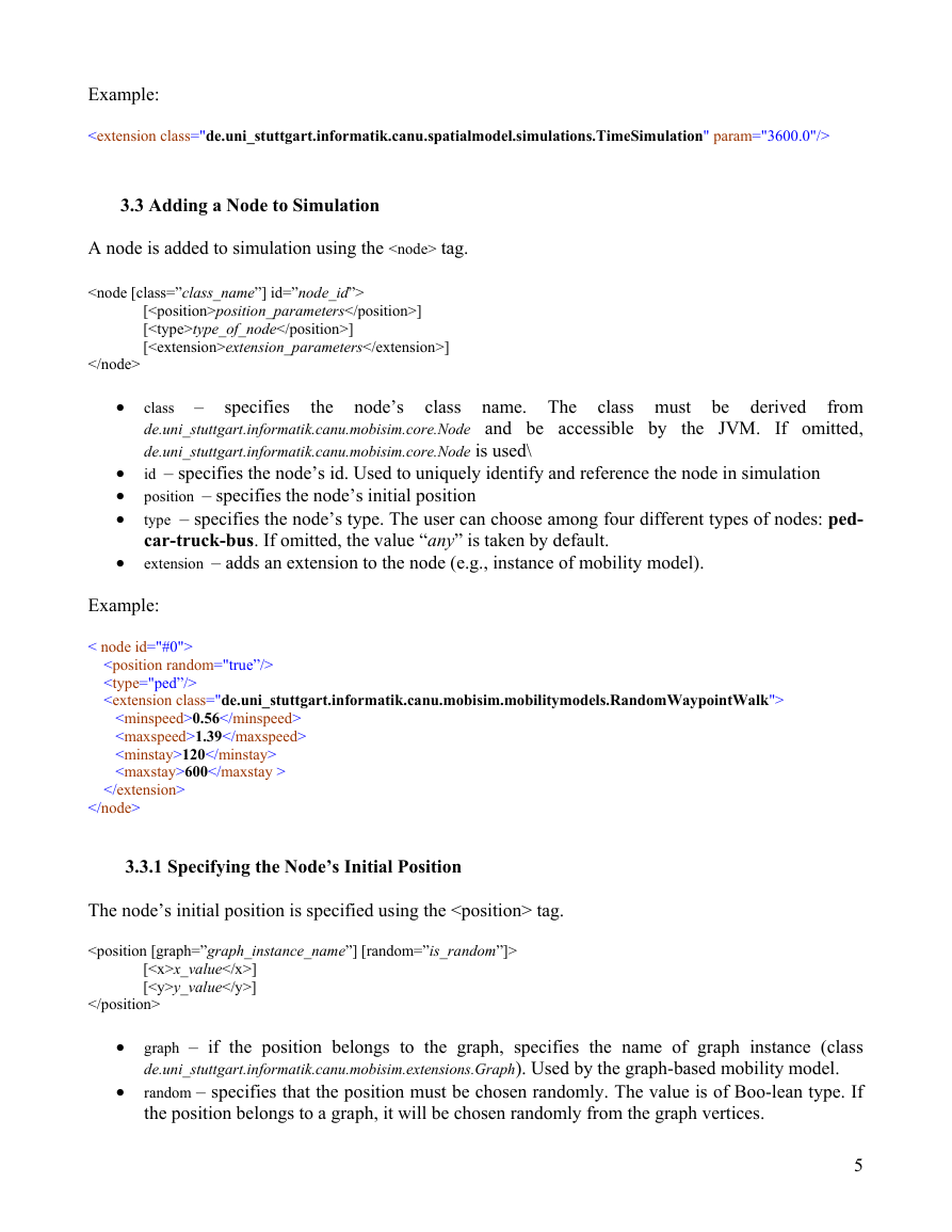
3.3 Adding a Node to Simulation
A node is added to simulation using the
tag.
[position_parameters]
[type_of_node]
[extension_parameters]
•
specifies
the node’s class name. The class must be derived
class –
from
de.uni_stuttgart.informatik.canu.mobisim.core.Node and be accessible by the JVM. If omitted,
de.uni_stuttgart.informatik.canu.mobisim.core.Node is used\
id – specifies the node’s id. Used to uniquely identify and reference the node in simulation
•
• position – specifies the node’s initial position
•
type – specifies the node’s type. The user can choose among four different types of nodes: ped-
car-truck-bus. If omitted, the value “any” is taken by default.
extension – adds an extension to the node (e.g., instance of mobility model).
•
Example:
< node id="#0">
0.56
1.39
120
600
3.3.1 Specifying the Node’s Initial Position
The node’s initial position is specified using the
tag.
[x_value]
[y_value]
•
• graph – if the position belongs to the graph, specifies the name of graph instance (class
de.uni_stuttgart.informatik.canu.mobisim.extensions.Graph). Used by the graph-based mobility model.
random – specifies that the position must be chosen randomly. The value is of Boo-lean type. If
the position belongs to a graph, it will be chosen randomly from the graph vertices.
5
�• x – specifies the position’s x-coordinate (in m).
• y – specifies the position’s y-coordinate (in m).
Example:
12.0
25.0
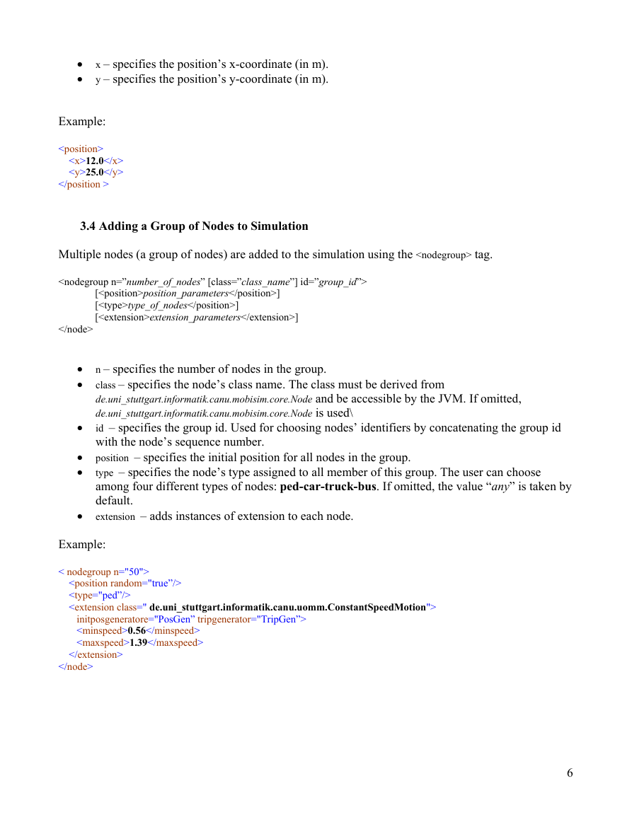
3.4 Adding a Group of Nodes to Simulation
Multiple nodes (a group of nodes) are added to the simulation using the
tag.
[position_parameters]
[type_of_nodes]
[extension_parameters]
•
• n – specifies the number of nodes in the group.
•
class – specifies the node’s class name. The class must be derived from
de.uni_stuttgart.informatik.canu.mobisim.core.Node and be accessible by the JVM. If omitted,
de.uni_stuttgart.informatik.canu.mobisim.core.Node is used\
id – specifies the group id. Used for choosing nodes’ identifiers by concatenating the group id
with the node’s sequence number.
• position – specifies the initial position for all nodes in the group.
•
type – specifies the node’s type assigned to all member of this group. The user can choose
among four different types of nodes: ped-car-truck-bus. If omitted, the value “any” is taken by
default.
extension – adds instances of extension to each node.
•
Example:
< nodegroup n="50">
initposgeneratore="PosGen” tripgenerator="TripGen”>
0.56
1.39
6
� 4. Globally Specified Extensions
The following extensions can be added globally to a simulation. All of them require an instance of
de.uni_stuttgart.informatik.canu.spatialmodel.core.SpatialModel.
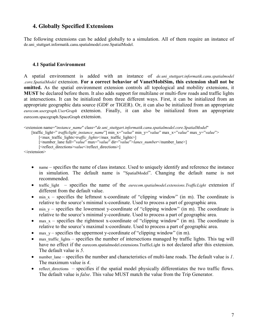
4.1 Spatial Environment
A spatial environment
instance of de.uni_stuttgart.informatik.canu.spatialmodel
.core.SpatialModel extension. For a correct behavior of VanetMobiSim, this extension shall not be
omitted. As the spatial environment extension controls all topological and mobility extensions, it
MUST be declared before them. It also adds support for multilane or multi-flow roads and traffic lights
at intersections. It can be initialized from three different ways. First, it can be initialized from an
appropriate geographic data source (GDF or TIGER). Or, it can also be initialized from an appropriate
eurecom.usergraph.UserGraph extension. Finally, it can also be initialized from an appropriate
eurecom.spacegraph.SpaceGraph extension.
[traffic_lights]
[lanes_number]
[value]
• name – specifies the name of class instance. Used to uniquely identify and reference the instance
in simulation. The default name is “SpatialModel”. Changing the default name is not
recommended.
traffic_light – specifies the name of the eurecom.spatialmodel.extensions.TrafficLight extension if
different from the default value.
• min_x – specifies the leftmost x-coordinate of “clipping window” (in m). The coordinate is
•
relative to the source’s minimal x-coordinate. Used to process a part of geographic area.
• min_y – specifies the lowermost y-coordinate of “clipping window” (in m). The coordinate is
relative to the source’s minimal y-coordinate. Used to process a part of geographic area.
• max_x – specifies the rightmost x-coordinate of “clipping window” (in m). The coordinate is
relative to the source’s maximal x-coordinate. Used to process a part of geographic area.
• max_y – specifies the uppermost y-coordinate of “clipping window” (in m).
• max_traffic_lights – specifies the number of intersections managed by traffic lights. This tag will
have no effect if the eurecom.spatialmodel.extensions.TrafficLight is not declared after this extension.
The default value is 5.
• number_lane – specifies the number and characteristics of multi-lane roads. The default value is 1.
The maximum value is 4.
reflect_directions – specifies if the spatial model physically differentiates the two traffic flows.
The default value is false. This value MUST match the value from the Trip Generator.
•
7
�
Example:
6
true
2
4.1.1 Specifying Multi-lane Roads
The characteristics of multi-lane roads in the Spatial model are specified using the tag.
When specifying a multi-lane road, the spatial model intends to model highways and therefore will
generate a multi-lane highway starting from one border and ending on a different border using the
Dijkstra shortest path algorithm.
lanes_number
• full – specifies whether all roads have multiple lanes or not.
• max – if the attribute is false, specifies the maximum number of roads with multi-lane
capability in the graph, i.e. the size of the subset of roads modeled as highways. If omitted, the
default value is 4.
• dir – specifies if the spatial model physically differentiates the two traffic flows. If the
attribute is true, and are equivalent. If not, allows the user to
differentiate the directional flows of multi-lane roads only. If omitted, the default value is false.
• lanes_number – specifies the number of lanes in multi-lane roads. If omitted, the default value is
1.
Example:
2
for
traffic
lights at
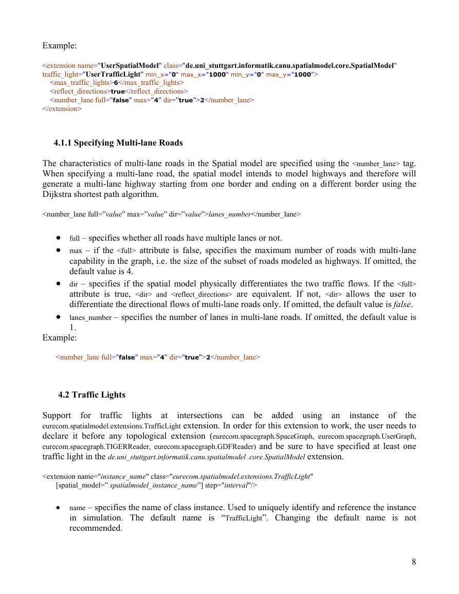
intersections can be added using an
4.2 Traffic Lights
Support
the
eurecom.spatialmodel.extensions.TrafficLight extension. In order for this extension to work, the user needs to
declare it before any topological extension (eurecom.spacegraph.SpaceGraph, eurecom.spacegraph.UserGraph,
eurecom.spacegraph.TIGERReader, eurecom.spacegraph.GDFReader) and be sure to have specified at least one
traffic light in the de.uni_stuttgart.informatik.canu.spatialmodel .core.SpatialModel extension.
instance of
• name – specifies the name of class instance. Used to uniquely identify and reference the instance
in simulation. The default name is “TrafficLight”. Changing the default name is not
recommended.
8
�


 2023年江西萍乡中考道德与法治真题及答案.doc
 2012年重庆南川中考生物真题及答案.doc
 2013年江西师范大学地理学综合及文艺理论基础考研真题.doc
 2020年四川甘孜小升初语文真题及答案I卷.doc
 2020年注册岩土工程师专业基础考试真题及答案.doc
 2023-2024学年福建省厦门市九年级上学期数学月考试题及答案.doc
 2021-2022学年辽宁省沈阳市大东区九年级上学期语文期末试题及答案.doc
 2022-2023学年北京东城区初三第一学期物理期末试卷及答案.doc
 2018上半年江西教师资格初中地理学科知识与教学能力真题及答案.doc
 2012年河北国家公务员申论考试真题及答案-省级.doc
 2020-2021学年江苏省扬州市江都区邵樊片九年级上学期数学第一次质量检测试题及答案.doc
 2022下半年黑龙江教师资格证中学综合素质真题及答案.doc