Micron Confidential and Proprietary
Advance‡
2Gb: x8, x16 NAND Flash Memory
Features
NAND Flash Memory
MT29F2G08ABAEAH4, MT29F2G08ABAEAWP, MT29F2G08ABBEAH4
MT29F2G08ABBEAHC, MT29F2G16ABAEAWP, MT29F2G16ABBEAH4
MT29F2G16ABBEAHC
Features
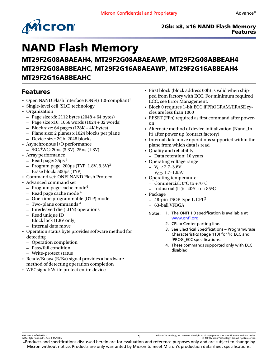
• Open NAND Flash Interface (ONFI) 1.0-compliant1
• Single-level cell (SLC) technology
• Organization
– Page size x8: 2112 bytes (2048 + 64 bytes)
– Page size x16: 1056 words (1024 + 32 words)
– Block size: 64 pages (128K + 4K bytes)
– Plane size: 2 planes x 1024 blocks per plane
– Device size: 2Gb: 2048 blocks
• Asynchronous I/O performance
– tRC/tWC: 20ns (3.3V), 25ns (1.8V)
• Array performance
– Read page: 25µs 3
– Program page: 200µs (TYP: 1.8V, 3.3V)3
– Erase block: 500µs (TYP)
• Command set: ONFI NAND Flash Protocol
• Advanced command set
– Program page cache mode4
– Read page cache mode 4
– One-time programmable (OTP) mode
– Two-plane commands 4
– Interleaved die (LUN) operations
– Read unique ID
– Block lock (1.8V only)
– Internal data move
• Operation status byte provides software method for
detecting
– Operation completion
– Pass/fail condition
– Write-protect status
• Ready/Busy# (R/B#) signal provides a hardware
method of detecting operation completion
• WP# signal: Write protect entire device
• First block (block address 00h) is valid when ship-
ped from factory with ECC. For minimum required
ECC, see Error Management.
• Block 0 requires 1-bit ECC if PROGRAM/ERASE cy-
cles are less than 1000
• RESET (FFh) required as first command after power-
on
• Alternate method of device initialization (Nand_In-
it) after power up (contact factory)
• Internal data move operations supported within the
plane from which data is read
• Quality and reliability
– Data retention: 10 years
• Operating voltage range
– VCC: 2.7–3.6V
– VCC: 1.7–1.95V
• Operating temperature:
– Commercial: 0°C to +70°C
– Industrial (IT): –40ºC to +85ºC
• Package
– 48-pin TSOP type 1, CPL2
– 63-ball VFBGA
Notes:
www.onfi.org.
1. The ONFI 1.0 specification is available at
2. CPL = Center parting line.
3. See Electrical Specifications – Program/Erase
Characteristics (page 110) for tR_ECC and
tPROG_ECC specifications.
4. These commands supported only with ECC
disabled.
PDF: 09005aef83b83f42
Micron Technology, Inc. reserves the right to change products or specifications without notice.
© 2009 Micron Technology, Inc. All rights reserved.
m69a_2gb_nand.pdf – Rev. E 05/10 EN
‡Products and specifications discussed herein are for evaluation and reference purposes only and are subject to change by
Micron without notice. Products are only warranted by Micron to meet Micron's production data sheet specifications.
1
�
Micron Confidential and Proprietary
Advance
2Gb: x8, x16 NAND Flash Memory
Features
Part Numbering Information
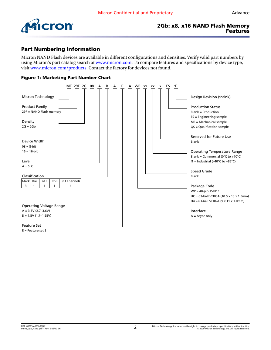
Micron NAND Flash devices are available in different configurations and densities. Verify valid part numbers by
using Micron’s part catalog search at www.micron.com. To compare features and specifications by device type,
visit www.micron.com/products. Contact the factory for devices not found.
Figure 1: Marketing Part Number Chart
MT 29F 2G 08 A B A
E A WP xx xx
x ES
:E
Micron Technology
Product Family
29F = NAND Flash memory
Density
2G = 2Gb
Device Width
08 = 8-bit
16 = 16-bit
Level
A = SLC
I/O Channels
1
1
1
nCE RnB
Classification
Mark Die
1
B
Operating Voltage Range
A = 3.3V (2.7–3.6V)
B = 1.8V (1.7–1.95V)
Design Revision (shrink)
Production Status
Blank = Production
ES = Engineering sample
MS = Mechanical sample
QS = Qualification sample
Reserved for Future Use
Blank
Operating Temperature Range
Blank = Commercial (0°C to +70°C)
IT = Industrial (–40°C to +85°C)
Speed Grade
Blank
Package Code
WP = 48-pin TSOP 1
HC = 63-ball VFBGA (10.5 x 13 x 1.0mm)
H4 = 63-ball VFBGA (9 x 11 x 1.0mm)
Interface
A = Async only
Feature Set
E = Feature set E
PDF: 09005aef83b83f42
m69a_2gb_nand.pdf – Rev. E 05/10 EN
2
Micron Technology, Inc. reserves the right to change products or specifications without notice.
© 2009 Micron Technology, Inc. All rights reserved.
�
Micron Confidential and Proprietary
Advance
2Gb: x8, x16 NAND Flash Memory
Contents
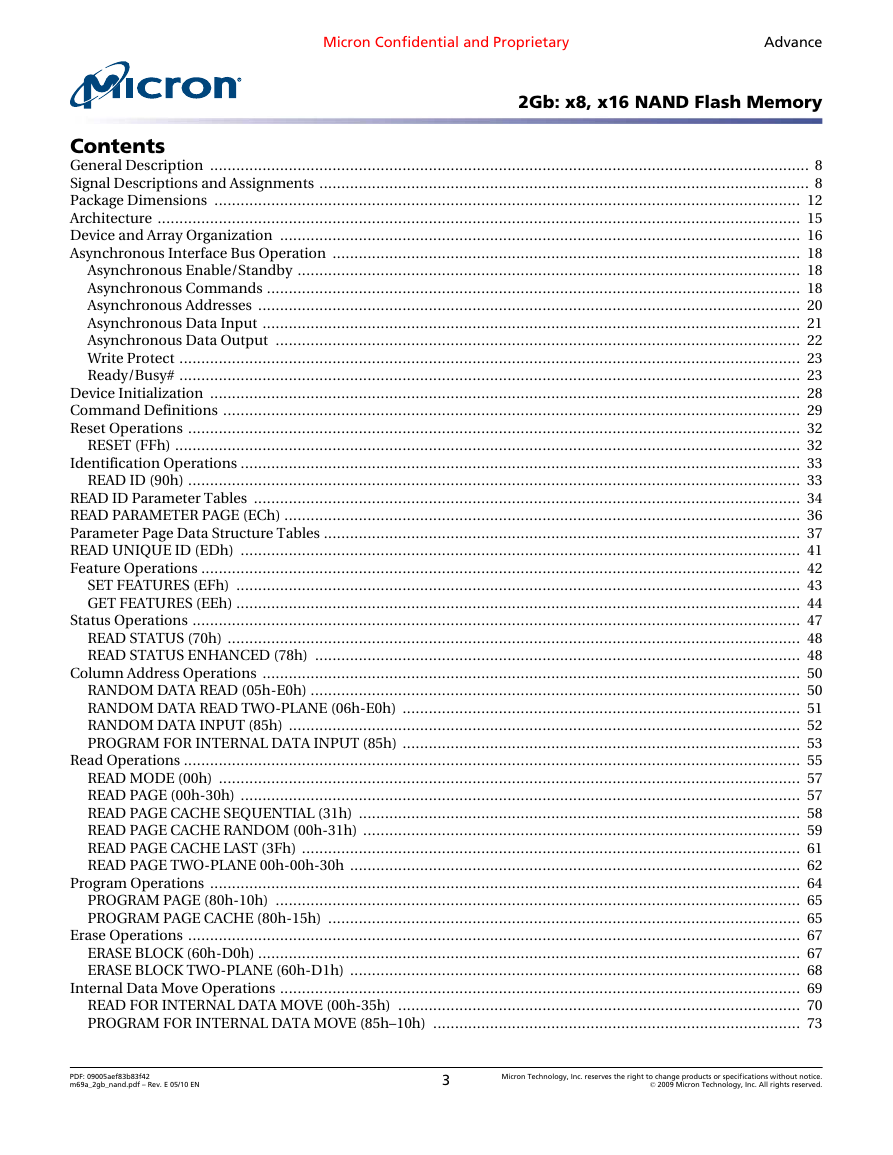
General Description ......................................................................................................................................... 8
Signal Descriptions and Assignments ................................................................................................................ 8
Package Dimensions ...................................................................................................................................... 12
Architecture ................................................................................................................................................... 15
Device and Array Organization ....................................................................................................................... 16
Asynchronous Interface Bus Operation ........................................................................................................... 18
Asynchronous Enable/Standby ................................................................................................................... 18
Asynchronous Commands .......................................................................................................................... 18
Asynchronous Addresses ............................................................................................................................ 20
Asynchronous Data Input ........................................................................................................................... 21
Asynchronous Data Output ........................................................................................................................ 22
Write Protect .............................................................................................................................................. 23
Ready/Busy# .............................................................................................................................................. 23
Device Initialization ....................................................................................................................................... 28
Command Definitions .................................................................................................................................... 29
Reset Operations ............................................................................................................................................ 32
RESET (FFh) ............................................................................................................................................... 32
Identification Operations ................................................................................................................................ 33
READ ID (90h) ............................................................................................................................................ 33
READ ID Parameter Tables ............................................................................................................................. 34
READ PARAMETER PAGE (ECh) ...................................................................................................................... 36
Parameter Page Data Structure Tables ............................................................................................................. 37
READ UNIQUE ID (EDh) ................................................................................................................................ 41
Feature Operations ......................................................................................................................................... 42
SET FEATURES (EFh) ................................................................................................................................. 43
GET FEATURES (EEh) ................................................................................................................................. 44
Status Operations ........................................................................................................................................... 47
READ STATUS (70h) ................................................................................................................................... 48
READ STATUS ENHANCED (78h) ............................................................................................................... 48
Column Address Operations ........................................................................................................................... 50
RANDOM DATA READ (05h-E0h) ................................................................................................................ 50
RANDOM DATA READ TWO-PLANE (06h-E0h) ........................................................................................... 51
RANDOM DATA INPUT (85h) ..................................................................................................................... 52
PROGRAM FOR INTERNAL DATA INPUT (85h) ........................................................................................... 53
Read Operations ............................................................................................................................................. 55
READ MODE (00h) ..................................................................................................................................... 57
READ PAGE (00h-30h) ................................................................................................................................ 57
READ PAGE CACHE SEQUENTIAL (31h) ..................................................................................................... 58
READ PAGE CACHE RANDOM (00h-31h) .................................................................................................... 59
READ PAGE CACHE LAST (3Fh) .................................................................................................................. 61
READ PAGE TWO-PLANE 00h-00h-30h ....................................................................................................... 62
Program Operations ....................................................................................................................................... 64
PROGRAM PAGE (80h-10h) ........................................................................................................................ 65
PROGRAM PAGE CACHE (80h-15h) ............................................................................................................ 65
Erase Operations ............................................................................................................................................ 67
ERASE BLOCK (60h-D0h) ............................................................................................................................ 67
ERASE BLOCK TWO-PLANE (60h-D1h) ....................................................................................................... 68
Internal Data Move Operations ....................................................................................................................... 69
READ FOR INTERNAL DATA MOVE (00h-35h) ............................................................................................ 70
PROGRAM FOR INTERNAL DATA MOVE (85h–10h) .................................................................................... 73
PDF: 09005aef83b83f42
m69a_2gb_nand.pdf – Rev. E 05/10 EN
3
Micron Technology, Inc. reserves the right to change products or specifications without notice.
© 2009 Micron Technology, Inc. All rights reserved.
�
Micron Confidential and Proprietary
Advance
2Gb: x8, x16 NAND Flash Memory
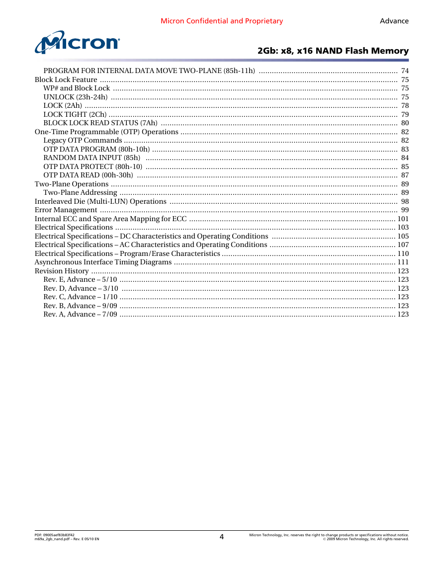
PROGRAM FOR INTERNAL DATA MOVE TWO-PLANE (85h-11h) ................................................................ 74
Block Lock Feature ......................................................................................................................................... 75
WP# and Block Lock ................................................................................................................................... 75
UNLOCK (23h-24h) .................................................................................................................................... 75
LOCK (2Ah) ................................................................................................................................................ 78
LOCK TIGHT (2Ch) ..................................................................................................................................... 79
BLOCK LOCK READ STATUS (7Ah) ............................................................................................................. 80
One-Time Programmable (OTP) Operations .................................................................................................... 82
Legacy OTP Commands .............................................................................................................................. 82
OTP DATA PROGRAM (80h-10h) ................................................................................................................. 83
RANDOM DATA INPUT (85h) .................................................................................................................... 84
OTP DATA PROTECT (80h-10) .................................................................................................................... 85
OTP DATA READ (00h-30h) ........................................................................................................................ 87
Two-Plane Operations .................................................................................................................................... 89
Two-Plane Addressing ................................................................................................................................ 89
Interleaved Die (Multi-LUN) Operations ......................................................................................................... 98
Error Management ......................................................................................................................................... 99
Internal ECC and Spare Area Mapping for ECC ............................................................................................... 101
Electrical Specifications ................................................................................................................................. 103
Electrical Specifications – DC Characteristics and Operating Conditions ......................................................... 105
Electrical Specifications – AC Characteristics and Operating Conditions .......................................................... 107
Electrical Specifications – Program/Erase Characteristics ................................................................................ 110
Asynchronous Interface Timing Diagrams ...................................................................................................... 111
Revision History ............................................................................................................................................ 123
Rev. E, Advance – 5/10 ............................................................................................................................... 123
Rev. D, Advance – 3/10 .............................................................................................................................. 123
Rev. C, Advance – 1/10 ............................................................................................................................... 123
Rev. B, Advance – 9/09 ............................................................................................................................... 123
Rev. A, Advance – 7/09 ............................................................................................................................... 123
PDF: 09005aef83b83f42
m69a_2gb_nand.pdf – Rev. E 05/10 EN
4
Micron Technology, Inc. reserves the right to change products or specifications without notice.
© 2009 Micron Technology, Inc. All rights reserved.
�
Micron Confidential and Proprietary
Advance
2Gb: x8, x16 NAND Flash Memory
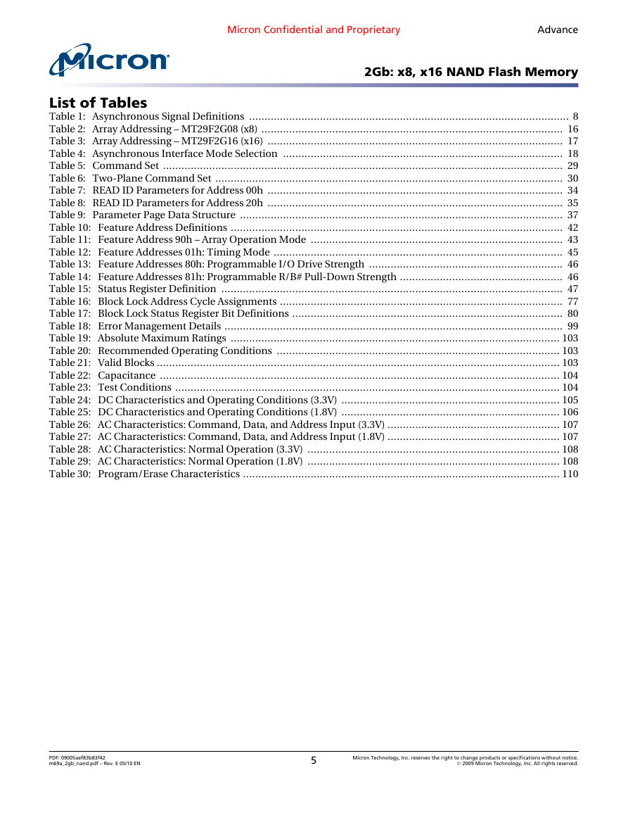
List of Tables
Table 1: Asynchronous Signal Definitions ........................................................................................................ 8
Table 2: Array Addressing – MT29F2G08 (x8) .................................................................................................. 16
Table 3: Array Addressing – MT29F2G16 (x16) ................................................................................................ 17
Table 4: Asynchronous Interface Mode Selection ........................................................................................... 18
Table 5: Command Set .................................................................................................................................. 29
Table 6: Two-Plane Command Set ................................................................................................................. 30
Table 7: READ ID Parameters for Address 00h ................................................................................................ 34
Table 8: READ ID Parameters for Address 20h ................................................................................................ 35
Table 9: Parameter Page Data Structure ......................................................................................................... 37
Table 10: Feature Address Definitions ............................................................................................................ 42
Table 11: Feature Address 90h – Array Operation Mode .................................................................................. 43
Table 12: Feature Addresses 01h: Timing Mode .............................................................................................. 45
Table 13: Feature Addresses 80h: Programmable I/O Drive Strength ............................................................... 46
Table 14: Feature Addresses 81h: Programmable R/B# Pull-Down Strength ..................................................... 46
Table 15: Status Register Definition ............................................................................................................... 47
Table 16: Block Lock Address Cycle Assignments ............................................................................................ 77
Table 17: Block Lock Status Register Bit Definitions ........................................................................................ 80
Table 18: Error Management Details .............................................................................................................. 99
Table 19: Absolute Maximum Ratings ........................................................................................................... 103
Table 20: Recommended Operating Conditions ............................................................................................ 103
Table 21: Valid Blocks ................................................................................................................................... 103
Table 22: Capacitance .................................................................................................................................. 104
Table 23: Test Conditions ............................................................................................................................. 104
Table 24: DC Characteristics and Operating Conditions (3.3V) ....................................................................... 105
Table 25: DC Characteristics and Operating Conditions (1.8V) ....................................................................... 106
Table 26: AC Characteristics: Command, Data, and Address Input (3.3V) ........................................................ 107
Table 27: AC Characteristics: Command, Data, and Address Input (1.8V) ........................................................ 107
Table 28: AC Characteristics: Normal Operation (3.3V) .................................................................................. 108
Table 29: AC Characteristics: Normal Operation (1.8V) .................................................................................. 108
Table 30: Program/Erase Characteristics ....................................................................................................... 110
PDF: 09005aef83b83f42
m69a_2gb_nand.pdf – Rev. E 05/10 EN
5
Micron Technology, Inc. reserves the right to change products or specifications without notice.
© 2009 Micron Technology, Inc. All rights reserved.
�
Micron Confidential and Proprietary
Advance
2Gb: x8, x16 NAND Flash Memory
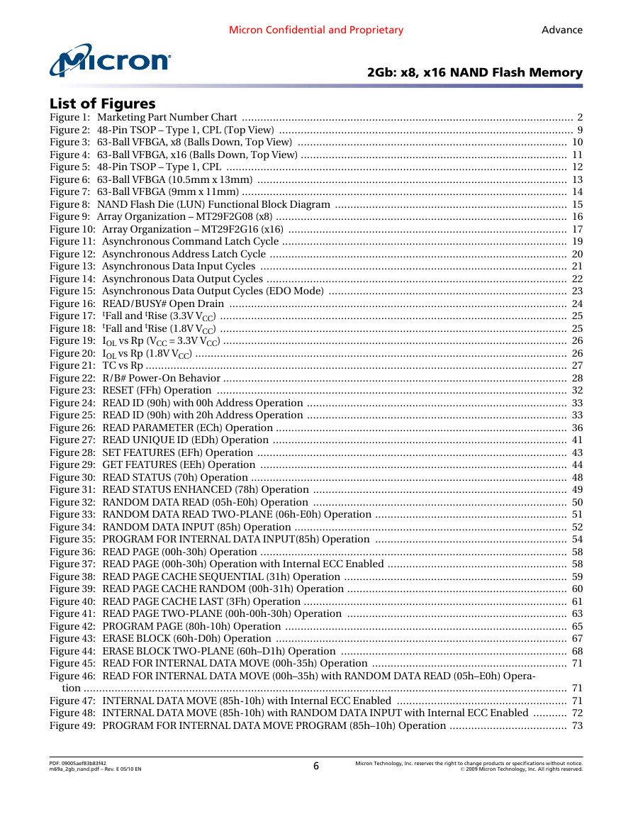
List of Figures
Figure 1: Marketing Part Number Chart ........................................................................................................... 2
Figure 2: 48-Pin TSOP – Type 1, CPL (Top View) ............................................................................................... 9
Figure 3: 63-Ball VFBGA, x8 (Balls Down, Top View) ....................................................................................... 10
Figure 4: 63-Ball VFBGA, x16 (Balls Down, Top View) ...................................................................................... 11
Figure 5: 48-Pin TSOP – Type 1, CPL .............................................................................................................. 12
Figure 6: 63-Ball VFBGA (10.5mm x 13mm) .................................................................................................... 13
Figure 7: 63-Ball VFBGA (9mm x 11mm) ......................................................................................................... 14
Figure 8: NAND Flash Die (LUN) Functional Block Diagram ........................................................................... 15
Figure 9: Array Organization – MT29F2G08 (x8) .............................................................................................. 16
Figure 10: Array Organization – MT29F2G16 (x16) .......................................................................................... 17
Figure 11: Asynchronous Command Latch Cycle ............................................................................................ 19
Figure 12: Asynchronous Address Latch Cycle ................................................................................................ 20
Figure 13: Asynchronous Data Input Cycles ................................................................................................... 21
Figure 14: Asynchronous Data Output Cycles ................................................................................................. 22
Figure 15: Asynchronous Data Output Cycles (EDO Mode) ............................................................................. 23
Figure 16: READ/BUSY# Open Drain ............................................................................................................. 24
Figure 17: tFall and tRise (3.3V VCC) ................................................................................................................ 25
Figure 18: tFall and tRise (1.8V VCC) ................................................................................................................ 25
Figure 19: IOL vs Rp (VCC = 3.3V VCC) ............................................................................................................... 26
Figure 20: IOL vs Rp (1.8V VCC) ........................................................................................................................ 26
Figure 21: TC vs Rp ........................................................................................................................................ 27
Figure 22: R/B# Power-On Behavior ............................................................................................................... 28
Figure 23: RESET (FFh) Operation ................................................................................................................. 32
Figure 24: READ ID (90h) with 00h Address Operation .................................................................................... 33
Figure 25: READ ID (90h) with 20h Address Operation .................................................................................... 33
Figure 26: READ PARAMETER (ECh) Operation .............................................................................................. 36
Figure 27: READ UNIQUE ID (EDh) Operation ............................................................................................... 41
Figure 28: SET FEATURES (EFh) Operation .................................................................................................... 43
Figure 29: GET FEATURES (EEh) Operation ................................................................................................... 44
Figure 30: READ STATUS (70h) Operation ...................................................................................................... 48
Figure 31: READ STATUS ENHANCED (78h) Operation .................................................................................. 49
Figure 32: RANDOM DATA READ (05h-E0h) Operation .................................................................................. 50
Figure 33: RANDOM DATA READ TWO-PLANE (06h-E0h) Operation .............................................................. 51
Figure 34: RANDOM DATA INPUT (85h) Operation ........................................................................................ 52
Figure 35: PROGRAM FOR INTERNAL DATA INPUT(85h) Operation .............................................................. 54
Figure 36: READ PAGE (00h-30h) Operation ................................................................................................... 58
Figure 37: READ PAGE (00h-30h) Operation with Internal ECC Enabled .......................................................... 58
Figure 38: READ PAGE CACHE SEQUENTIAL (31h) Operation ........................................................................ 59
Figure 39: READ PAGE CACHE RANDOM (00h-31h) Operation ....................................................................... 60
Figure 40: READ PAGE CACHE LAST (3Fh) Operation ..................................................................................... 61
Figure 41: READ PAGE TWO-PLANE (00h-00h-30h) Operation ....................................................................... 63
Figure 42: PROGRAM PAGE (80h-10h) Operation ........................................................................................... 65
Figure 43: ERASE BLOCK (60h-D0h) Operation .............................................................................................. 67
Figure 44: ERASE BLOCK TWO-PLANE (60h–D1h) Operation ......................................................................... 68
Figure 45: READ FOR INTERNAL DATA MOVE (00h-35h) Operation ............................................................... 71
Figure 46: READ FOR INTERNAL DATA MOVE (00h–35h) with RANDOM DATA READ (05h–E0h) Opera-
tion ............................................................................................................................................................ 71
Figure 47: INTERNAL DATA MOVE (85h-10h) with Internal ECC Enabled ....................................................... 71
Figure 48: INTERNAL DATA MOVE (85h-10h) with RANDOM DATA INPUT with Internal ECC Enabled ........... 72
Figure 49: PROGRAM FOR INTERNAL DATA MOVE PROGRAM (85h–10h) Operation ...................................... 73
PDF: 09005aef83b83f42
m69a_2gb_nand.pdf – Rev. E 05/10 EN
6
Micron Technology, Inc. reserves the right to change products or specifications without notice.
© 2009 Micron Technology, Inc. All rights reserved.
�
Micron Confidential and Proprietary
Advance
2Gb: x8, x16 NAND Flash Memory
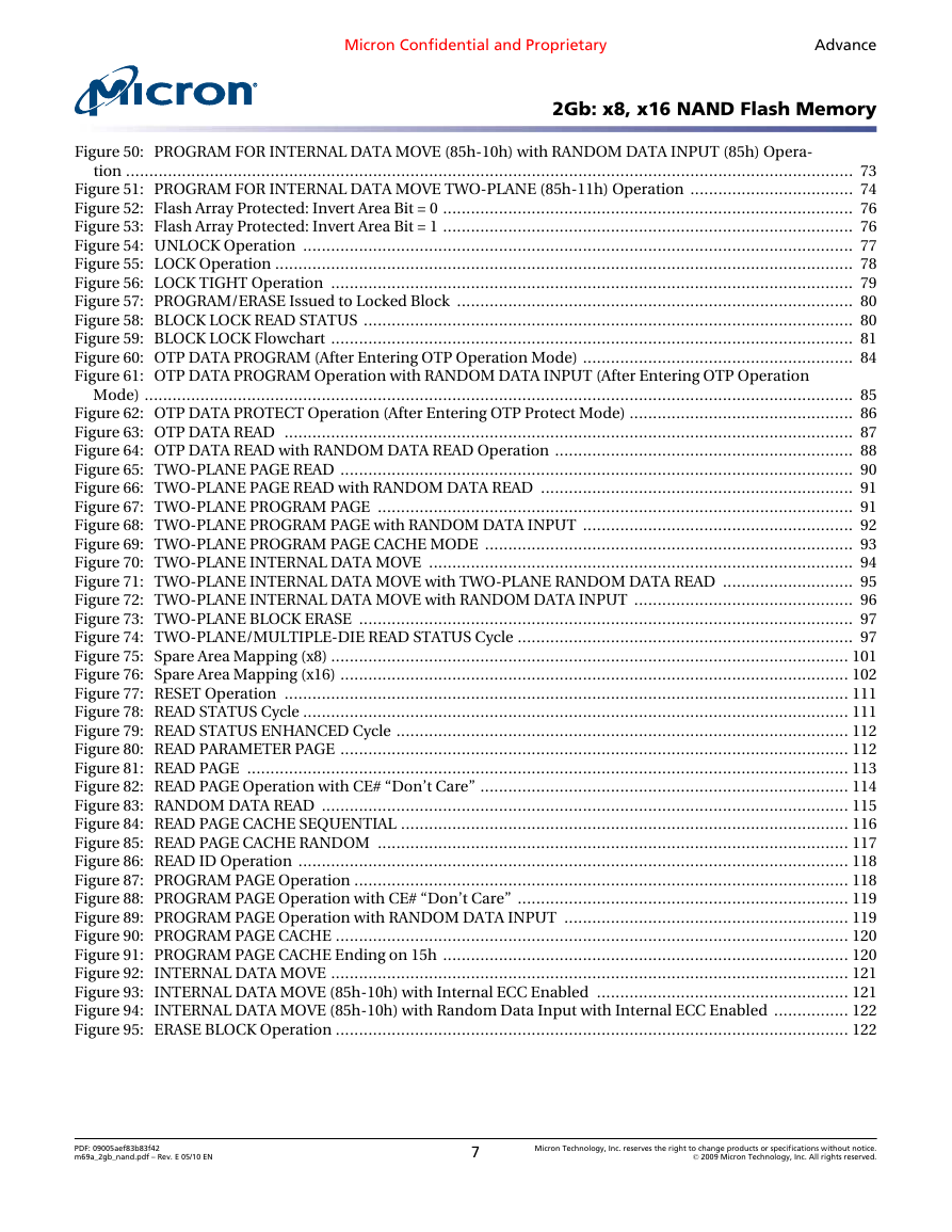
Figure 50: PROGRAM FOR INTERNAL DATA MOVE (85h-10h) with RANDOM DATA INPUT (85h) Opera-
tion ............................................................................................................................................................ 73
Figure 51: PROGRAM FOR INTERNAL DATA MOVE TWO-PLANE (85h-11h) Operation ................................... 74
Figure 52: Flash Array Protected: Invert Area Bit = 0 ........................................................................................ 76
Figure 53: Flash Array Protected: Invert Area Bit = 1 ........................................................................................ 76
Figure 54: UNLOCK Operation ...................................................................................................................... 77
Figure 55: LOCK Operation ............................................................................................................................ 78
Figure 56: LOCK TIGHT Operation ................................................................................................................ 79
Figure 57: PROGRAM/ERASE Issued to Locked Block ..................................................................................... 80
Figure 58: BLOCK LOCK READ STATUS ......................................................................................................... 80
Figure 59: BLOCK LOCK Flowchart ................................................................................................................ 81
Figure 60: OTP DATA PROGRAM (After Entering OTP Operation Mode) .......................................................... 84
Figure 61: OTP DATA PROGRAM Operation with RANDOM DATA INPUT (After Entering OTP Operation
Mode) ........................................................................................................................................................ 85
Figure 62: OTP DATA PROTECT Operation (After Entering OTP Protect Mode) ................................................ 86
Figure 63: OTP DATA READ .......................................................................................................................... 87
Figure 64: OTP DATA READ with RANDOM DATA READ Operation ................................................................ 88
Figure 65: TWO-PLANE PAGE READ .............................................................................................................. 90
Figure 66: TWO-PLANE PAGE READ with RANDOM DATA READ ................................................................... 91
Figure 67: TWO-PLANE PROGRAM PAGE ...................................................................................................... 91
Figure 68: TWO-PLANE PROGRAM PAGE with RANDOM DATA INPUT .......................................................... 92
Figure 69: TWO-PLANE PROGRAM PAGE CACHE MODE ............................................................................... 93
Figure 70: TWO-PLANE INTERNAL DATA MOVE ........................................................................................... 94
Figure 71: TWO-PLANE INTERNAL DATA MOVE with TWO-PLANE RANDOM DATA READ ............................ 95
Figure 72: TWO-PLANE INTERNAL DATA MOVE with RANDOM DATA INPUT ............................................... 96
Figure 73: TWO-PLANE BLOCK ERASE .......................................................................................................... 97
Figure 74: TWO-PLANE/MULTIPLE-DIE READ STATUS Cycle ........................................................................ 97
Figure 75: Spare Area Mapping (x8) ............................................................................................................... 101
Figure 76: Spare Area Mapping (x16) ............................................................................................................. 102
Figure 77: RESET Operation ......................................................................................................................... 111
Figure 78: READ STATUS Cycle ..................................................................................................................... 111
Figure 79: READ STATUS ENHANCED Cycle ................................................................................................. 112
Figure 80: READ PARAMETER PAGE ............................................................................................................. 112
Figure 81: READ PAGE ................................................................................................................................. 113
Figure 82: READ PAGE Operation with CE# “Don’t Care” ............................................................................... 114
Figure 83: RANDOM DATA READ ................................................................................................................. 115
Figure 84: READ PAGE CACHE SEQUENTIAL ................................................................................................ 116
Figure 85: READ PAGE CACHE RANDOM ..................................................................................................... 117
Figure 86: READ ID Operation ...................................................................................................................... 118
Figure 87: PROGRAM PAGE Operation .......................................................................................................... 118
Figure 88: PROGRAM PAGE Operation with CE# “Don’t Care” ....................................................................... 119
Figure 89: PROGRAM PAGE Operation with RANDOM DATA INPUT ............................................................. 119
Figure 90: PROGRAM PAGE CACHE .............................................................................................................. 120
Figure 91: PROGRAM PAGE CACHE Ending on 15h ....................................................................................... 120
Figure 92: INTERNAL DATA MOVE ............................................................................................................... 121
Figure 93: INTERNAL DATA MOVE (85h-10h) with Internal ECC Enabled ...................................................... 121
Figure 94: INTERNAL DATA MOVE (85h-10h) with Random Data Input with Internal ECC Enabled ................ 122
Figure 95: ERASE BLOCK Operation .............................................................................................................. 122
PDF: 09005aef83b83f42
m69a_2gb_nand.pdf – Rev. E 05/10 EN
7
Micron Technology, Inc. reserves the right to change products or specifications without notice.
© 2009 Micron Technology, Inc. All rights reserved.
�
Micron Confidential and Proprietary
Advance
2Gb: x8, x16 NAND Flash Memory
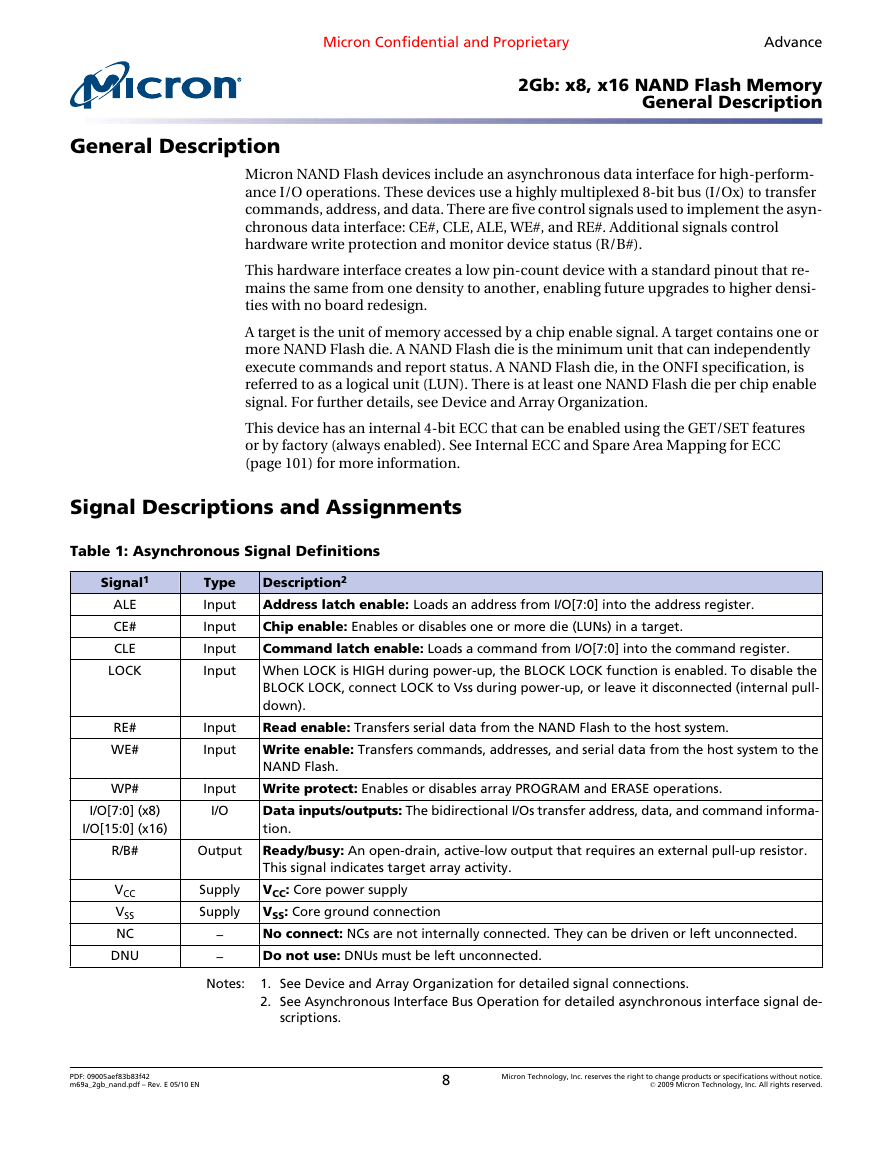
General Description
General Description
Micron NAND Flash devices include an asynchronous data interface for high-perform-
ance I/O operations. These devices use a highly multiplexed 8-bit bus (I/Ox) to transfer
commands, address, and data. There are five control signals used to implement the asyn-
chronous data interface: CE#, CLE, ALE, WE#, and RE#. Additional signals control
hardware write protection and monitor device status (R/B#).
This hardware interface creates a low pin-count device with a standard pinout that re-
mains the same from one density to another, enabling future upgrades to higher densi-
ties with no board redesign.
A target is the unit of memory accessed by a chip enable signal. A target contains one or
more NAND Flash die. A NAND Flash die is the minimum unit that can independently
execute commands and report status. A NAND Flash die, in the ONFI specification, is
referred to as a logical unit (LUN). There is at least one NAND Flash die per chip enable
signal. For further details, see Device and Array Organization.
This device has an internal 4-bit ECC that can be enabled using the GET/SET features
or by factory (always enabled). See Internal ECC and Spare Area Mapping for ECC
(page 101) for more information.
Signal Descriptions and Assignments
Table 1: Asynchronous Signal Definitions
Signal1
ALE
CE#
CLE
LOCK
RE#
WE#
WP#
I/O[7:0] (x8)
I/O[15:0] (x16)
R/B#
VCC
VSS
NC
DNU
Type
Input
Input
Input
Input
Input
Input
Input
I/O
Output
Supply
Supply
–
–
Description2
Address latch enable: Loads an address from I/O[7:0] into the address register.
Chip enable: Enables or disables one or more die (LUNs) in a target.
Command latch enable: Loads a command from I/O[7:0] into the command register.
When LOCK is HIGH during power-up, the BLOCK LOCK function is enabled. To disable the
BLOCK LOCK, connect LOCK to Vss during power-up, or leave it disconnected (internal pull-
down).
Read enable: Transfers serial data from the NAND Flash to the host system.
Write enable: Transfers commands, addresses, and serial data from the host system to the
NAND Flash.
Write protect: Enables or disables array PROGRAM and ERASE operations.
Data inputs/outputs: The bidirectional I/Os transfer address, data, and command informa-
tion.
Ready/busy: An open-drain, active-low output that requires an external pull-up resistor.
This signal indicates target array activity.
VCC: Core power supply
VSS: Core ground connection
No connect: NCs are not internally connected. They can be driven or left unconnected.
Do not use: DNUs must be left unconnected.
Notes:
1. See Device and Array Organization for detailed signal connections.
2. See Asynchronous Interface Bus Operation for detailed asynchronous interface signal de-
scriptions.
PDF: 09005aef83b83f42
m69a_2gb_nand.pdf – Rev. E 05/10 EN
8
Micron Technology, Inc. reserves the right to change products or specifications without notice.
© 2009 Micron Technology, Inc. All rights reserved.
�


 2023年江西萍乡中考道德与法治真题及答案.doc
 2012年重庆南川中考生物真题及答案.doc
 2013年江西师范大学地理学综合及文艺理论基础考研真题.doc
 2020年四川甘孜小升初语文真题及答案I卷.doc
 2020年注册岩土工程师专业基础考试真题及答案.doc
 2023-2024学年福建省厦门市九年级上学期数学月考试题及答案.doc
 2021-2022学年辽宁省沈阳市大东区九年级上学期语文期末试题及答案.doc
 2022-2023学年北京东城区初三第一学期物理期末试卷及答案.doc
 2018上半年江西教师资格初中地理学科知识与教学能力真题及答案.doc
 2012年河北国家公务员申论考试真题及答案-省级.doc
 2020-2021学年江苏省扬州市江都区邵樊片九年级上学期数学第一次质量检测试题及答案.doc
 2022下半年黑龙江教师资格证中学综合素质真题及答案.doc