Date of this version: October 2002
1-D FDTD code with PML
Program author: Mats Gustafsson
Department of
Lund Institute of
Sweden
%
%**************************************
*********************************
%
%
%
Electroscience
%
Technology
%
%
%
%
%
%
Erans
%
PML PEC
%
+-----+---+------+---------------------
+-----+------+-->
%
z=Lz
%
Ntrans r=Nz+1
%
%**************************************
*********************************
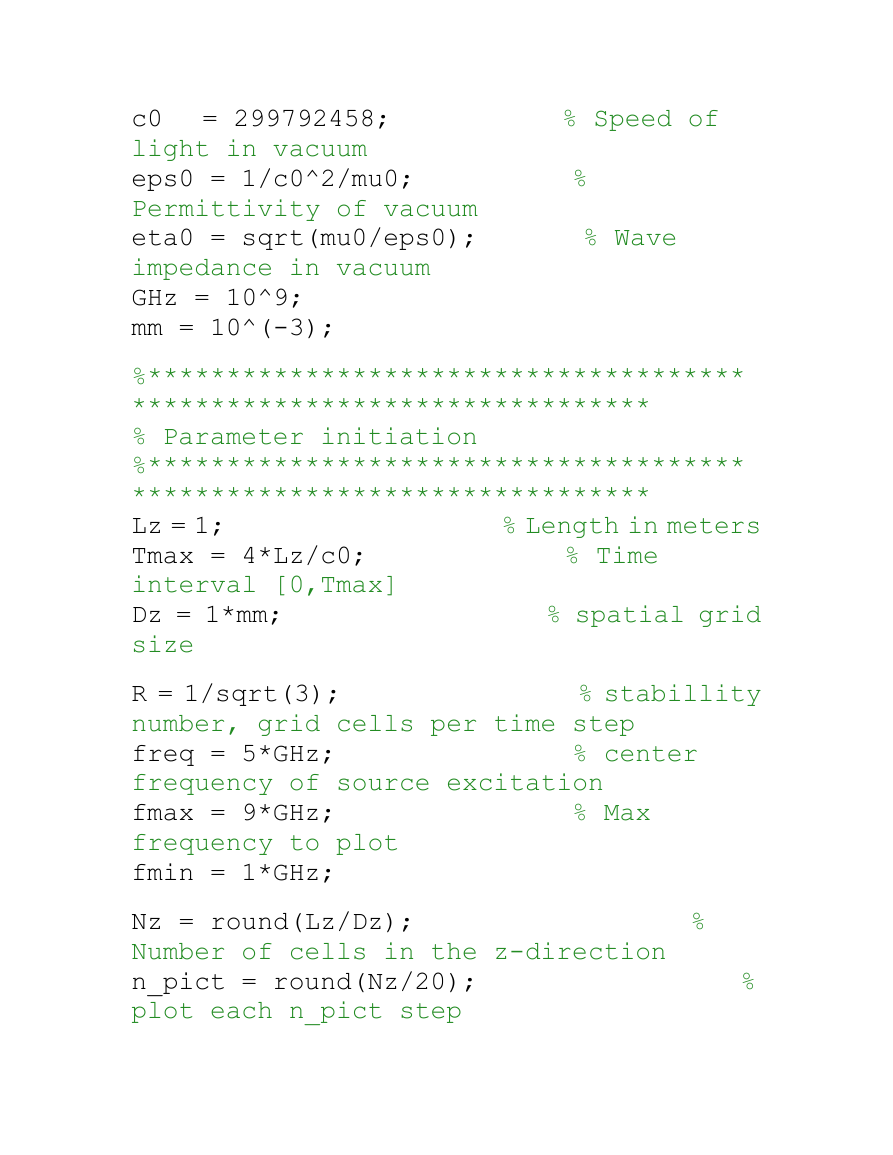
% Physical constants
mu0 = 4e-7 * pi;
of vacuum
z=0
r=1 Nref
Nin
Eref
Ein
PEC PML
objects
% Permeability
�
= 299792458;
%
%
% Speed of
%
% Wave
c0
light in vacuum
eps0 = 1/c0^2/mu0;
Permittivity of vacuum
eta0 = sqrt(mu0/eps0);
impedance in vacuum
GHz = 10^9;
mm = 10^(-3);
%**************************************
*********************************
% Parameter initiation
%**************************************
*********************************
% Length in meters
Lz = 1;
% Time
Tmax = 4*Lz/c0;
interval [0,Tmax]
Dz = 1*mm;
% spatial grid
size
R = 1/sqrt(3);
number, grid cells per time step
freq = 5*GHz;
frequency of source excitation
fmax = 9*GHz;
frequency to plot
fmin = 1*GHz;
Nz = round(Lz/Dz);
Number of cells in the z-direction
n_pict = round(Nz/20);
plot each n_pict step
% stabillity
% center
% Max
�
% linewidth
% Time step
% Number of
linew = 2;
in plot
Dt = Dz*R/c0;
Nt = round(Tmax/Dt);
time steps
Nfft =
max(2^(round(log2(Nt)+1)),2*1024);
Number of points for the fft
z = linspace(0,Lz,Nz+1);
z-coordinates
t = Dt*[0:Nt-1]';
% time
lambda = c0/freq;
% center
wavelength of source excitation
ppw = lambda/Dz
% sample
points per wave length at the center
frequency
omega = 2.0*pi*freq;
frequency
%
%
% angular
% scattered
% near to far
% Number of
Nabc = 1*10;
PML layers to the left and to the right
Nin = 4;
field surface
Nref = 2;
field surface
Ntrans = Nz-2;
Labc = Nabc*Dz;
% PML length
%**************************************
*********************************
% Material parameters
�
%**************************************
*********************************
Nmedia=3;
material
media_par = [1.0 0.0;
permitivity and conductivity
3.4 1*10^(-12); %
3.0 0];
% Number of
% vacuum:
% Number of
% object
objects = 0;
objects
obj_z = Dz/2+[0.500 0.504;
1 between z1 and z2
0.624 0.628;
0.24 0.26];
% Material of
% Color of object
obj_m = [2 2 1];
objects
obj_c = 'rrb';
epsr = ones(Nz-1,1);
sig = zeros(Nz-1,1);
obj_ind = [];
obj_ind(:,1) = ceil(obj_z(:,1)/Dz);
obj_ind(:,2) = floor(obj_z(:,2)/Dz);
obj_frac(:,1) =
obj_ind(:,1)-obj_z(:,1)/Dz;
obj_frac(:,2) =
-obj_ind(:,2)+obj_z(:,2)/Dz;
%break
%epsr(64:73) = 3;
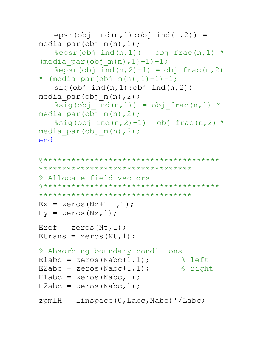
for n=1:objects
�
epsr(obj_ind(n,1):obj_ind(n,2)) =
%epsr(obj_ind(n,1)) = obj_frac(n,1) *
%epsr(obj_ind(n,2)+1) = obj_frac(n,2)
sig(obj_ind(n,1):obj_ind(n,2)) =
%sig(obj_ind(n,1)) = obj_frac(n,1) *
%sig(obj_ind(n,2)+1) = obj_frac(n,2) *
media_par(obj_m(n),1);
(media_par(obj_m(n),1)-1)+1;
* (media_par(obj_m(n),1)-1)+1;
media_par(obj_m(n),2);
media_par(obj_m(n),2);
media_par(obj_m(n),2);
end
%**************************************
*********************************
% Allocate field vectors
%**************************************
*********************************
Ex = zeros(Nz+1 ,1);
Hy = zeros(Nz,1);
Eref = zeros(Nt,1);
Etrans = zeros(Nt,1);
% Absorbing boundary conditions
E1abc = zeros(Nabc+1,1);
E2abc = zeros(Nabc+1,1);
H1abc = zeros(Nabc,1);
H2abc = zeros(Nabc,1);
zpmlH = linspace(0,Labc,Nabc)'/Labc;
% left
% right
�
zpmlE =
linspace(Dz/2,Labc-Dz/2,Nabc-1)'/Labc;
%sigmaH2 = linspace(1,Nabc,Nabc)'/Nabc;
abc_pow = 3;
sigma_max =
-(abc_pow+1)*log(10^(-4))/(2*eta0*Labc)
;
sigmaH2 =
sigma_max*zpmlH.^abc_pow*mu0/eps0;
sigmaE2 = sigma_max*zpmlE.^abc_pow;
sigmaE1 = sigmaE2((Nabc-1):-1:1);
sigmaH1 = sigmaH2(Nabc:-1:1);
figure(4)
plot(sigmaH2)
%break
%**************************************
*********************************
%
%**************************************
*********************************
Hdelay = Dt/2-Dz/2/c0;
% Incident puls from the left
tau = 80.0e-12;
delay = 2.1*tau;
Ein =
sin(omega*(t-delay)).*exp(-((t-delay).^
2/tau^2));
Hin =
1/eta0*sin(omega*(t-delay+Hdelay)).*exp
Wave excitation
�
(-((t-delay+Hdelay).^2/tau^2));
% Incident time harmonic wave from the left
%Ein = sin(omega*(t));
%Hin = 1/eta0*sin(omega*(t+Hdelay));
Einmax = max(abs(Ein));
%**************************************
*********************************
% Time stepping
%**************************************
*********************************
for n = 1:Nt;
% Update H from -Dt/2 to Dt/2
Hy = Hy - (Dt/mu0/Dz) *
diff(Ex,1);
% main grid
Hy(Nin) = Hy(Nin) - (Dt/mu0/Dz) * Ein(n);
H1abc = (H1abc.*(mu0/Dt-sigmaH1/2) -
diff(E1abc)/Dz) ./ (mu0/Dt+sigmaH1/2); %
ABC to the left
diff(E2abc)/Dz) ./ (mu0/Dt+sigmaH2/2); %
ABC to the right
H2abc = (H2abc.*(mu0/Dt-sigmaH2/2) -
% Update E from 0 to Dt
Ex(2:Nz) =
(Ex(2:Nz).*(eps0*epsr/Dt-sig/2) -
diff(Hy,1)/Dz)./(eps0*epsr/Dt+sig/2);
% main grid except boundary
�
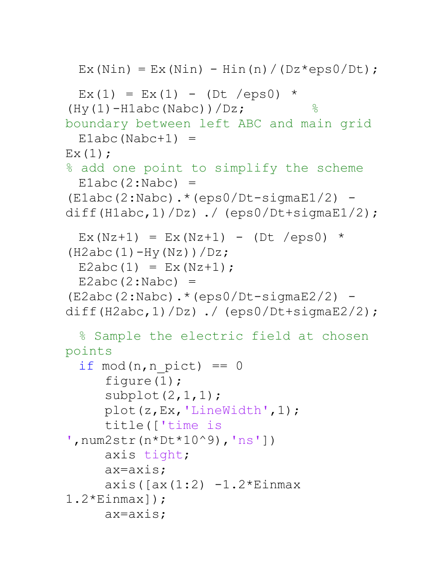
Ex(Nin) = Ex(Nin) - Hin(n)/(Dz*eps0/Dt);
Ex(1) = Ex(1) - (Dt /eps0) *
E1abc(Nabc+1) =
(Hy(1)-H1abc(Nabc))/Dz;
boundary between left ABC and main grid
Ex(1);
% add one point to simplify the scheme
(E1abc(2:Nabc).*(eps0/Dt-sigmaE1/2) -
diff(H1abc,1)/Dz) ./ (eps0/Dt+sigmaE1/2);
E1abc(2:Nabc) =
%
Ex(Nz+1) = Ex(Nz+1) - (Dt /eps0) *
(H2abc(1)-Hy(Nz))/Dz;
E2abc(1) = Ex(Nz+1);
E2abc(2:Nabc) =
(E2abc(2:Nabc).*(eps0/Dt-sigmaE2/2) -
diff(H2abc,1)/Dz) ./ (eps0/Dt+sigmaE2/2);
% Sample the electric field at chosen
if mod(n,n_pict) == 0
points
',num2str(n*Dt*10^9),'ns'])
figure(1);
subplot(2,1,1);
plot(z,Ex,'LineWidth',1);
title(['time is
axis tight;
ax=axis;
axis([ax(1:2) -1.2*Einmax
1.2*Einmax]);
ax=axis;
�


 2023年江西萍乡中考道德与法治真题及答案.doc
 2012年重庆南川中考生物真题及答案.doc
 2013年江西师范大学地理学综合及文艺理论基础考研真题.doc
 2020年四川甘孜小升初语文真题及答案I卷.doc
 2020年注册岩土工程师专业基础考试真题及答案.doc
 2023-2024学年福建省厦门市九年级上学期数学月考试题及答案.doc
 2021-2022学年辽宁省沈阳市大东区九年级上学期语文期末试题及答案.doc
 2022-2023学年北京东城区初三第一学期物理期末试卷及答案.doc
 2018上半年江西教师资格初中地理学科知识与教学能力真题及答案.doc
 2012年河北国家公务员申论考试真题及答案-省级.doc
 2020-2021学年江苏省扬州市江都区邵樊片九年级上学期数学第一次质量检测试题及答案.doc
 2022下半年黑龙江教师资格证中学综合素质真题及答案.doc