How to Develop a RoboCupRescue Agent
for RoboCupRescue Simulation System version 0
1st edition
written by Takeshi Morimoto
edited by RoboCupRescue Technical Committee
mailing list: r-resc@isi.edu
web page: http://robomec.cs.kobe-u.ac.jp/robocup-rescue
�
CONTENTS
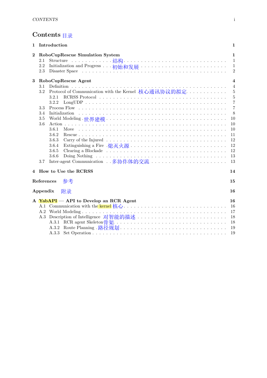
Contents
1 Introduction
2 RoboCupRescue Simulation System
2.1 Structure
2.2
2.3 Disaster Space
. . . . . . . . . . . . . . . . . . . . . . . . . . . . . . . . . . . . . . . . . . . . .
Initialization and Progress . . . . . . . . . . . . . . . . . . . . . . . . . . . . . . . . . . . .
. . . . . . . . . . . . . . . . . . . . . . . . . . . . . . . . . . . . . . . . . .
3 RoboCupRescue Agent
3.1 Definition . . . . . . . . . . . . . . . . . . . . . . . . . . . . . . . . . . . . . . . . . . . . .
3.2 Protocol of Communication with the Kernel . . . . . . . . . . . . . . . . . . . . . . . . . .
3.2.1 RCRSS Protocol
. . . . . . . . . . . . . . . . . . . . . . . . . . . . . . . . . . . . .
3.2.2 LongUDP . . . . . . . . . . . . . . . . . . . . . . . . . . . . . . . . . . . . . . . . .
3.3 Process Flow . . . . . . . . . . . . . . . . . . . . . . . . . . . . . . . . . . . . . . . . . . .
3.4
Initialization . . . . . . . . . . . . . . . . . . . . . . . . . . . . . . . . . . . . . . . . . . .
3.5 World Modeling . . . . . . . . . . . . . . . . . . . . . . . . . . . . . . . . . . . . . . . . . .
3.6 Action . . . . . . . . . . . . . . . . . . . . . . . . . . . . . . . . . . . . . . . . . . . . . . .
3.6.1 Move
. . . . . . . . . . . . . . . . . . . . . . . . . . . . . . . . . . . . . . . . . . .
3.6.2 Rescue . . . . . . . . . . . . . . . . . . . . . . . . . . . . . . . . . . . . . . . . . . .
3.6.3 Carry of the Injured . . . . . . . . . . . . . . . . . . . . . . . . . . . . . . . . . . .
3.6.4 Extinguishing a Fire . . . . . . . . . . . . . . . . . . . . . . . . . . . . . . . . . . .
3.6.5 Clearing a Blockade . . . . . . . . . . . . . . . . . . . . . . . . . . . . . . . . . . .
3.6.6 Doing Nothing . . . . . . . . . . . . . . . . . . . . . . . . . . . . . . . . . . . . . .
Inter-agent Communication . . . . . . . . . . . . . . . . . . . . . . . . . . . . . . . . . . .
3.7
4 How to Use the RCRSS
References
Appendix
A YabAPI — API to Develop an RCR Agent
A.1 Communication with the kernel . . . . . . . . . . . . . . . . . . . . . . . . . . . . . . . . .
A.2 World Modeling . . . . . . . . . . . . . . . . . . . . . . . . . . . . . . . . . . . . . . . . . .
A.3 Description of Intelligence . . . . . . . . . . . . . . . . . . . . . . . . . . . . . . . . . . . .
A.3.1 RCR agent Skeleton . . . . . . . . . . . . . . . . . . . . . . . . . . . . . . . . . . .
A.3.2 Route Planning . . . . . . . . . . . . . . . . . . . . . . . . . . . . . . . . . . . . . .
A.3.3 Set Operation . . . . . . . . . . . . . . . . . . . . . . . . . . . . . . . . . . . . . . .
i
1
1
1
1
2
4
4
5
5
7
7
8
10
10
10
11
12
12
12
13
13
14
15
16
16
16
17
18
18
19
19
�
LIST OF FIGURES
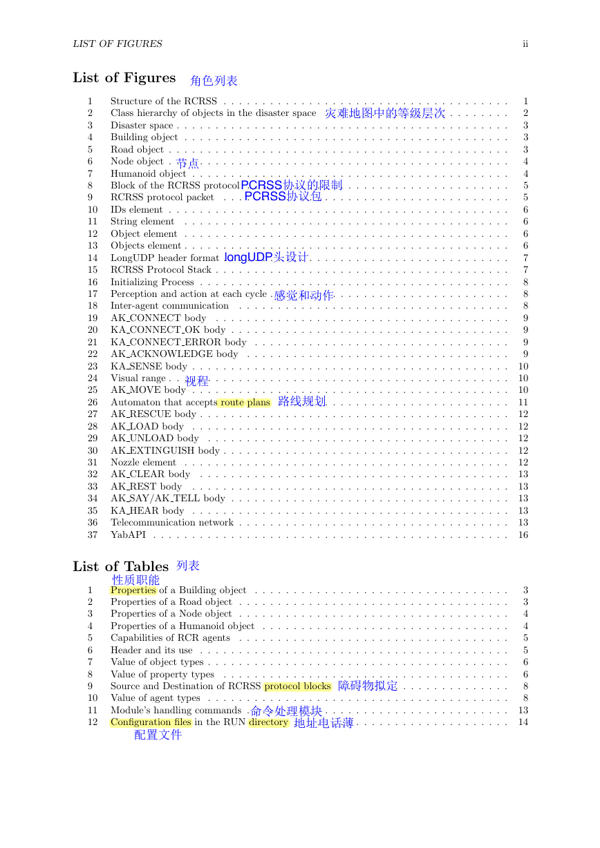
List of Figures
Structure of the RCRSS . . . . . . . . . . . . . . . . . . . . . . . . . . . . . . . . . . . . .
1
Class hierarchy of objects in the disaster space . . . . . . . . . . . . . . . . . . . . . . . .
2
Disaster space . . . . . . . . . . . . . . . . . . . . . . . . . . . . . . . . . . . . . . . . . . .
3
Building object . . . . . . . . . . . . . . . . . . . . . . . . . . . . . . . . . . . . . . . . . .
4
Road object . . . . . . . . . . . . . . . . . . . . . . . . . . . . . . . . . . . . . . . . . . . .
5
Node object . . . . . . . . . . . . . . . . . . . . . . . . . . . . . . . . . . . . . . . . . . . .
6
Humanoid object . . . . . . . . . . . . . . . . . . . . . . . . . . . . . . . . . . . . . . . . .
7
Block of the RCRSS protocol
. . . . . . . . . . . . . . . . . . . . . . . . . . . . . . . . . .
8
RCRSS protocol packet
. . . . . . . . . . . . . . . . . . . . . . . . . . . . . . . . . . . . .
9
IDs element . . . . . . . . . . . . . . . . . . . . . . . . . . . . . . . . . . . . . . . . . . . .
10
11
String element
. . . . . . . . . . . . . . . . . . . . . . . . . . . . . . . . . . . . . . . . . .
12 Object element . . . . . . . . . . . . . . . . . . . . . . . . . . . . . . . . . . . . . . . . . .
13 Objects element . . . . . . . . . . . . . . . . . . . . . . . . . . . . . . . . . . . . . . . . . .
14
LongUDP header format . . . . . . . . . . . . . . . . . . . . . . . . . . . . . . . . . . . . .
15 RCRSS Protocol Stack . . . . . . . . . . . . . . . . . . . . . . . . . . . . . . . . . . . . . .
16
Initializing Process . . . . . . . . . . . . . . . . . . . . . . . . . . . . . . . . . . . . . . . .
17 Perception and action at each cycle . . . . . . . . . . . . . . . . . . . . . . . . . . . . . . .
18
Inter-agent communication . . . . . . . . . . . . . . . . . . . . . . . . . . . . . . . . . . .
19 AK CONNECT body . . . . . . . . . . . . . . . . . . . . . . . . . . . . . . . . . . . . . .
20 KA CONNECT OK body . . . . . . . . . . . . . . . . . . . . . . . . . . . . . . . . . . . .
21 KA CONNECT ERROR body . . . . . . . . . . . . . . . . . . . . . . . . . . . . . . . . .
22 AK ACKNOWLEDGE body . . . . . . . . . . . . . . . . . . . . . . . . . . . . . . . . . .
23 KA SENSE body . . . . . . . . . . . . . . . . . . . . . . . . . . . . . . . . . . . . . . . . .
24 Visual range . . . . . . . . . . . . . . . . . . . . . . . . . . . . . . . . . . . . . . . . . . . .
25 AK MOVE body . . . . . . . . . . . . . . . . . . . . . . . . . . . . . . . . . . . . . . . . .
26 Automaton that accepts route plans
. . . . . . . . . . . . . . . . . . . . . . . . . . . . . .
27 AK RESCUE body . . . . . . . . . . . . . . . . . . . . . . . . . . . . . . . . . . . . . . . .
28 AK LOAD body . . . . . . . . . . . . . . . . . . . . . . . . . . . . . . . . . . . . . . . . .
29 AK UNLOAD body . . . . . . . . . . . . . . . . . . . . . . . . . . . . . . . . . . . . . . .
30 AK EXTINGUISH body . . . . . . . . . . . . . . . . . . . . . . . . . . . . . . . . . . . . .
31 Nozzle element
. . . . . . . . . . . . . . . . . . . . . . . . . . . . . . . . . . . . . . . . . .
32 AK CLEAR body . . . . . . . . . . . . . . . . . . . . . . . . . . . . . . . . . . . . . . . .
33 AK REST body . . . . . . . . . . . . . . . . . . . . . . . . . . . . . . . . . . . . . . . . .
34 AK SAY/AK TELL body . . . . . . . . . . . . . . . . . . . . . . . . . . . . . . . . . . . .
35 KA HEAR body . . . . . . . . . . . . . . . . . . . . . . . . . . . . . . . . . . . . . . . . .
36 Telecommunication network . . . . . . . . . . . . . . . . . . . . . . . . . . . . . . . . . . .
37 YabAPI . . . . . . . . . . . . . . . . . . . . . . . . . . . . . . . . . . . . . . . . . . . . . .
List of Tables
1
Properties of a Building object
. . . . . . . . . . . . . . . . . . . . . . . . . . . . . . . . .
2
Properties of a Road object . . . . . . . . . . . . . . . . . . . . . . . . . . . . . . . . . . .
3
Properties of a Node object . . . . . . . . . . . . . . . . . . . . . . . . . . . . . . . . . . .
4
Properties of a Humanoid object . . . . . . . . . . . . . . . . . . . . . . . . . . . . . . . .
5
Capabilities of RCR agents
. . . . . . . . . . . . . . . . . . . . . . . . . . . . . . . . . . .
6
Header and its use . . . . . . . . . . . . . . . . . . . . . . . . . . . . . . . . . . . . . . . .
7
Value of object types . . . . . . . . . . . . . . . . . . . . . . . . . . . . . . . . . . . . . . .
8
. . . . . . . . . . . . . . . . . . . . . . . . . . . . . . . . . . . . .
Value of property types
9
Source and Destination of RCRSS protocol blocks
. . . . . . . . . . . . . . . . . . . . . .
10 Value of agent types . . . . . . . . . . . . . . . . . . . . . . . . . . . . . . . . . . . . . . .
11 Module’s handling commands . . . . . . . . . . . . . . . . . . . . . . . . . . . . . . . . . .
12 Configuration files in the RUN directory . . . . . . . . . . . . . . . . . . . . . . . . . . . .
ii
1
2
3
3
3
4
4
5
5
6
6
6
6
7
7
8
8
8
9
9
9
9
10
10
10
11
12
12
12
12
12
13
13
13
13
13
16
3
3
4
4
5
5
6
6
8
8
13
14
�
1 INTRODUCTION
1 Introduction
1
This manual is written for computer science/engineering researchers and students to acquire sufficient
knowledge on how to develop a RoboCupRescue agent (RCR agent) without background knowledge on
RoboCupRescue[1].
In the RoboCupRescue simulation, rescue agents such as ambulance teams and fire brigades act in
large urban disasters. Soon after a large earthquake, buildings collapse, many civilians are buried in the
collapsed buildings, fires are spreading, and it becomes difficult for rescue teams to pass roads because
these are blocked by debris of buildings and something else. The objective of rescue agents is, coherently,
to minimize damage resulting from disasters.
The urban area called the disaster space is simulated by the RoboCupRescue Simulation System
(RCRSS). The RCRSS consists of several modules, and the kernel module manages the whole of the
RCRSS. An RCR agent also is one of modules, and communicates with the kernel through a network to
act in the disaster space. Necessary for developing an RCR agent is understanding of the RCRSS, the
disaster space, and the means by which an RCR agent communicates with the kernel.
This manual, at first, describes the RCRSS and the disaster space. Then it describes how an RCR
agent acts in the disaster space by communicating with the kernel. Additionally, it shows how to use
the RCRSS. The appendix contains an explanation of how to develop an RCR agent using the YabAPI,
a bare essential API to develop an RCR agent in JAVA. The reader will be able to develop an original
RCR agent soon, using YabAPI.
In this manual, the RCRSS means the RCRSS version 0.xx unless otherwise noted.
2 RoboCupRescue Simulation System
2.1 Structure
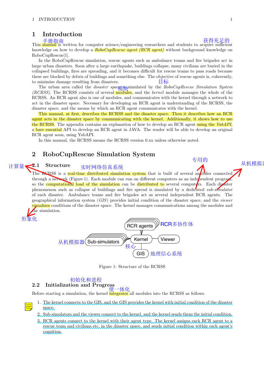
The RCRSS is a real-time distributed simulation system that is built of several modules connected
through a network (Figure 1). Each module can run on different computers as an independent program,
so the computational load of the simulation can be distributed to several computers. Each disaster
phenomenon such as collapse of buildings and fire spread is simulated by a dedicated sub-simulator
of each disaster. Ambulance teams and fire brigades act as several independent RCR agents. The
geographical information system (GIS) provides initial condition of the disaster space, and the viewer
visualizes conditions of the disaster space. The kernel manages communications among the modules and
the simulation.
RCR agents
Sub-simulators
Kernel
Viewer
GIS
Figure 1: Structure of the RCRSS
2.2 Initialization and Progress
Before starting a simulation, the kernel integrates all modules into the RCRSS as follows.
1. The kernel connects to the GIS, and the GIS provides the kernel with initial condition of the disaster
space.
2. Sub-simulators and the viewer connect to the kernel, and the kernel sends them the initial condition.
3. RCR agents connect to the kernel with their agent type. The kernel assigns each RCR agent to a
rescue team and civilians etc. in the disaster space, and sends initial condition within each agent’s
cognition.
�
2 ROBOCUPRESCUE SIMULATION SYSTEM
2
When all rescue teams and civilians in the disaster space have been assigned to RCR agents, the kernel
finishes the integration and the initialization of the RCRSS. Then, the simulation starts. All sub-
simulators and the viewer have to be connected to the kernel before all assignment of an RCR agent have
been finished.
The simulation proceeds by repeating the following cycle. At the first cycle of the simulation, steps
1 and 2 are skipped.
1. The kernel sends individual vision information to each RCR agent.
2. Each RCR agent submits an action command to the kernel individually.
3. The kernel sends action commands of RCR agents to all sub-simulators.
4. Sub-simulators submit updated states of the disaster space to the kernel.
5. The kernel integrates the received states, and sends it to the viewer.
6. The kernel advances the simulation clock of the disaster space.
One cycle in the simulation corresponds to one minute in the disaster space. The kernel waits half a
second for command/state submissions at steps 2 and 4, so it takes one second to simulate one cycle. It
occasionally takes a few seconds according to the scale of simulation and machine specs. All RCR agents
must decide an action within half a second.
The modules of the RCRSS work as follows at the beginning of the simulation.
1st cycle: A collapse sub-simulator simulates building collapse, and a fire sub-simulator starts sim-
ulating fire spread.
2nd cycle: A blockade sub-simulator simulates road blockade based on the result of the collapse
simulator, and a misc (stands for miscellaneous) sub-simulator starts simulating humans who are
buried and injured.
3rd cycle: RCR agents start acting.
2.3 Disaster Space
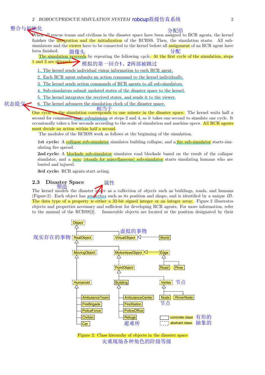
The kernel models the disaster space as a collection of objects such as buildings, roads, and humans
(Figure 2). Each object has properties such as its position and shape, and is identified by a unique ID.
The data type of a property is either a 32-bit signed integer or an integer array. Figure 2 illustrates
objects and properties necessary and sufficient for developing RCR agents. For more information, refer
to the manual of the RCRSS[2].
Immovable objects are located at the position designated by their
Object
RealObject
VirtualObject
World
MovingObject
MotionlessObject
Edge
PointObject
Road
River
Humanoid
Building
Vertex
AmbulanceTeam
AmbulanceCenter
Node
RriverNode
FireBrigade
PoliceForce
Civilian
Car
FireStation
PoliceOffice
Refuge
concrete class
abstract class
Figure 2: Class hierarchy of objects in the disaster space
�
2 ROBOCUPRESCUE SIMULATION SYSTEM
3
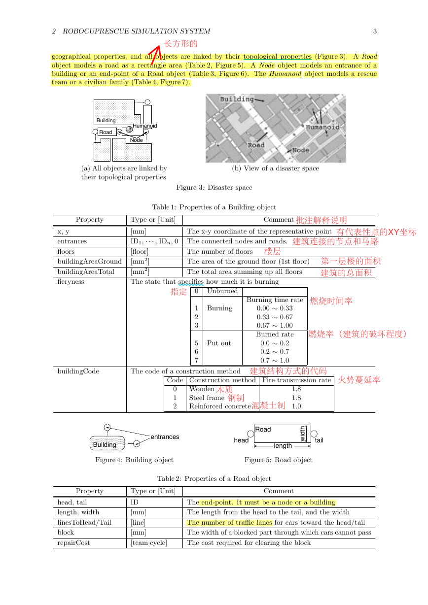
geographical properties, and all objects are linked by their topological properties (Figure 3). A Road
object models a road as a rectangle area (Table 2, Figure 5). A Node object models an entrance of a
building or an end-point of a Road object (Table 3, Figure 6). The Humanoid object models a rescue
team or a civilian family (Table 4, Figure 7).
Building
Road
Humanoid
Node
(a) All objects are linked by
their topological properties
(b) View of a disaster space
Figure 3: Disaster space
Table 1: Properties of a Building object
Property
x, y
entrances
floors
buildingAreaGround
buildingAreaTotal
fieryness
The x-y coordinate of the representative point
Comment
Type or [Unit]
[mm]
ID1, ··· , IDn, 0 The connected nodes and roads.
[floor]
[mm2]
[mm2]
The state that specifies how much it is burning
The number of floors
The area of the ground floor (1st floor)
The total area summing up all floors
0 Unburned
1 Burning
2
3
5 Put out
6
7
Burning time rate
0.00 ∼ 0.33
0.33 ∼ 0.67
0.67 ∼ 1.00
Burned rate
0.0 ∼ 0.2
0.2 ∼ 0.7
0.7 ∼ 1.0
buildingCode
The code of a construction method
Code Construction method Fire transmission rate
0 Wooden
1
2
Steel frame
Reinforced concrete
1.8
1.8
1.0
Building
entrances
Road
head
length
t
h
d
w
i
tail
Figure 4: Building object
Figure 5: Road object
Table 2: Properties of a Road object
Property
head, tail
length, width
linesToHead/Tail
block
repairCost
Type or [Unit]
ID
[mm]
[line]
[mm]
[team·cycle]
Comment
The end-point. It must be a node or a building
The length from the head to the tail, and the width
The number of traffic lanes for cars toward the head/tail
The width of a blocked part through which cars cannot pass
The cost required for clearing the block
�
3 ROBOCUPRESCUE AGENT
4
Table 3: Properties of a Node object
Property
x, y
edges
Type or [Unit]
[mm]
ID1, ··· , IDn, 0 The connected roads and buildings
The x-y coordinate
Comment
Node
Building
Road
edges
tail
Humanoid
position
Road
positionExtra
head
Figure 6: Node object
Figure 7: Humanoid object
Table 4: Properties of a Humanoid object
Property
position
Type or [Unit]
ID
positionExtra
[mm]
hp
damage
buriedness
[health point]
[health point]
[team·cycle]
Comment
An object that the humanoid is on. When the humanoid is
loaded by an ambulance, this is set to the ambulance.
The offset length from the position: a length from the head
when the humanoid is on a road, otherwise it is zero
The health point. The humanoid dies when this becomes
zero
The damage point by which the hp dwindles every cycle.
This becomes zero immediately after the humanoid arrives
at a refuge
The cost required to rescue the humanoid. When this is
greater than zero, the humanoid cannot act.
Every object has a representative point, and the distance between two objects is calculated from
their representative points. A representative point of a Building and a Node object is a point plotted
by the x and y properties. A Road object’s is a midpoint between its head and tail in this regard a
fraction is rounded down. If a Humanoid object is on a Building, Node, or AmbulanceTeam object, the
representative point is the same as that of the object under the Humanoid object. If a Humanoid object
is on a Road object, the representative point is a point positionExtra [mm] away from the head of the
Road object.
3 RoboCupRescue Agent
3.1 Definition
An RCR agent controls act of an object in the disaster space. The object is called a controlled object, and
there are seven classes for it: the Civilian, AmbulanceTeam, FireBrigade, PoliceForce, AmbulanceCenter,
FireStation, and PoliceOffice. An RCR agent controlling act of a Civilian object is called a civilian agent,
an RCR agent controlling act of an AmbulanceTeam object is called an ambulance team agent, and so on.
Additionally, the ambulance team, fire brigade, and police force agent are collectively called a platoon
agent, and the ambulance center, fire station, police office agent are also called a center agent. The
platoon and center agent is called a rescue agent.
Act of an object is processed as repeating cognition of the surrounding circumstances and decision
of an act at each cycle. An RCR agent recognizes the surrounding circumstances based upon vision
information received from the kernel, decides an act, and submits the act to the kernel. Moreover, an
RCR agent communicates with other RCR agents asynchronously (i.e. independently of cycles).
An RCR agent has different capabilities for cognition and act according to its type (Table5). An RCR
agent gets vision information by the sense capability and auditory information by the hear capability,
and acts by the move, rescue, load, unload, extinguish, and clear capabilities, and utters natural voice by
say capability and speak via telecommunication by tell capability.
�
3 ROBOCUPRESCUE AGENT
5
Table 5: Capabilities of RCR agents
Type
Civilian
Ambulance Team
Fire Brigade
Police Force
Ambulance Center
Fire Station
Police Office
Capabilities
Move
Sense, Hear, Say,
Sense, Hear, Say, Tell, Move, Rescue, Load, Unload
Sense, Hear, Say, Tell, Move, Extinguish
Sense, Hear, Say, Tell, Move, Clear
Sense, Hear, Say, Tell
Sense, Hear, Say, Tell
Sense, Hear, Say, Tell
3.2 Protocol of Communication with the Kernel
3.2.1 RCRSS Protocol
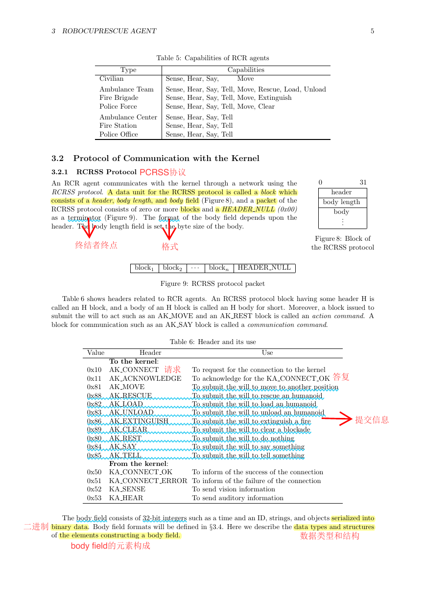
An RCR agent communicates with the kernel through a network using the
RCRSS protocol. A data unit for the RCRSS protocol is called a block which
consists of a header, body length, and body field (Figure 8), and a packet of the
RCRSS protocol consists of zero or more blocks and a HEADER NULL (0x00)
as a terminator (Figure 9). The format of the body field depends upon the
header. The body length field is set the byte size of the body.
0
31
header
body length
body
...
Figure 8: Block of
the RCRSS protocol
block1
block2
···
blockn HEADER NULL
Figure 9: RCRSS protocol packet
Table 6 shows headers related to RCR agents. An RCRSS protocol block having some header H is
called an H block, and a body of an H block is called an H body for short. Moreover, a block issued to
submit the will to act such as an AK MOVE and an AK REST block is called an action command. A
block for communication such as an AK SAY block is called a communication command.
Table 6: Header and its use
Value
Header
To the kernel:
0x10 AK CONNECT
0x11 AK ACKNOWLEDGE
0x81 AK MOVE
0x88 AK RESCUE
0x82 AK LOAD
0x83 AK UNLOAD
0x86 AK EXTINGUISH
0x89 AK CLEAR
0x80 AK REST
0x84 AK SAY
0x85 AK TELL
Use
To request for the connection to the kernel
To acknowledge for the KA CONNECT OK
To submit the will to move to another position
To submit the will to rescue an humanoid
To submit the will to load an humanoid
To submit the will to unload an humanoid
To submit the will to extinguish a fire
To submit the will to clear a blockade
To submit the will to do nothing
To submit the will to say something
To submit the will to tell something
From the kernel:
0x50 KA CONNECT OK
To inform of the success of the connection
0x51 KA CONNECT ERROR To inform of the failure of the connection
0x52 KA SENSE
0x53 KA HEAR
To send vision information
To send auditory information
The body field consists of 32-bit integers such as a time and an ID, strings, and objects serialized into
binary data. Body field formats will be defined in §3.4. Here we describe the data types and structures
of the elements constructing a body field.
�



 2023年江西萍乡中考道德与法治真题及答案.doc
 2012年重庆南川中考生物真题及答案.doc
 2013年江西师范大学地理学综合及文艺理论基础考研真题.doc
 2020年四川甘孜小升初语文真题及答案I卷.doc
 2020年注册岩土工程师专业基础考试真题及答案.doc
 2023-2024学年福建省厦门市九年级上学期数学月考试题及答案.doc
 2021-2022学年辽宁省沈阳市大东区九年级上学期语文期末试题及答案.doc
 2022-2023学年北京东城区初三第一学期物理期末试卷及答案.doc
 2018上半年江西教师资格初中地理学科知识与教学能力真题及答案.doc
 2012年河北国家公务员申论考试真题及答案-省级.doc
 2020-2021学年江苏省扬州市江都区邵樊片九年级上学期数学第一次质量检测试题及答案.doc
 2022下半年黑龙江教师资格证中学综合素质真题及答案.doc