Datasheet SHT3x-DIS
Humidity and Temperature Sensor
Fully calibrated,
linearized, and
temperature
compensated digital output
Wide supply voltage range, from 2.4 V to 5.5 V
I2C Interface with communication speeds up to 1
MHz and two user selectable addresses
Typical accuracy of 1.5 %RH and 0.1 °C for
SHT35
Very fast start-up and measurement time
Tiny 8-Pin DFN package
Product Summary
is
SHT3x-DIS
the next generation of Sensirion’s
temperature and humidity sensors. It builds on a new
CMOSens® sensor chip that is at the heart of Sensirion’s
new humidity and temperature platform. The SHT3x-DIS
has increased intelligence, reliability and improved
accuracy specifications compared to its predecessor. Its
functionality includes enhanced signal processing, two
distinctive and user selectable I2C addresses and
communication speeds of up to 1 MHz. The DFN
Benefits of Sensirion’s CMOSens® Technology
High reliability and long-term stability
Industry-proven technology with a track record of
more than 15 years
Designed for mass production
High process capability
High signal-to-noise ratio
Content
1
Sensor Performance............................................. 2
2
3
4
5
6
7
8
Specifications ....................................................... 6
Pin Assignment .................................................... 8
Operation and Communication ............................. 9
Packaging ........................................................... 15
Shipping Package .............................................. 17
Quality ................................................................ 18
Ordering Information........................................... 18
package has a footprint of 2.5 x 2.5 mm2 while keeping
a height of 0.9 mm. This allows for integration of the
SHT3x-DIS
into a great variety of applications.
Additionally, the wide supply voltage range of 2.4 V to
5.5 V guarantees compatibility with diverse assembly
situations. All in all, the SHT3x-DIS incorporates 15
years of knowledge of Sensirion, the leader in the
humidity sensor industry.
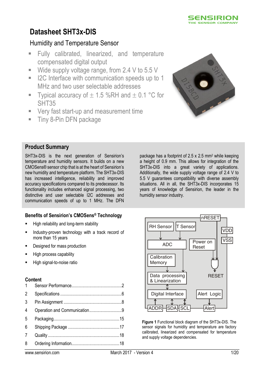
Figure 1 Functional block diagram of the SHT3x-DIS. The
sensor signals for humidity and temperature are factory
calibrated, linearized and compensated for temperature
and supply voltage dependencies.
www.sensirion.com
March 2017 - Version 4
1/20
nRESETAlertSDASCLADDRPower on ResetAlert LogicRESETDigital InterfaceRH SensorT SensorData processing& LinearizationADCADCCalibration MemoryVSSVDDVSSVDD�
Condition
Typ.
Max.
Typ.
Max.
Typ.
Max.
Low
Medium
High
Typ.
at 25°C
extended4
63%
Typ.7
Value
2
Figure 2
2
Figure 3
±1.5
Figure 4
0.25
0.15
0.10
0.01
0.8
0 to 100
86
<0.25
Units
%RH
-
%RH
-
%RH
-
%RH
%RH
%RH
%RH
%RH
%RH
s
%RH/yr
Condition
Value
Units
typ., 0°C to 65°C
typ., 0°C to 90°C
typ., 20°C to 60°C
Low
Medium
High
Typ.
-
63%
max
0.2
0.2
±0.1
0.24
0.12
0.06
0.015
-40 to 125
>2
<0.03
°C
°C
°C
°C
°C
°C
°C
°C
s
°C/yr
Datasheet SHT3x-DIS
1 Sensor Performance
Humidity Sensor Specification
Parameter
SHT30 Accuracy tolerance1
SHT31 Accuracy tolerance1
SHT35 Accuracy tolerance1
Repeatability2
Resolution
Hysteresis
Specified range3
Response time5
Long-term drift
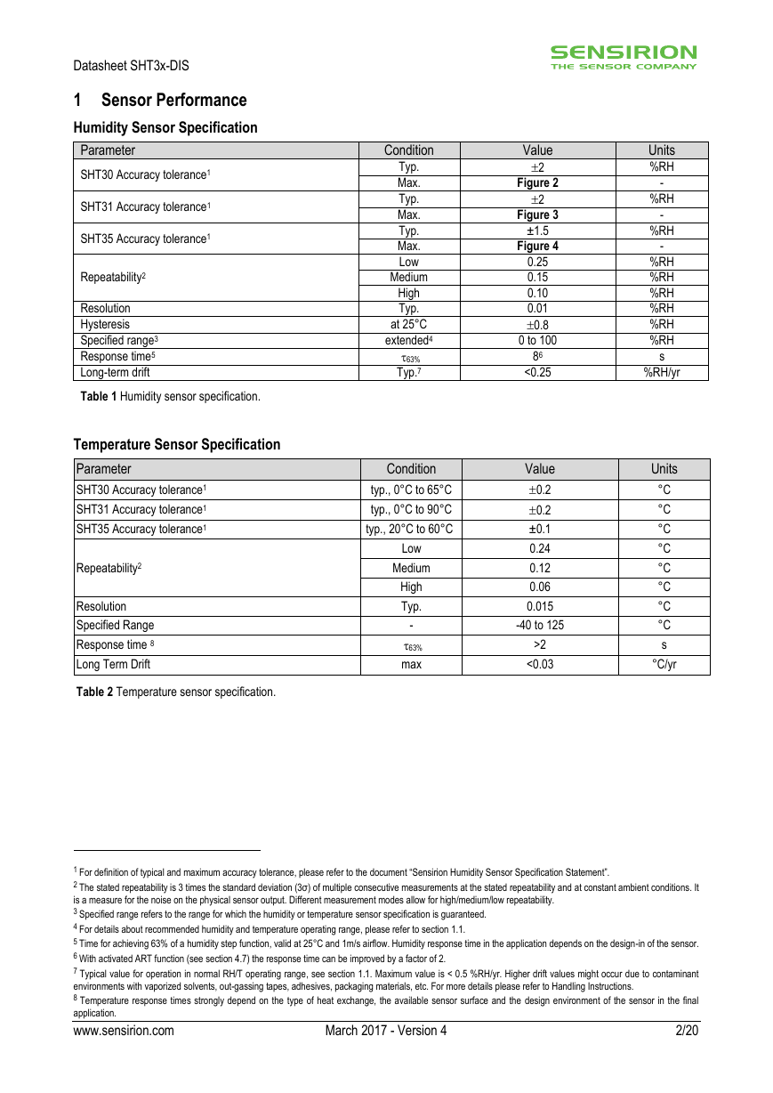
Table 1 Humidity sensor specification.
Temperature Sensor Specification
Parameter
SHT30 Accuracy tolerance1
SHT31 Accuracy tolerance1
SHT35 Accuracy tolerance1
Repeatability2
Resolution
Specified Range
Response time 8
Long Term Drift
Table 2 Temperature sensor specification.
1 For definition of typical and maximum accuracy tolerance, please refer to the document “Sensirion Humidity Sensor Specification Statement”.
2 The stated repeatability is 3 times the standard deviation (3σ) of multiple consecutive measurements at the stated repeatability and at constant ambient conditions. It
is a measure for the noise on the physical sensor output. Different measurement modes allow for high/medium/low repeatability.
3 Specified range refers to the range for which the humidity or temperature sensor specification is guaranteed.
4 For details about recommended humidity and temperature operating range, please refer to section 1.1.
5 Time for achieving 63% of a humidity step function, valid at 25°C and 1m/s airflow. Humidity response time in the application depends on the design-in of the sensor.
6 With activated ART function (see section 4.7) the response time can be improved by a factor of 2.
7 Typical value for operation in normal RH/T operating range, see section 1.1. Maximum value is < 0.5 %RH/yr. Higher drift values might occur due to contaminant
environments with vaporized solvents, out-gassing tapes, adhesives, packaging materials, etc. For more details please refer to Handling Instructions.
8 Temperature response times strongly depend on the type of heat exchange, the available sensor surface and the design environment of the sensor in the final
application.
www.sensirion.com
March 2017 - Version 4
2/20
�
Datasheet SHT3x-DIS
Humidity Sensor Performance Graphs
DRH (%RH)
maximal tolerance
typical tolerance
±8
±6
±4
±2
±0
DRH (%RH)
maximal tolerance
typical tolerance
±8
±6
±4
±2
±0
0
10
20
30
40
50
60
70
80
90
100
0
10
20
30
40
50
SHT30
Relative Humidity (%RH)
SHT31
70
60
100
Relative Humidity (%RH)
80
90
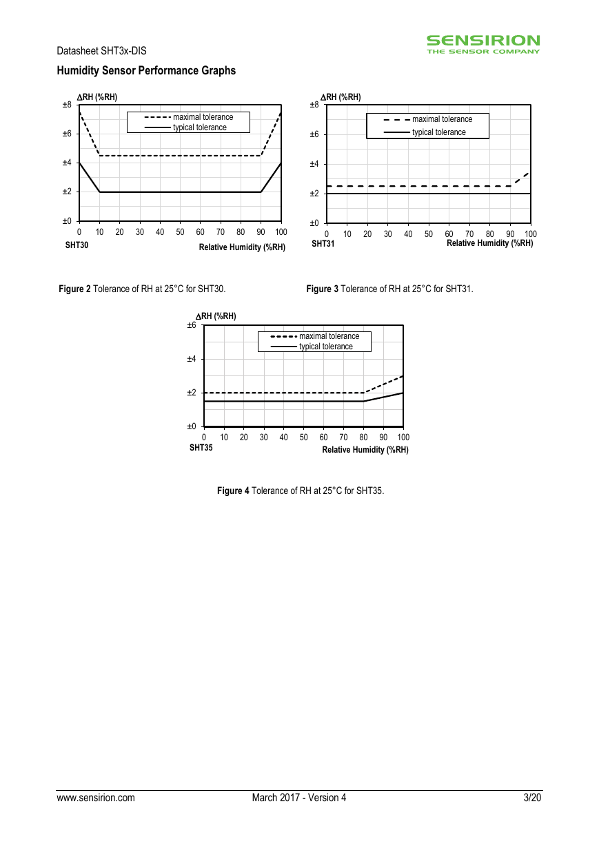
Figure 2 Tolerance of RH at 25°C for SHT30.
Figure 3 Tolerance of RH at 25°C for SHT31.
maximal tolerance
typical tolerance
DRH (%RH)
±6
±4
±2
±0
0
10
20
30
40
50
SHT35
70
60
100
Relative Humidity (%RH)
80
90
Figure 4 Tolerance of RH at 25°C for SHT35.
www.sensirion.com
March 2017 - Version 4
3/20
�
Datasheet SHT3x-DIS
SHT30
SHT31
RH (%RH)
100
90
80
70
60
50
40
30
20
10
0
0
±4 ±4 ±4 ±4 ±4 ±4 ±4 ±4
±3 ±3 ±3 ±3 ±3 ±3 ±3 ±3
±2 ±2 ±2 ±2 ±2 ±2 ±2 ±2
±2 ±2 ±2 ±2 ±2 ±2 ±2 ±2
±2 ±2 ±2 ±3 ±2 ±2 ±2 ±2
±2 ±2 ±2 ±2 ±2 ±2 ±2 ±2
±2 ±2 ±2 ±2 ±2 ±2 ±2 ±2
±2 ±2 ±2 ±2 ±2 ±2 ±2 ±2
±2 ±2 ±2 ±2 ±2 ±2 ±2 ±2
±3 ±3 ±3 ±3 ±3 ±3 ±3 ±3
±4 ±4 ±4 ±4 ±4 ±4 ±4 ±4
10
80
30
70
20
40
50
60
RH (%RH)
100 ±2
90 ±2
80 ±2
70 ±2
60 ±2
50 ±2
40 ±2
30 ±2
20 ±2
10 ±2
0 ±2
0
±2
±2
±2
±2
±2
±2
±2
±2
±2
±2
±2
10
±2
±2
±2
±2
±2
±2
±2
±2
±2
±2
±2
20
±2
±2
±2
±2
±2
±2
±2
±2
±2
±2
±2
30
±2
±2
±2
±2
±2
±2
±2
±2
±2
±2
±2
40
±2
±2
±2
±2
±2
±2
±2
±2
±2
±2
±2
50
±2
±2
±2
±2
±2
±2
±2
±2
±2
±2
±2
60
±2
±2
±2
±2
±2
±2
±2
±2
±2
±2
±2
70
±2
±2
±2
±2
±2
±2
±2
±2
±2
±2
±2
80
Temperature (°C)
Temperature (°C)
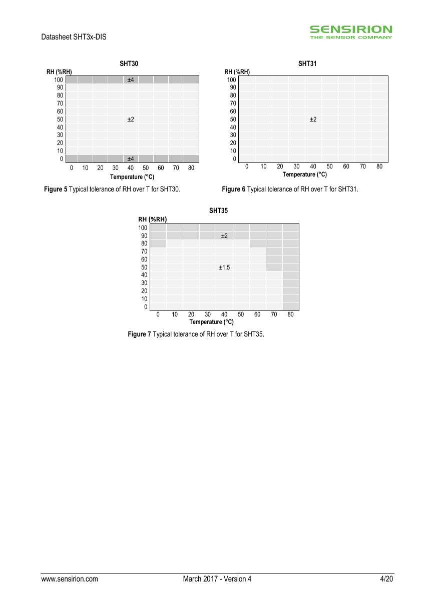
Figure 5 Typical tolerance of RH over T for SHT30.
Figure 6 Typical tolerance of RH over T for SHT31.
SHT35
±2
±2
±2
±2
±2
±2
±2
±2
±2
±2
±2
±2
±2
RH (%RH)
±2
100 ±2
±2
±2
90 ±2
±2
±2
80 ±2
±2
±2
70 ±1.5 ±1.5 ±1.5 ±1.5 ±1.5 ±1.5 ±1.5 ±2
±2
60 ±1.5 ±1.5 ±1.5 ±1.5 ±1.5 ±1.5 ±1.5 ±2
50 ±1.5 ±1.5 ±1.5 ±1.5 ±1.5 ±1.5 ±1.5 ±2
±2
40 ±1.5 ±1.5 ±1.5 ±1.5 ±1.5 ±1.5 ±1.5 ±1.5 ±2
30 ±1.5 ±1.5 ±1.5 ±1.5 ±1.5 ±1.5 ±1.5 ±1.5 ±2
20 ±1.5 ±1.5 ±1.5 ±1.5 ±1.5 ±1.5 ±1.5 ±1.5 ±2
10 ±1.5 ±1.5 ±1.5 ±1.5 ±1.5 ±1.5 ±1.5 ±1.5 ±2
0 ±1.5 ±1.5 ±1.5 ±1.5 ±1.5 ±1.5 ±1.5 ±1.5 ±2
80
70
10
0
50
60
30
20
Temperature (°C)
40
Figure 7 Typical tolerance of RH over T for SHT35.
www.sensirion.com
March 2017 - Version 4
4/20
�
Datasheet SHT3x-DIS
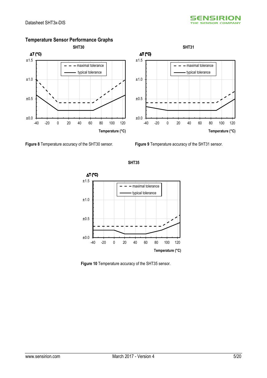
Temperature Sensor Performance Graphs
SHT30
SHT31
DT (°C)
DT (°C)
DT (°C)
DT (°C)
DT (°C)
DT (°C)
±1.5
±1.0
±0.5
±0.0
maximal tolerance
typical tolerance
DT (°C)
DT (°C)
DT (°C)
DT (°C)
DT (°C)
DT (°C)
DT (°C)
DT (°C)
DT (°C)
DT (°C)
DT (°C)
DT (°C)
DT (°C)
DT (°C)
DT (°C)
DT (°C)
DT (°C)
DT (°C)
DT (°C)
DT (°C)
DT (°C)
DT (°C)
DT (°C)
DT (°C)
DT (°C)
DT (°C)
DT (°C)
DT (°C)
DT (°C)
DT (°C)
DT (°C)
DT (°C)
DT (°C)
DT (°C)
DT (°C)
DT (°C)
DT (°C)
DT (°C)
DT (°C)
DT (°C)
DT (°C)
DT (°C)
DT (°C)
DT (°C)
DT (°C)
DT (°C)
DT (°C)
DT (°C)
DT (°C)
DT (°C)
DT (°C)
DT (°C)
DT (°C)
DT (°C)
±1.5
±1.0
±0.5
±0.0
maximal tolerance
typical tolerance
-40
-20
0
20
40
60
80
100
120
-40
-20
0
20
40
60
80
100
120
Temperature (°C)
Figure 8 Temperature accuracy of the SHT30 sensor.
Figure 9 Temperature accuracy of the SHT31 sensor.
Temperature (°C)
SHT35
maximal tolerance
typical tolerance
DT (°C)
DT (°C)
DT (°C)
DT (°C)
DT (°C)
DT (°C)
DT (°C)
DT (°C)
DT (°C)
DT (°C)
DT (°C)
DT (°C)
DT (°C)
DT (°C)
DT (°C)
DT (°C)
DT (°C)
DT (°C)
±1.5
±1.0
±0.5
±0.0
-40
-20
0
20
40
60
80
100
120
Temperature (°C)
Figure 10 Temperature accuracy of the SHT35 sensor.
www.sensirion.com
March 2017 - Version 4
5/20
�
Datasheet SHT3x-DIS
1.1 Recommended Operating Condition
The sensor shows best performance when operated within recommended normal temperature and humidity range of 5 °C
– 60 °C and 20 %RH – 80 %RH, respectively. Long-term exposure to conditions outside normal range, especially at high
humidity, may temporarily offset the RH signal (e.g. +3%RH after 60h kept at >80%RH). After returning into the normal
temperature and humidity range the sensor will slowly come back to calibration state by itself. Prolonged exposure to
extreme conditions may accelerate ageing. To ensure stable operation of the humidity sensor, the conditions described in
the document “SHTxx Assembly of SMD Packages”, section “Storage and Handling Instructions” regarding exposure to
volatile organic compounds have to be met. Please note as well that this does apply not only to transportation and
manufacturing, but also to operation of the SHT3x-DIS.
2 Specifications
2.1 Electrical Specifications
Parameter
Symbol
Condition
Min.
Typ.
Max.
Units Comments
Supply voltage
Power-up/down level
VDD
VPOR
Slew rate change of the
supply voltage
VDD,slew
Supply current
IDD
idle state
(single shot mode)
idle state
(periodic data
acquisition mode)
Measuring
Average
2.4
2.1
3.3
2.3
5.5
2.4
V
V
-
-
-
-
-
-
20
V/ms
0.2
2.0
A
45
-
A
800
1500
A
2
-
A
Voltage changes on the
VDD line between
VDD,min and VDD,max
should be slower than
the maximum slew rate;
faster slew rates may
lead to reset;
Current when sensor is
not performing a
measurement during
single shot mode
Current when sensor is
not performing a
measurement during
periodic data acquisition
mode
Current consumption
while sensor is
measuring
Current consumption
(operation with one
measurement per
second at lowest
repeatability, single shot
mode)
Alert Output driving
strength
IOH
1.5x VDD
mA See also section 3.5
Heater power
PHeater
Heater running
4.5
-
33
mW
Depending on the
supply voltage
Table 3 Electrical specifications, valid at 25°C.
www.sensirion.com
March 2017 - Version 4
6/20
�
Datasheet SHT3x-DIS
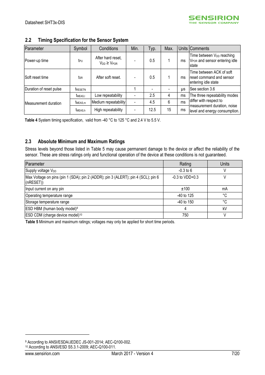
2.2 Timing Specification for the Sensor System
Parameter
Symbol
Conditions
Min.
Typ.
Max. Units Comments
Power-up time
tPU
After hard reset,
VDD ≥ VPOR
Soft reset time
tSR
After soft reset.
Duration of reset pulse
tRESETN
tMEAS,l
Low repeatability
Measurement duration
tMEAS,m Medium repeatability
tMEAS,h
High repeatability
-
-
1
-
-
-
0.5
0.5
-
2.5
4.5
1
1
-
4
6
12.5
15
ms
ms
Time between VDD reaching
VPOR and sensor entering idle
state
Time between ACK of soft
reset command and sensor
entering idle state
µs See section 3.6
ms The three repeatability modes
ms
ms
differ with respect to
measurement duration, noise
level and energy consumption.
Table 4 System timing specification, valid from -40 °C to 125 °C and 2.4 V to 5.5 V.
2.3 Absolute Minimum and Maximum Ratings
Stress levels beyond those listed in Table 5 may cause permanent damage to the device or affect the reliability of the
sensor. These are stress ratings only and functional operation of the device at these conditions is not guaranteed.
Parameter
Supply voltage VDD
Max Voltage on pins (pin 1 (SDA); pin 2 (ADDR); pin 3 (ALERT); pin 4 (SCL); pin 6
(nRESET))
Input current on any pin
Operating temperature range
Storage temperature range
ESD HBM (human body model)9
ESD CDM (charge device model)10
Rating
-0.3 to 6
-0.3 to VDD+0.3
±100
-40 to 125
-40 to 150
4
750
Units
V
V
mA
°C
°C
kV
V
Table 5 Minimum and maximum ratings; voltages may only be applied for short time periods.
9 According to ANSI/ESDA/JEDEC JS-001-2014; AEC-Q100-002.
10 According to ANSI/ESD S5.3.1-2009; AEC-Q100-011.
www.sensirion.com
March 2017 - Version 4
7/20
�
Datasheet SHT3x-DIS
3
Pin Assignment
The SHT3x-DIS comes in a tiny 8-pin DFN package –
see Table 6.
Pin
1
2
3
4
5
Name
SDA
ADDR
ALERT
SCL
VDD
6
nRESET
Comments
Serial data; input / output
Address pin; input; connect to either
logic high or low, do not leave floating
Indicates alarm condition; output; must
be left floating if unused
Serial clock; input / output
Supply voltage; input
Reset pin active low; input; if not used it
is recommended to be left floating; can
be connected to VDD with a series
resistor of R ≥2 kΩ
7
8
R
No electrical function; to be connected
to VSS
VSS
Ground
Communication frequencies up to 1 Mhz are supported
following the specifications given in Table 20.
Both SCL and SDA lines are open-drain I/Os with diodes
to VDD and VSS. They should be connected to external
pull-up resistors (please refer to Figure 11). A device on
the I2C bus must only drive a line to ground. The external
pull-up resistors (e.g. Rp=10 kΩ) are required to pull the
signal high. For dimensioning resistor sizes please take
bus capacity and communication frequency into account
(see for example Section 7.1 of NXPs I2C Manual for
more details11). It should be noted that pull-up resistors
may be included in I/O circuits of microcontrollers. It is
recommended to wire the sensor according to the
application circuit as shown in Figure 11.
Figure 11 Typical application circuit. Please note that the
positioning of the pins does not reflect the position on the
real sensor. This is shown in Table 6.
Table 6 SHT3x-DIS pin assignment (transparent top view).
Dashed lines are only visible if viewed from below. The die
pad is internally connected to VSS.
3.1 Power Pins (VDD, VSS)
The electrical specifications of the SHT3x-DIS are shown
in Table 3. The power supply pins must be decoupled
with a 100 nF capacitor that shall be placed as close to
the sensor as possible – see Figure 11 for a typical
application circuit.
3.2 Serial Clock and Serial Data (SCL, SDA)
SCL is used to synchronize the communication between
microcontroller and the sensor. The clock frequency can
be freely chosen between 0 to 1000 kHz. Commands
with clock stretching according to I2C Standard11 are
supported.
The SDA pin is used to transfer data to and from the
sensor. Communication with frequencies up to 400 kHz
must meet
standard.
I2C Fast Mode11
the
3.3 Die Pad (center pad)
The die pad or center pad is visible from below and
located in the center of the package. It is electrically
connected to VSS. Hence electrical considerations do
not impose constraints on the wiring of the die pad.
However, due to mechanical reasons it is recommended
to solder the center pad to the PCB. For more
information on design-in, please refer to the document
“SHTxx Design Guide”.
3.4 ADDR Pin
Through the appropriate wiring of the ADDR pin the I2C
address can be selected (see Table 7 for the respective
addresses). The ADDR pin can either be connected to
logic high or logic low. The address of the sensor can be
changed dynamically during operation by switching the
level on the ADDR pin. The only constraint is that the
level has to stay constant starting from the I2C start
condition until the communication is finished. This allows
to connect more than two SHT3x-DIS onto the same bus.
11 http://www.nxp.com/documents/user_manual/UM10204.pdf
www.sensirion.com
March 2017 - Version 4
8/20
12345876VDDRRPP100nFADDR(2)ALERT(3)die padR(7)SDA(1)SCL(4)VDD(5)VSS(8)nRESET(6)�



 2023年江西萍乡中考道德与法治真题及答案.doc
 2012年重庆南川中考生物真题及答案.doc
 2013年江西师范大学地理学综合及文艺理论基础考研真题.doc
 2020年四川甘孜小升初语文真题及答案I卷.doc
 2020年注册岩土工程师专业基础考试真题及答案.doc
 2023-2024学年福建省厦门市九年级上学期数学月考试题及答案.doc
 2021-2022学年辽宁省沈阳市大东区九年级上学期语文期末试题及答案.doc
 2022-2023学年北京东城区初三第一学期物理期末试卷及答案.doc
 2018上半年江西教师资格初中地理学科知识与教学能力真题及答案.doc
 2012年河北国家公务员申论考试真题及答案-省级.doc
 2020-2021学年江苏省扬州市江都区邵樊片九年级上学期数学第一次质量检测试题及答案.doc
 2022下半年黑龙江教师资格证中学综合素质真题及答案.doc