A CANopen Stack for PIC18 ECANTM Microcontrollers
AN945
OVERVIEW OF THE STACK
The CANopen Stack provides the lower layers of the
protocol. Some of the features of this design include:
Embedded state machine for handling all
communications between all nodes and objects
Default Service Data Object (SDO) Server
Up to 4 transmit and 4 receive Process Data
Objects (TPDOs and RPDOs)
Explicit and Segmented Messaging Support
Statically-mapped PDO support
Structured dictionary for the PDOs and SDO
Node Guard/Life Guard
SYNC consumer
Heartbeat Producer
ECAN Driver support
As this list shows, the CANopen Stack discussed here
is designed for applications that are typically more
“slave”. This design is more static in nature, which
leads to more efficient code with better effective use of
code space.
In addition, the actual CANopen code is broken into a
series of smaller source and header files, all written in
C. This allows users to select the appropriate services
that they may need for their application and selectively
build a project tailored to their specific requirements. A
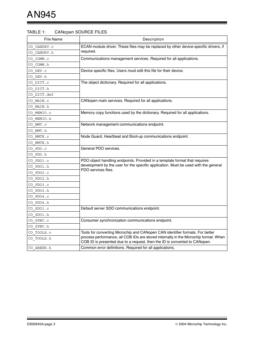
complete list of source files is presented in Table 1.
Of course, the actual application and some aspects of
the communications must still be developed by the
user. The provided CANopen Stack code affords a
base on which the application may be built.
Author:
Ross M. Fosler
Microchip Technology Incorporated
INTRODUCTION
CANopen is a field bus protocol based on the Control-
ler Area Network (CAN). As the name implies, it is a
open network standard accepted throughout the world.
While created as a field bus protocol for industrial
automation, CANopen finds use in a wide range of
other non-industrial applications. There are so many
possibilities, in fact, that it is possible to write volumes
on specialized uses of the protocol.
Rather than being specific to one narrow application or
even one field, we present here a more generalized
approach: a generic communication stack based on
CANopen that can be tailored to the user’s needs. This
article focuses only on what is covered in the CAN in
Automation (CiA) standard DS-301. In fact, most of the
discussion is limited to the predefined areas of the
specification, with emphasis on understanding how the
code provided with this application note functions and
how users might develop an application on the
CANopen Stack. To help illustrate this, a simple exam-
ple application is developed based on the CiA DS-401
specification, Generic I/O Modules. The additional
code provided is solely for demonstration; thus there is
no detailed discussion of the demonstration code.
However, code examples with comments from the
demo application are frequently used throughout this
document.
All code provided with
is
developed for the PIC18F8680 and PIC18F4680
families of devices, which include ECAN technology as
part of their peripheral set. It is designed to compile with
Microchip’s C18 v2.30 (or greater) compiler. Although
developed for these specific device families, the code
is adaptable to other PIC18 families with CAN.
It is expected that the reader already has some
knowledge of CANopen, or has access to the latest
CANopen standard (listed in the References section) to
refer to for theory and/or critical terminology. The infor-
mation covered in this application note leans towards
understanding the implementation and developing on
that foundation, rather than discussing the many details
of CANopen.
this application note
2004 Microchip Technology Inc.
DS00945A-page 1
�
AN945
TABLE 1:
CANopen SOURCE FILES
File Name
Description
CO_CANDRV.c
CO_CANDRV.h
CO_COMM.c
CO_COMM.h
CO_DEV.c
CO_DEV.h
CO_DICT.c
CO_DICT.h
CO_DICT.def
CO_MAIN.c
CO_MAIN.h
CO_MEMIO.c
CO_MEMIO.h
CO_NMT.c
CO_NMT.h
CO_NMTE.c
CO_NMTE.h
CO_PDO.c
CO_PDO.h
CO_PDO1.c
CO_PDO1.h
CO_PDO2.c
CO_PDO2.h
CO_PDO3.c
CO_PDO3.h
CO_PDO4.c
CO_PDO4.h
CO_SDO1.c
CO_SDO1.h
CO_SYNC.c
CO_SYNC.h
CO_TOOLS.c
CO_TOOLS.h
CO_ABERR.h
ECAN module driver. These files may be replaced by other device-specific drivers, if
required.
Communications management services. Required for all applications.
Device specific files. Users must edit this file for their device.
The object dictionary. Required for all applications.
CANopen main services. Required for all applications.
Memory copy functions used by the dictionary. Required for all applications.
Network management communications endpoint.
Node Guard, Heartbeat and Boot-up communications endpoint.
General PDO services.
PDO object handling endpoints. Provided in a template format that requires
development by the user for the specific application. Must be used with the general
PDO services files.
Default server SDO communications endpoint.
Consumer synchronization communications endpoint.
Tools for converting Microchip and CANopen CAN identifier formats. For better
process performance, all COB IDs are stored internally in the Microchip format. When
COB ID is presented due to a request, then the ID is converted to CANopen.
Common error definitions. Required for all applications.
DS00945A-page 2
2004 Microchip Technology Inc.
�
CANopen FIRMWARE MODEL
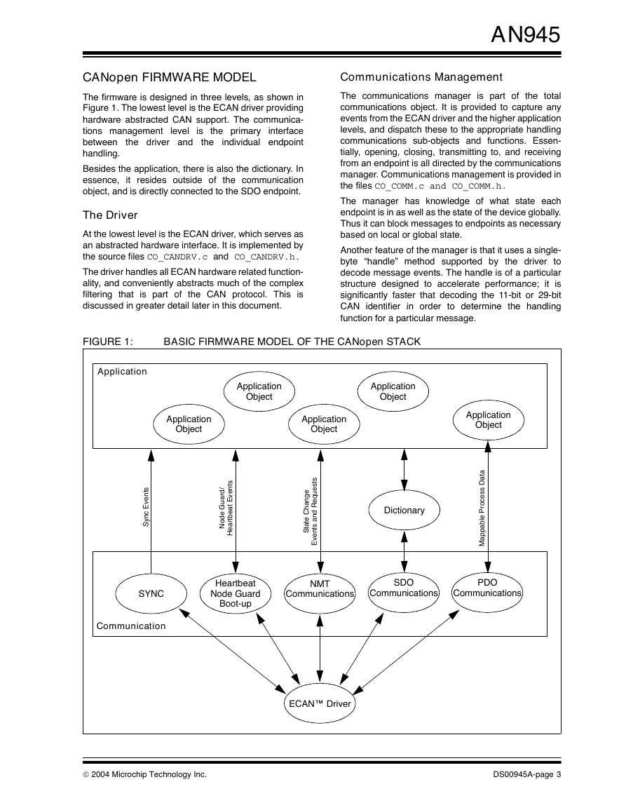
The firmware is designed in three levels, as shown in
Figure 1. The lowest level is the ECAN driver providing
hardware abstracted CAN support. The communica-
tions management level is the primary interface
between
individual endpoint
handling.
Besides the application, there is also the dictionary. In
essence, it resides outside of the communication
object, and is directly connected to the SDO endpoint.
the driver and
the
The Driver
At the lowest level is the ECAN driver, which serves as
an abstracted hardware interface. It is implemented by
the source files CO_CANDRV.c and CO_CANDRV.h.
The driver handles all ECAN hardware related function-
ality, and conveniently abstracts much of the complex
filtering that is part of the CAN protocol. This is
discussed in greater detail later in this document.
AN945
Communications Management
The communications manager is part of the total
communications object. It is provided to capture any
events from the ECAN driver and the higher application
levels, and dispatch these to the appropriate handling
communications sub-objects and functions. Essen-
tially, opening, closing, transmitting to, and receiving
from an endpoint is all directed by the communications
manager. Communications management is provided in
the files CO_COMM.c and CO_COMM.h.
The manager has knowledge of what state each
endpoint is in as well as the state of the device globally.
Thus it can block messages to endpoints as necessary
based on local or global state.
Another feature of the manager is that it uses a single-
byte “handle” method supported by the driver to
decode message events. The handle is of a particular
structure designed to accelerate performance; it is
significantly faster that decoding the 11-bit or 29-bit
CAN identifier in order to determine the handling
function for a particular message.
FIGURE 1:
BASIC FIRMWARE MODEL OF THE CANopen STACK
Application
s
t
n
e
v
E
c
n
y
S
SYNC
Communication
Application
Object
Application
Object
Application
Object
Application
Object
Application
Object
/
d
r
a
u
G
e
d
o
N
s
t
n
e
v
E
t
a
e
b
t
r
a
e
H
e
g
n
a
h
C
e
t
a
t
S
s
t
s
e
u
q
e
R
d
n
a
s
t
n
e
v
E
Dictionary
a
t
a
D
s
s
e
c
o
r
P
e
b
a
p
p
a
M
l
Heartbeat
Node Guard
Boot-up
NMT
Communications
SDO
Communications
PDO
Communications
ECAN™ Driver
2004 Microchip Technology Inc.
DS00945A-page 3
�
AN945
Endpoints
The CANopen specification defines several possible
endpoints. The five endpoint objects listed below are
implemented in this example; others may be made
available in the future.
The Default Server SDO
Up to four Static PDOs
Synchronization Consumer
Network Management Slave
Node Guard or Heartbeat
SERVER SDO COMMUNICATION
The default server SDO (Service Data Object) is
provided. The SDO communications path is directly
linked to the object dictionary; SDO messages contain
information that relates the SDO to a particular object.
Data in every message is decoded, validated, and (if
valid) eventually executed.
There are essentially two basic operations: read and
write. Thus each complete SDO transfer (which may be
multiple messages) will either read or write a single
object referenced in the dictionary. The default SDO is
contained in the source files CO_SDO1.c and
CO_SDO1.h.
PDO COMMUNICATION
The PDO (Process Data Object) communications path
is linked directly to the applicable application object or
objects. Thus the path is assumed by the device and no
path information is contained within the communica-
tion. Essentially the data is mapped internally to one or
more objects. Data is either statically mapped (com-
piled) or dynamically mapped (set at runtime). One
message can contain data from more than one object.
The firmware provided with this application note
supports the four default PDOs. Overall PDO services
are provided in the source files CO_PDO.c and
CO_PDO.h. The additional files CO_PDOn.c and
CO_PDOn.h (where n may have a value of 1 to 4) are
used to implement the individual PDOs. These are
provided in template form, and must be developed to
meet the application requirements.
NETWORK MANAGEMENT CONSUMER
A Network Management (NMT) slave is provided as
required by the specification. The NMT Object receives
commands to change the state of the device or reset
the device’s application and/or communications.
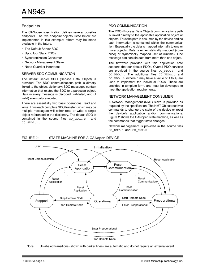
Figure 2 shows the CANopen state machine, as well as
the commands that trigger state changes.
Network management is provided in the source files
CO_NMT.c and CO_NMT.h.
FIGURE 2:
STATE MACHINE FOR A CANopen DEVICE
Start
Initialization
Reset Communication
Reset Application
Reset
Application
Reset
Communication
Reset
Application
Reset
Communication
Reset
Application
Reset
Communication
Stopped
Stop Remote Node
Start Remote Node
Operational
Start Remote Node
Enter Preoperational
Preoperational
Enter Preoperational
Stop Remote Node
Note:
Unlabeled transitions (shown with darker lines) are automatic and do not require an external event.
DS00945A-page 4
2004 Microchip Technology Inc.
�
AN945
By using the index, any defined object can be
accessed. From the network point of view, access to an
object is provided through the SDO or PDO endpoint as
shown in Figure 1. CANopen dictionary functionality is
implemented with these files:
CO_DICT.c
CO_DICT.h
CO_DICT.def
CO_STD.def
CO_MFTR.def
CO_PDO.def
Standard Device Objects
The standard device objects, although not shown in
Figure 1, are required by the specification. The stan-
dard objects include information such as status, the
device name, serial number, and version information.
They are provided in the source files CO_DEV.c and
CO_DEV.h.
Application Objects
At the upper level of the stack is the application object,
which must be defined for the specific application and
included in the dictionary. The actual objects are
defined and written by users
their specific
application.
for
Other Firmware
There are other files provided to define standard data
types, define errors, support memory copy functions,
and supply COB ID conversion tools. They are:
CO_TOOLS.c
CO_TOOLS.h
CO_MEMIO.c
CO_MEMIO.h
CO_ABERR.h
CO_TYPES.h
NODE GUARD/HEARTBEAT
There is a single Node Guard or Heartbeat endpoint as
required by the CANopen specifications. They both
exist in code; however, only one of these Watchdog
methods are enabled at any given time (also defined in
the specifications).
Node Guard and Heartbeat endpoint functionality is
provided
in
and
CO_NMTE.h.
files CO_NMTE.c
the source
SYNCHRONIZATION CONSUMER
One synchronization consumer (SYNC) is provided. The
SYNC message is simply an event to the application to
generate any synchronized PDO messages.
The source files CO_SYNC.c and CO_SYNC.h
contain the SYNC object.
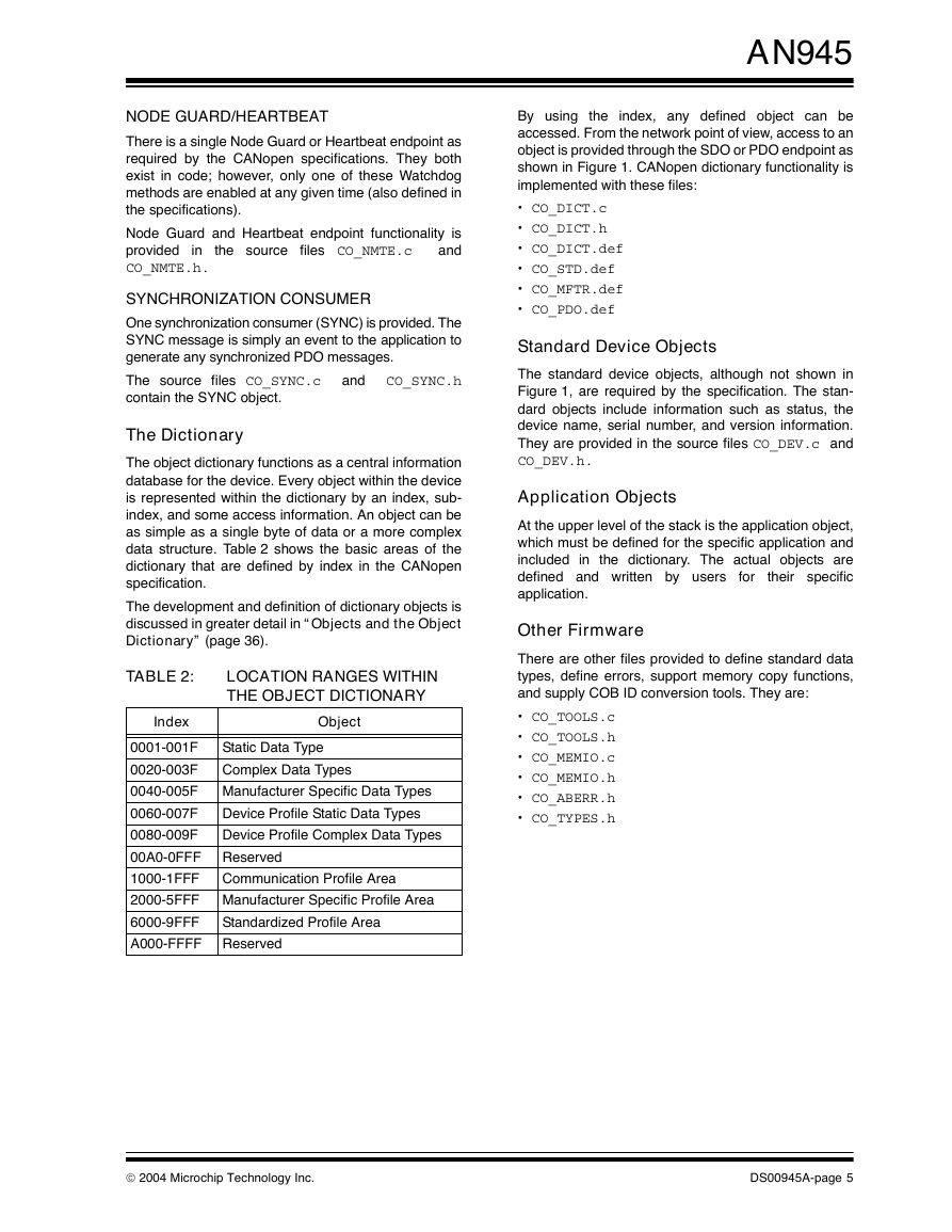
The Dictionary
The object dictionary functions as a central information
database for the device. Every object within the device
is represented within the dictionary by an index, sub-
index, and some access information. An object can be
as simple as a single byte of data or a more complex
data structure. Table 2 shows the basic areas of the
dictionary that are defined by index in the CANopen
specification.
The development and definition of dictionary objects is
discussed in greater detail in “Objects and the Object
Dictionary” (page 36).
TABLE 2:
LOCATION RANGES WITHIN
THE OBJECT DICTIONARY
Index
Object
Static Data Type
Complex Data Types
Manufacturer Specific Data Types
Device Profile Static Data Types
Device Profile Complex Data Types
Reserved
Communication Profile Area
0001-001F
0020-003F
0040-005F
0060-007F
0080-009F
00A0-0FFF
1000-1FFF
2000-5FFF Manufacturer Specific Profile Area
6000-9FFF
A000-FFFF
Standardized Profile Area
Reserved
2004 Microchip Technology Inc.
DS00945A-page 5
�
AN945
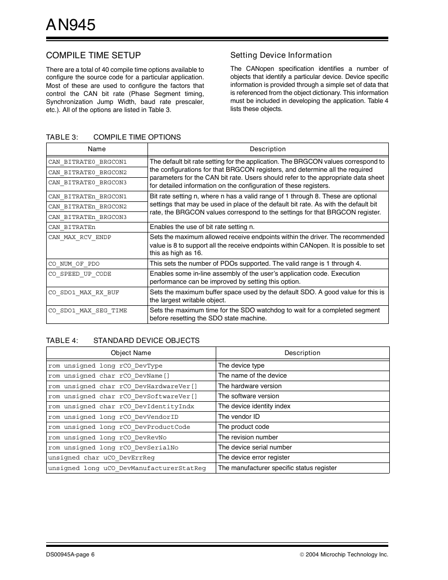
COMPILE TIME SETUP
There are a total of 40 compile time options available to
configure the source code for a particular application.
Most of these are used to configure the factors that
control the CAN bit rate (Phase Segment timing,
Synchronization Jump Width, baud rate prescaler,
etc.). All of the options are listed in Table 3.
Setting Device Information
The CANopen specification identifies a number of
objects that identify a particular device. Device specific
information is provided through a simple set of data that
is referenced from the object dictionary. This information
must be included in developing the application. Table 4
lists these objects.
TABLE 3:
COMPILE TIME OPTIONS
Name
CAN_BITRATE0_BRGCON1
CAN_BITRATE0_BRGCON2
CAN_BITRATE0_BRGCON3
CAN_BITRATEn_BRGCON1
CAN_BITRATEn_BRGCON2
CAN_BITRATEn_BRGCON3
CAN_BITRATEn
CAN_MAX_RCV_ENDP
CO_NUM_OF_PDO
CO_SPEED_UP_CODE
CO_SDO1_MAX_RX_BUF
CO_SDO1_MAX_SEG_TIME
Description
The default bit rate setting for the application. The BRGCON values correspond to
the configurations for that BRGCON registers, and determine all the required
parameters for the CAN bit rate. Users should refer to the appropriate data sheet
for detailed information on the configuration of these registers.
Bit rate setting n, where n has a valid range of 1 through 8. These are optional
settings that may be used in place of the default bit rate. As with the default bit
rate, the BRGCON values correspond to the settings for that BRGCON register.
Enables the use of bit rate setting n.
Sets the maximum allowed receive endpoints within the driver. The recommended
value is 8 to support all the receive endpoints within CANopen. It is possible to set
this as high as 16.
This sets the number of PDOs supported. The valid range is 1 through 4.
Enables some in-line assembly of the user’s application code. Execution
performance can be improved by setting this option.
Sets the maximum buffer space used by the default SDO. A good value for this is
the largest writable object.
Sets the maximum time for the SDO watchdog to wait for a completed segment
before resetting the SDO state machine.
TABLE 4:
STANDARD DEVICE OBJECTS
Object Name
Description
rom unsigned long rCO_DevType
rom unsigned char rCO_DevName[]
rom unsigned char rCO_DevHardwareVer[]
rom unsigned char rCO_DevSoftwareVer[]
rom unsigned char rCO_DevIdentityIndx
rom unsigned long rCO_DevVendorID
rom unsigned long rCO_DevProductCode
rom unsigned long rCO_DevRevNo
rom unsigned long rCO_DevSerialNo
unsigned char uCO_DevErrReg
unsigned long uCO_DevManufacturerStatReg
The device type
The name of the device
The hardware version
The software version
The device identity index
The vendor ID
The product code
The revision number
The device serial number
The device error register
The manufacturer specific status register
DS00945A-page 6
2004 Microchip Technology Inc.
�
WRITING THE APPLICATION
There is significant work that goes into developing an
application and communications according to the
CANopen specifications. The
firmware provided
eliminates some of the effort by providing some of the
lower-level communications handling. Aside from the
work necessary to develop the application itself, the
following items must be developed for the application.
Define the application objects in the dictionary
Develop handling for complex objects
Develop handling functions for the necessary
CANopen communications events
Develop PDOs
This section introduces the “toolbox” provided by the
associated firmware. All the event functions and
services are described for any application that may
need them.
AN945
Main Services
The CANopen protocol is started by calling the
mCO_InitAll() function. This issues a CAN driver
Reset and causes the boot-up message to be sent.
However, prior to starting the CANopen protocol, the
default communications specific parameters must be
set to their appropriate state. For example, the node_id
and baud rate are critical for proper messaging. Other
settings include the Node Guard settings, Heartbeat
settings, the device error object, as well as the
manufacturer specific status.
Once started, all processing occurs through the
functions
and
mCO_ProcessAllTimeEvents(). The first handles
all general communications related processing like
sending and receiving CAN messages for each
endpoint. The later function handles communication
endpoints that have specific time requirements such as
the NMTE (Heartbeat/Node Guard) and any PDO
endpoint. The mCO_ProcessAllEvents() function
should be called as often as possible to capture all
messaging
The
mCO_ProcessAllTimeEvents() function should be
called at 1 ms intervals.
mCO_ProcessAllEvents()
events
from
the
driver.
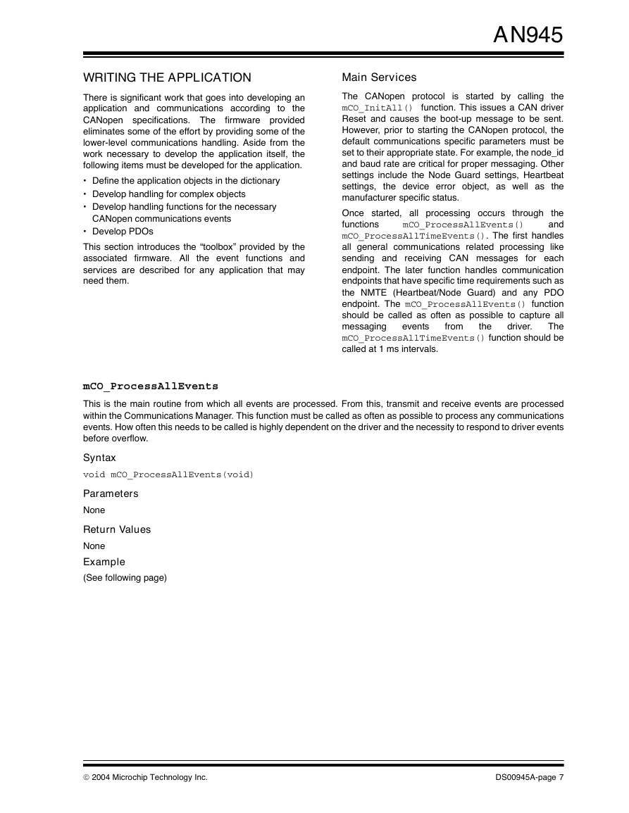
mCO_ProcessAllEvents
This is the main routine from which all events are processed. From this, transmit and receive events are processed
within the Communications Manager. This function must be called as often as possible to process any communications
events. How often this needs to be called is highly dependent on the driver and the necessity to respond to driver events
before overflow.
Syntax
void mCO_ProcessAllEvents(void)
Parameters
None
Return Values
None
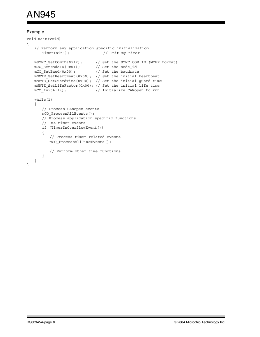
Example
(See following page)
2004 Microchip Technology Inc.
DS00945A-page 7
�
AN945
Example
void main(void)
{
// Perform any application specific initialization
TimerInit();
// Init my timer
mSYNC_SetCOBID(0x12);
mCO_SetNodeID(0x01);
mCO_SetBaud(0x00);
mNMTE_SetHeartBeat(0x00); // Set the initial heartbeat
mNMTE_SetGuardTime(0x00); // Set the initial guard time
mNMTE_SetLifeFactor(0x00); // Set the initial life time
mCO_InitAll();
// Initialize CANopen to run
// Set the SYNC COB ID (MCHP format)
// Set the node_id
// Set the baudrate
while(1)
{
// Process CANopen events
mCO_ProcessAllEvents();
// Process application specific functions
// 1ms timer events
if (TimerIsOverflowEvent())
{
// Process timer related events
mCO_ProcessAllTimeEvents();
// Perform other time functions
}
}
}
DS00945A-page 8
2004 Microchip Technology Inc.
�


 2023年江西萍乡中考道德与法治真题及答案.doc
 2012年重庆南川中考生物真题及答案.doc
 2013年江西师范大学地理学综合及文艺理论基础考研真题.doc
 2020年四川甘孜小升初语文真题及答案I卷.doc
 2020年注册岩土工程师专业基础考试真题及答案.doc
 2023-2024学年福建省厦门市九年级上学期数学月考试题及答案.doc
 2021-2022学年辽宁省沈阳市大东区九年级上学期语文期末试题及答案.doc
 2022-2023学年北京东城区初三第一学期物理期末试卷及答案.doc
 2018上半年江西教师资格初中地理学科知识与教学能力真题及答案.doc
 2012年河北国家公务员申论考试真题及答案-省级.doc
 2020-2021学年江苏省扬州市江都区邵樊片九年级上学期数学第一次质量检测试题及答案.doc
 2022下半年黑龙江教师资格证中学综合素质真题及答案.doc