logo资料库

UMAC快速参考手册.pdf

第1页 / 共109页
第2页 / 共109页
第3页 / 共109页
第4页 / 共109页
第5页 / 共109页
第6页 / 共109页
第7页 / 共109页
第8页 / 共109页
资料共109页,剩余部分请下载后查看
Motion Control Applications
UMAC Turbo System
Features
Installation and Setup
Hardware Setup
Software Setup
Programming UMAC
Online Commands
Motion Programs
PLC Programs
UMAC Tasks
Single Character I/O
Commutation Update
Servo Update
Real-Time Interrupt Tasks
Background Tasks
Configuring PEWIN
Establishing Communications
Workspace Layout
Quick Plot Feature
Saving and Retrieving PMAC Parameters
The Watch and Position Windows
Uploading and Downloading Files
Using MACRO Names and Include Files
Downloading Compiled PLCCs
The PID Tuning Utility
Auto Tuning
Interactive Tuning
Other Features
Address Configuration
Servo Cards
IO Cards
Serial Port Connections
Re-initializing UMAC
Power Supply
Motor Flag Connections
Disabling the Overtravel Limit Flags
Types of Overtravel Limits
Home Sensors
Checking the Flag Inputs
Motor Signals Connections
Incremental Encoder Connection
Checking the Encoder Inputs
MLDT Feedback Connection
DAC Output Signals
Checking the DAC Outputs
Pulse and Direction Stepper Signals
Digital Amplifier Connections
Amplifier Enable Signals
Amplifier Fault Signals
Digital Inputs and Outputs
Connection Examples
Digital Amplifier with Incremental Encoder
Analog Amplifier with Incremental Encoder
Analog Amplifier with MLDT Feedback
Stepper Driver with Incremental Encoder
Resetting UMAC
Motors Setup
Servo Loop Setup
Programming PMAC
Online Commands
Buffered (Program) Commands
Computational Features
I-Variables
P-Variables
Q-Variables
M-Variables
Arrays
Operators
Functions
Comparators
Encoder Conversion Table
Conversion Table Structure
Further Position Processing
PMAC Position Registers
Summary of Selected I-Variables
Motor Definition I-Variables
Motor Safety I-Variables
S Curve and Linear Acceleration Variables
Rate vs. Time: Programming the Maximum Acceleration Parameters
Benefits of Using S-Curve Acceleration Profiles
Motor Movement I-Variables
Servo Control I-Variables
Channel Specific I-Variables
Homing Search Moves
Jogging Moves
Indefinite Jog Commands
Jogging to a Specified Position
Jog Moves Specified by a Variable
Jog-Until-Trigger
Command and Send Statements
How PMAC Executes a Motion Program
Coordinate Systems
Axis Definitions
Axis Definition Statements
Writing a Motion Program
Running a Motion Program
Subroutines and Subprograms
Passing Arguments to Subroutines
G, M, T, and D-Codes (Machine Tool Style Programs)
NC Products
Linear Blended Moves
Linear Interpolated Moves Characteristics
Circular Interpolation
Splined Moves
PVT-Mode Moves
Turbo PMAC Lookahead Function
Turbo PMAC Kinematic Calculations
Other Programming Features
Rotary Motion Program Buffers
Internal Timebase, the Feedrate Override
External Time-Base Control (Electronic Cams)
Position Following (Electronic Gearing)
Cutter Radius Compensation
Synchronizing PMAC to other PMACs
Axis Transformation Matrices
Position-Capture and Position-Compare Functions
Learning a Motion Program
Entering a PLC Program
PLC Program Structure
Calculation Statements
Conditional Statements
Level-Triggered Conditions
Edge-Triggered Conditions
WHILE Loops
COMMAND and SEND Statements
Timers
Compiled PLC Programs
Establishing Communications
Hardware Re-initialization
The Watchdog Timer (Red LED)
System Configuration
UMAC System Status Bits
Direct Access to Hardware Features
Motor Parameters
Motion Programs
PLC Programs
I6, Error Reporting Mode
^1 Reference Guide ^2 UMAC Quick Reference ^3 Reference Guide for UMAC Products ^4 3A0-UMACQR-xPRx ^5 December 23, 2004 Single Source Machine Control Power // Flexibility // Ease of Use 21314 Lassen Street Chatsworth, CA 91311 // Tel. (818) 998-2095 Fax. (818) 998-7807 // www.deltatau.com
Copyright Information © 2003 Delta Tau Data Systems, Inc. All rights reserved. This document is furnished for the customers of Delta Tau Data Systems, Inc. Other uses are unauthorized without written permission of Delta Tau Data Systems, Inc. Information contained in this manual may be updated from time-to-time due to product improvements, etc., and may not conform in every respect to former issues. To report errors or inconsistencies, call or email: Delta Tau Data Systems, Inc. Technical Support Phone: (818) 717-5656 Fax: (818) 998-7807 Email: support@deltatau.com Website: http://www.deltatau.com Operating Conditions All Delta Tau Data Systems, Inc. motion controller products, accessories, and amplifiers contain static sensitive components that can be damaged by incorrect handling. When installing or handling Delta Tau Data Systems, Inc. products, avoid contact with highly insulated materials. Only qualified personnel should be allowed to handle this equipment. In the case of industrial applications, we expect our products to be protected from hazardous or conductive materials and/or environments that could cause harm to the controller by damaging components or causing electrical shorts. When our products are used in an industrial environment, install them into an industrial electrical cabinet or industrial PC to protect them from excessive or corrosive moisture, abnormal ambient temperatures, and conductive materials. If Delta Tau Data Systems, Inc. products are directly exposed to hazardous or conductive materials and/or environments, we cannot guarantee their operation.
UMAC Quick Reference Guide Table of Contents INTRODUCTION........................................................................................................................................................................1 Motion Control Applications .....................................................................................................................................................1 UMAC Turbo System................................................................................................................................................................2 Features..................................................................................................................................................................................3 Installation and Setup .................................................................................................................................................................5 Hardware Setup.....................................................................................................................................................................5 Software Setup .......................................................................................................................................................................5 Programming UMAC.................................................................................................................................................................6 Online Commands.................................................................................................................................................................6 Motion Programs...................................................................................................................................................................6 PLC Programs.......................................................................................................................................................................6 UMAC Tasks..............................................................................................................................................................................7 Single Character I/O .............................................................................................................................................................7 Commutation Update ............................................................................................................................................................7 Servo Update..........................................................................................................................................................................7 Real-Time Interrupt Tasks.....................................................................................................................................................8 Background Tasks..................................................................................................................................................................8 PMAC EXECUTIVE PROGRAM, PEWIN32PRO ............................................................................................................11 Configuring PEWIN.................................................................................................................................................................11 Establishing Communications ............................................................................................................................................11 Workspace Layout ...............................................................................................................................................................11 Quick Plot Feature....................................................................................................................................................................12 Saving and Retrieving PMAC Parameters..............................................................................................................................12 The Watch and Position Windows ..........................................................................................................................................13 Uploading and Downloading Files..........................................................................................................................................13 Using MACRO Names and Include Files...............................................................................................................................13 Downloading Compiled PLCCs..............................................................................................................................................13 The PID Tuning Utility ............................................................................................................................................................13 Auto Tuning..........................................................................................................................................................................14 Interactive Tuning................................................................................................................................................................15 Other Features...........................................................................................................................................................................16 HARDWARE SETUP AND CONNECTIONS.....................................................................................................................17 Address Configuration .............................................................................................................................................................17 Servo Cards..........................................................................................................................................................................17 IO Cards...............................................................................................................................................................................17 Serial Port Connections............................................................................................................................................................18 Re-initializing UMAC..........................................................................................................................................................18 Power Supply............................................................................................................................................................................19 Motor Flag Connections...........................................................................................................................................................19 Disabling the Overtravel Limit Flags.................................................................................................................................19 Types of Overtravel Limits..................................................................................................................................................19 Home Sensors ......................................................................................................................................................................20 Checking the Flag Inputs ....................................................................................................................................................20 Motor Signals Connections......................................................................................................................................................21 Incremental Encoder Connection.......................................................................................................................................21 Checking the Encoder Inputs..............................................................................................................................................21 MLDT Feedback Connection..............................................................................................................................................21 DAC Output Signals............................................................................................................................................................22 Checking the DAC Outputs.................................................................................................................................................22 Pulse and Direction Stepper Signals ..................................................................................................................................23 Digital Amplifier Connections ............................................................................................................................................23 Amplifier Enable Signals.....................................................................................................................................................24 Table of Contents i
UMAC Quick Reference Guide Amplifier Fault Signals........................................................................................................................................................24 Digital Inputs and Outputs .......................................................................................................................................................25 Connection Examples...............................................................................................................................................................26 Digital Amplifier with Incremental Encoder......................................................................................................................26 Analog Amplifier with Incremental Encoder......................................................................................................................27 Analog Amplifier with MLDT Feedback............................................................................................................................28 Stepper Driver with Incremental Encoder .........................................................................................................................29 SOFTWARE SETUP.................................................................................................................................................................31 Resetting UMAC......................................................................................................................................................................31 Motors Setup.............................................................................................................................................................................31 Servo Loop Setup .....................................................................................................................................................................31 Programming PMAC ...............................................................................................................................................................31 Online Commands...............................................................................................................................................................31 Buffered (Program) Commands .........................................................................................................................................32 Computational Features............................................................................................................................................................33 I-Variables............................................................................................................................................................................33 P-Variables ..........................................................................................................................................................................34 Q-Variables..........................................................................................................................................................................34 M-Variables .........................................................................................................................................................................35 Arrays...................................................................................................................................................................................36 Operators.............................................................................................................................................................................36 Functions..............................................................................................................................................................................37 Comparators........................................................................................................................................................................38 Encoder Conversion Table.......................................................................................................................................................38 Conversion Table Structure ................................................................................................................................................38 Further Position Processing ...............................................................................................................................................39 PMAC Position Registers ........................................................................................................................................................39 Summary of Selected I-Variables............................................................................................................................................41 Motor Definition I-Variables ..............................................................................................................................................41 Motor Safety I-Variables.....................................................................................................................................................41 S Curve and Linear Acceleration Variables.......................................................................................................................42 Rate vs. Time: Programming the Maximum Acceleration Parameters............................................................................42 Benefits of Using S-Curve Acceleration Profiles ...............................................................................................................43 Motor Movement I-Variables..............................................................................................................................................43 Servo Control I-Variables...................................................................................................................................................44 Channel Specific I-Variables ..............................................................................................................................................44 Homing Search Moves.............................................................................................................................................................45 Jogging Moves..........................................................................................................................................................................45 Indefinite Jog Commands....................................................................................................................................................45 Jogging to a Specified Position...........................................................................................................................................45 Jog Moves Specified by a Variable.....................................................................................................................................45 Jog-Until-Trigger ................................................................................................................................................................46 Command and Send Statements ..............................................................................................................................................46 MOTION PROGRAMS............................................................................................................................................................47 How PMAC Executes a Motion Program...............................................................................................................................47 Coordinate Systems..................................................................................................................................................................48 Axis Definitions....................................................................................................................................................................48 Axis Definition Statements...................................................................................................................................................49 Writing a Motion Program.......................................................................................................................................................49 Running a Motion Program .....................................................................................................................................................50 Subroutines and Subprograms .................................................................................................................................................52 Passing Arguments to Subroutines.....................................................................................................................................52 G, M, T, and D-Codes (Machine Tool Style Programs)....................................................................................................53 NC Products..............................................................................................................................................................................53 Linear Blended Moves.............................................................................................................................................................54 ii Table of Contents
UMAC Quick Reference Guide Linear Interpolated Moves Characteristics........................................................................................................................55 Circular Interpolation ...............................................................................................................................................................58 Splined Moves..........................................................................................................................................................................60 PVT-Mode Moves....................................................................................................................................................................61 Turbo PMAC Lookahead Function.........................................................................................................................................62 Turbo PMAC Kinematic Calculations....................................................................................................................................64 Other Programming Features...................................................................................................................................................65 Rotary Motion Program Buffers.........................................................................................................................................65 Internal Timebase, the Feedrate Override.........................................................................................................................65 External Time-Base Control (Electronic Cams)................................................................................................................66 Position Following (Electronic Gearing)...........................................................................................................................66 Cutter Radius Compensation..............................................................................................................................................66 Synchronizing PMAC to other PMACs..............................................................................................................................66 Axis Transformation Matrices ............................................................................................................................................67 Position-Capture and Position-Compare Functions.........................................................................................................67 Learning a Motion Program...............................................................................................................................................67 PLC PROGRAMS......................................................................................................................................................................69 Entering a PLC Program..........................................................................................................................................................70 PLC Program Structure............................................................................................................................................................71 Calculation Statements.............................................................................................................................................................71 Conditional Statements.............................................................................................................................................................71 Level-Triggered Conditions ................................................................................................................................................71 Edge-Triggered Conditions.................................................................................................................................................71 WHILE Loops ..........................................................................................................................................................................72 COMMAND and SEND Statements ......................................................................................................................................72 Timers .......................................................................................................................................................................................73 Compiled PLC Programs.........................................................................................................................................................74 TROUBLESHOOTING ............................................................................................................................................................75 Establishing Communications .................................................................................................................................................75 Hardware Re-initialization.......................................................................................................................................................75 The Watchdog Timer (Red LED)............................................................................................................................................76 System Configuration...............................................................................................................................................................76 UMAC System Status Bits.......................................................................................................................................................76 Direct Access to Hardware Features........................................................................................................................................76 Motor Parameters .....................................................................................................................................................................77 Motion Programs......................................................................................................................................................................78 PLC Programs...........................................................................................................................................................................79 APPENDIX A — UMAC ERROR CODE SUMMARY......................................................................................................81 I6, Error Reporting Mode.........................................................................................................................................................81 APPENDIX B — SELECTED UMAC I-VARIABLES SUMMARY...............................................................................83 APPENDIX C — SELECTED UMAC ONLINE COMMANDS.......................................................................................89 APPENDIX D — SELECTED UMAC MOTION PROGRAM COMMANDS..............................................................93 APPENDIX E — SELECTED UMAC PLC PROGRAM COMMANDS........................................................................95 APPENDIX F — MOTOR SUGGESTED M-VARIABLE DEFINITIONS....................................................................97 APPENDIX G — FIRST DIGITAL I/O ACCESSORY M-VARIABLES.....................................................................103 Table of Contents iii
UMAC Quick Reference Guide iv Table of Contents
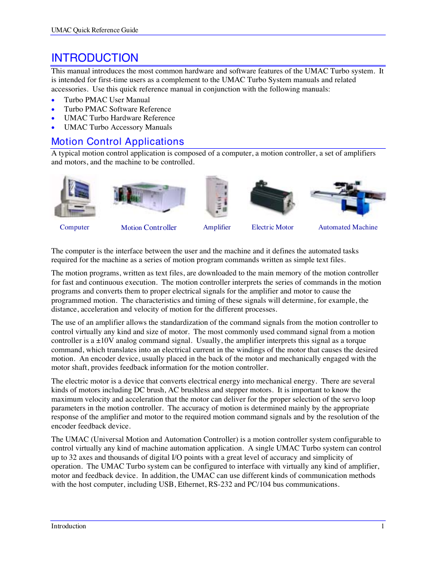
UMAC Quick Reference Guide INTRODUCTION This manual introduces the most common hardware and software features of the UMAC Turbo system. It is intended for first-time users as a complement to the UMAC Turbo System manuals and related accessories. Use this quick reference manual in conjunction with the following manuals: • Turbo PMAC User Manual • Turbo PMAC Software Reference • UMAC Turbo Hardware Reference • UMAC Turbo Accessory Manuals Motion Control Applications A typical motion control application is composed of a computer, a motion controller, a set of amplifiers and motors, and the machine to be controlled. Computer Motion Controller Amplifier Electric Motor Automated Machine The computer is the interface between the user and the machine and it defines the automated tasks required for the machine as a series of motion program commands written as simple text files. The motion programs, written as text files, are downloaded to the main memory of the motion controller for fast and continuous execution. The motion controller interprets the series of commands in the motion programs and converts them to proper electrical signals for the amplifier and motor to cause the programmed motion. The characteristics and timing of these signals will determine, for example, the distance, acceleration and velocity of motion for the different processes. The use of an amplifier allows the standardization of the command signals from the motion controller to control virtually any kind and size of motor. The most commonly used command signal from a motion controller is a ±10V analog command signal. Usually, the amplifier interprets this signal as a torque command, which translates into an electrical current in the windings of the motor that causes the desired motion. An encoder device, usually placed in the back of the motor and mechanically engaged with the motor shaft, provides feedback information for the motion controller. The electric motor is a device that converts electrical energy into mechanical energy. There are several kinds of motors including DC brush, AC brushless and stepper motors. It is important to know the maximum velocity and acceleration that the motor can deliver for the proper selection of the servo loop parameters in the motion controller. The accuracy of motion is determined mainly by the appropriate response of the amplifier and motor to the required motion command signals and by the resolution of the encoder feedback device. The UMAC (Universal Motion and Automation Controller) is a motion controller system configurable to control virtually any kind of machine automation application. A single UMAC Turbo system can control up to 32 axes and thousands of digital I/O points with a great level of accuracy and simplicity of operation. The UMAC Turbo system can be configured to interface with virtually any kind of amplifier, motor and feedback device. In addition, the UMAC can use different kinds of communication methods with the host computer, including USB, Ethernet, RS-232 and PC/104 bus communications. Introduction 1
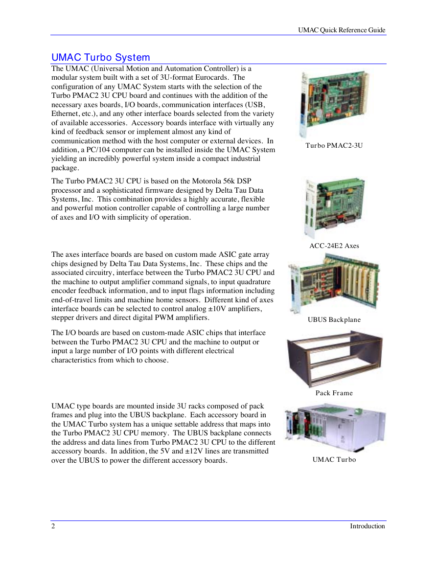
UMAC Quick Reference Guide UMAC Turbo System The UMAC (Universal Motion and Automation Controller) is a modular system built with a set of 3U-format Eurocards. The configuration of any UMAC System starts with the selection of the Turbo PMAC2 3U CPU board and continues with the addition of the necessary axes boards, I/O boards, communication interfaces (USB, Ethernet, etc.), and any other interface boards selected from the variety of available accessories. Accessory boards interface with virtually any kind of feedback sensor or implement almost any kind of communication method with the host computer or external devices. In addition, a PC/104 computer can be installed inside the UMAC System yielding an incredibly powerful system inside a compact industrial package. The Turbo PMAC2 3U CPU is based on the Motorola 56k DSP processor and a sophisticated firmware designed by Delta Tau Data Systems, Inc. This combination provides a highly accurate, flexible and powerful motion controller capable of controlling a large number of axes and I/O with simplicity of operation. The axes interface boards are based on custom made ASIC gate array chips designed by Delta Tau Data Systems, Inc. These chips and the associated circuitry, interface between the Turbo PMAC2 3U CPU and the machine to output amplifier command signals, to input quadrature encoder feedback information, and to input flags information including end-of-travel limits and machine home sensors. Different kind of axes interface boards can be selected to control analog ±10V amplifiers, stepper drivers and direct digital PWM amplifiers. The I/O boards are based on custom-made ASIC chips that interface between the Turbo PMAC2 3U CPU and the machine to output or input a large number of I/O points with different electrical characteristics from which to choose. UMAC type boards are mounted inside 3U racks composed of pack frames and plug into the UBUS backplane. Each accessory board in the UMAC Turbo system has a unique settable address that maps into the Turbo PMAC2 3U CPU memory. The UBUS backplane connects the address and data lines from Turbo PMAC2 3U CPU to the different accessory boards. In addition, the 5V and ±12V lines are transmitted over the UBUS to power the different accessory boards. Turbo PMAC2-3U ACC-24E2 Axes UBUS Backplane Pack Frame UMAC Turbo 2 Introduction
分享到:
收藏