�
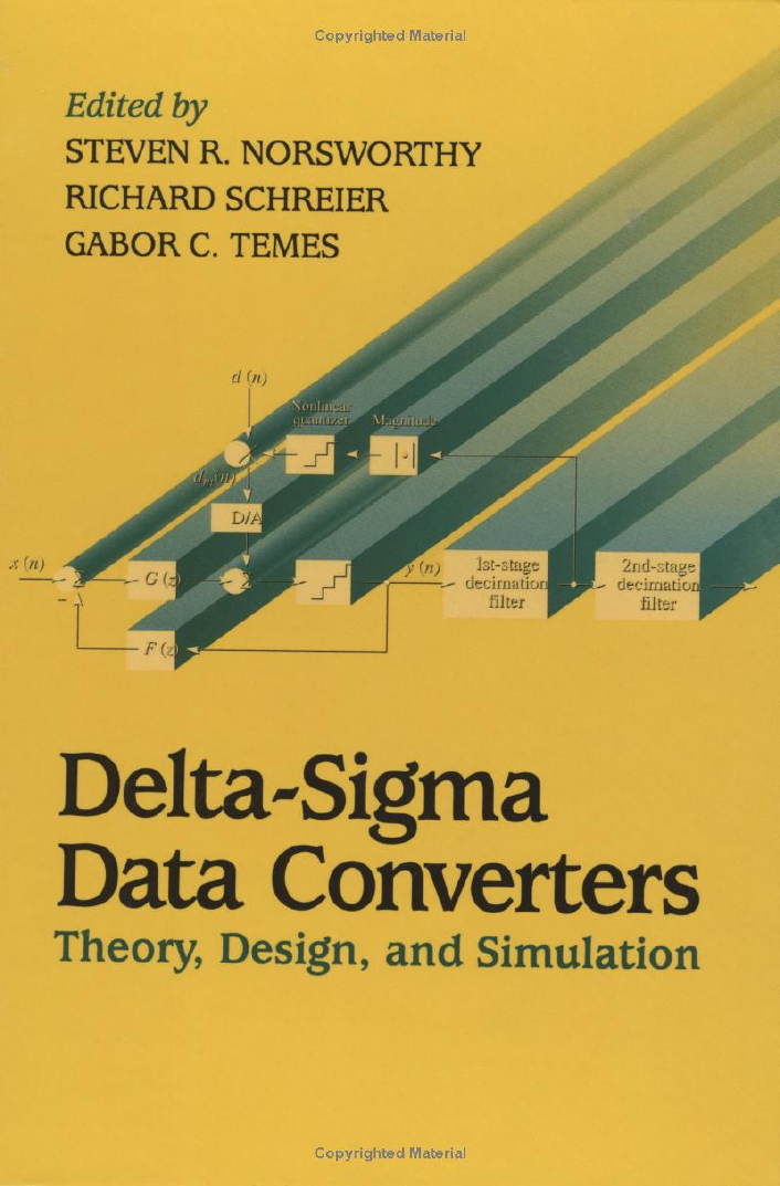
Delta-Sigma
Data Converters
IEEE Press
445 Hoes Lane, P.O. Box 1331
Piscataway, NJ 08855-1331
Editorial Board
John B. Anderson, Editor in Chief
P. M. Anderson
M. Eden
M. E. El-Hawary
S. Furui
A. H. Haddad
R. Herrick
G. F. Hoffnagle
R. F. Hoyt
S. Kartalopoulos
P. Laplante
R. S. Muller
W. D. Reeve
0.1. Wells
Dudley R. Kay, Director of Book Publishing
John Griffin, Senior Editor
Lisa Dayne, Assistant Editor
Linda Matarazzo, Editorial Assistant
Savoula Amanatidis, Production Editor
IEEE Circuits & Systems Society, Sponsor
CAS-S Liaison to IEEE Press, Jaime Ramirez-Angulo
Also of Interest from IEEE Press ...
Oversampling Delta-Sigma Data Converters: Theory, Design and Simulation
edited by James C. Candy, AT&T Bell Laboratories and Gabor C. Ternes, Oregon State University
1992
ISBN 0-87942-285-8
Hardcover
512 pp
Clock Distribution Networks in VLSI Circuits and Systems
edited by Eby G. Friedman, University of Rochester
1995
Hardcover
544 pp
ISBN 0-7803-1058-6
Nonvolatile Semiconductor Memories: Technologies, Design, and Applications
edited by Chenming Hu, University of California, Berkeley
1991
Hardcover
496 pp
ISBN 0-87942-269-6
Monolithic Phase-Locked Loops and Clock Recovery Circuits: Theory and Design
edited by Behzad Razavi, AT&T Bell Laboratories
1996
Hardcover
512 pp
ISBN 0-7803-1149-3
Routing in the Third Dimension: From VLSI Chips to MCMs
Naveed A. Sherwani, Siddharth Bhingarde, and Anand Panyam, Microprocessor Division, Intel
Corporation
1995
ISBN 0-7803-1089-6
Hardcover
376 pp
Circuits and Systems Tutorials
Chris Toumazou, Editor; Nick Battersby and Sonia Porta, Assistant Editors
1996
Softcover
700 pp
ISBN 0-7803-1170-1
�
Delta-Sigma
Data Converters
Theory, Design,
and Simulation
Edited by
Steven R. Norsworthy
Motorola
Richard Schreier
Oregon State University
Gabor C. Ternes
Oregon State University
IEEE Circuits &Systems
Society, Sponsor
+IEEE
The Institute of Electrical and Electronics Engineers, Inc., New York
mWILEY-
~ INTERSCI ENCE
A JOHN WILEY & SONS, INC., PUBLICATION
�
© 1997 THE INSTITUTE OF ELECTRICALAND ELECTRONICS
ENGINEERS, INC.
3 Park Avenue, 17th Floor, New York, NY 10016-5997
All rights reserved.
Published by John Wiley & Sons, Inc., Hoboken, New Jersey.
No part of this publication may be reproduced, stored in a retrieval system, or
transmitted in any form or by any means, electronic, mechanical,
photocopying, recording, scanning, or otherwise, except as permitted under
Section t07 or 108 of the 1976 United States Copyright Act, without either the
prior written permission of the Publisher, or authorizationthrough payment of
the appropriate per-copy fee to the Copyright Clearance Center, Inc., 222
Rosewood Drive, Danvers, MA 01923, 978-750-8400, fax 978-750-4470,or
on the web at www.copyright.com. Requests to the Publisher for permission
should be addressed to the PermissionsDepartment, John Wiley & Sons, Inc.,
III River Street, Hoboken, NJ 07030,(201) 748-6011, fax (201) 748-6008, e
mail: permcoordinator@wiley.com.
For general information on our other products and services please contact our
Customer Care Department within the U.S. at 877-762-2974, outside the U.S.
at 317-572-3993 or fax 317-572-4002.
10 9
Library of Congress Cataloging-in-Publication Data
Delta-sigma data converters: theory, design, and simulation / edited
by Steven R. Norsworthy, Richard Schreier, Gabor C. Ternes; IEEE
Circuits & Systems Society, sponsor.
p.
cm.
Includes index.
ISBN 0-7803-1045-4
1. Analog-to-digital converters.
2. Digital-to-analog converters.
1. Norsworthy, Steven R.
. III. Ternes, Gabor C.
3. Modulators (Electronics)--Design.
. II. Schreier, Richard (date)
(date)
. IV. IEEE Circuits & Systems Society.
(date)
TK7887.6.D45
621.3815'322--dc20
1996
96-14774
CIP
�
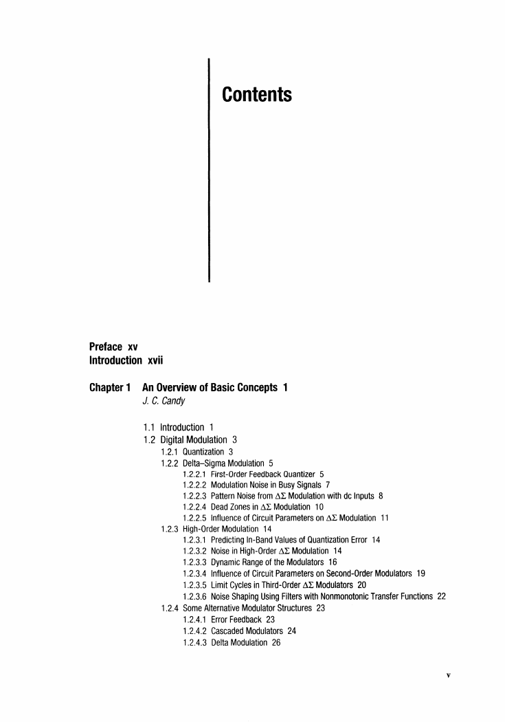
Contents
Preface
xv
Introduction
xvii
Chapter 1 An Overview of Basic Concepts
J. C. Candy
1
Introduction 1
1.1
1.2 Digital Modulation 3
1.2.1 Quantization 3
1.2.2 Delta-Sigma Modulation 5
1.2.2.1 First-Order Feedback Quantizer 5
1.2.2.2 Modulation Noise inBusy Signals
1.2.2.3 Pattern Noise from ~L Modulation with de Inputs 8
1.2.2.4 Dead Zones
1.2.2.5 Influence of Circuit Parameters
in ~L Modulation 10
on ~L Modulation 11
7
1.2.3 High-Order Modulation 14
1.2.3.1 Predicting In-Band Values of Quantization Error 14
1.2.3.2 Noise inHigh-Order ~L Modulation 14
1.2.3.3 Dynamic Range of the Modulators 16
1.2.3.4 Influence of Circuit Parameters
1.2.3.5 Limit Cycles
1.2.3.6 Noise Shaping Using Filters with Nonmonotonic Transfer Functions
inThird-Order ~L Modulators 20
on Second-Order Modulators 19
1.2.4 Some Alternative Modulator Structures
23
1.2.4.1 Error Feedback
1.2.4.2 Cascaded Modulators 24
1.2.4.3 Delta Modulation 26
23
22
v
�
vi
Contents
28
1.3 Decimating the Modulated Signal
1.3.1 Multistage Decimation 28
1.3.2 Design of the First-Stage Decimator 29
1.3.3
1.3.4
Implementing sine Decimators
The Low-Pass
Filter 35
1.4 Oversampling OfA Converters
36
32
1.4.1 Demodulating Signals at Elevated Word Rates 36
1.4.2
1.4.3 Demodulator Stage
Interpolating with sincK-Shaped
Filter Functions 37
38
1.4.3.1 Quantizing the Digital Signal 38
1.4.3.2 Quantization with Error Feedback
1.4.3.3 Cascaded Demodulators
1.4.3.4 Circuit Design for ~L Demodulation 40
38
40
1.5 Conclusion
References
41
41
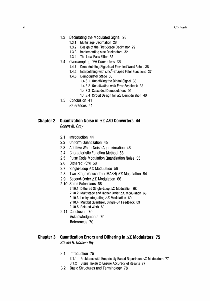
Chapter 2 Quantization Noise
Robert M. Gray
in ~L AID Converters
44
Additive White-Noise Approximation
Function Method 53
46
Pulse Code Modulation Quantization Noise 55
45
Introduction 44
2.1
2.2 Uniform Quantization
2.3
2.4 Characteristic
2.5
2.6 Dithered PCM 58
2.7
2.8 Two-Stage
2.9
2.10 Some Extensions
68
Single-Loop ~L Modulation 59
(Cascade or MASH) ~L Modulation 64
Second-Order ~L Modulation 66
2.10.1 Dithered Single-Loop ~L Modulation 68
2.10.2 Multistage and Higher Order ~L Modulation 68
2.10.3 Leaky Integrating dL Modulation 69
2.10.4 Multibit Quantizer, Single-Bit Feedback
2.10.5 Related Work 69
69
2.11 Conclusion 70
Acknowledgments
References
70
70
Chapter 3 Quantization
Errors
Steven R. Norsworthy
and Dithering
in ~L Modulators
75
3.1
3.2
Introduction 75
3.1.1
3.1.2
Basic Structures
Problems with Empirically Based Reports on dL Modulators 77
Steps Taken to Ensure Accuracy of Results
77
and Terminology
78
�
Contents
vii
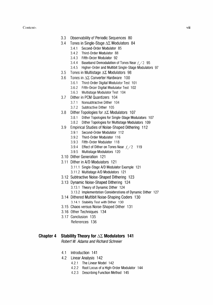
3.3 Observability of Periodic Sequences
3.4
80
inSingle-Stage ~L Modulators 84
Second-Order Modulator 85
Third-Order Modulator 88
Fifth-Order Modulator 92
Baseband Demodulation of Tones Near j~,/2 95
Tones
3.4.1
3.4.2
3.4.3
3.4.4
3.4.5 Higher-Order and Multibit Single-Stage Modulators 97
Tones
Tones
3.6.1
3.6.2
3.6.3 Multistage Modulator Test 104
in Multistage ~L Modulators 98
in ~L Converter Hardware
100
Third-Order Digital Modulator Test
101
Fifth-Order Digital Modulator Test 102
3.5
3.6
3.7 Dither in PCM Quantizers
104
Nonsubtractive Dither 104
Subtractive Dither 105
3.7.1
3.7.2
3.8 Dither Topologies
for ~L Modulators
107
3.9
107
109
for Single-Stage Modulators
for Multistage Modulators
3.8.1
Dither Topologies
3.8.2 Dither Topologies
Empirical Studies of Noise-Shaped Dithering 112
3.9.1
3.9.2
3.9.3
3.9.4
3.9.5 Multistage Modulators
Second-Order Modulator 112
Third-Order Modulator 116
Fifth-Order Modulator 118
Effect of Dither on Tones Near /,./2
119
120
3.10 Dither Generation
121
3.11 Dither inAID Modulators
121
Single-Stage
3.11.1
3.11.2 Multistage AID Modulators
AID Modulator Example
121
121
3.12 Subtractive Noise-Shaped Dithering 123
3.13 Dynamic Noise-Shaped Dithering 124
3.13.1 Theory of Dynamic Dither 124
3.13.2 Implementation Considerations
of Dynamic Dither 127
3.14 Dithered Multibit Noise-Shaping Coders
130
3.14.1 Stability Test with Dither 130
3.15 Chaos versus Noise-Shaped Dither 131
3.16 Other Techniques
3.17 Conclusion
135
136
References
134
Chapter 4
Stability Theory for ~L Modulators
Robert W Adams and Richard Schreier
141
4.1
4.2
142
Introduction 141
Linear Analysis
4.2.1
4.2.2
4.2.3 Describing Function Method 145
The Linear Model 142
Root Locus ofa High-Order Modulator 144
�



 2023年江西萍乡中考道德与法治真题及答案.doc
 2012年重庆南川中考生物真题及答案.doc
 2013年江西师范大学地理学综合及文艺理论基础考研真题.doc
 2020年四川甘孜小升初语文真题及答案I卷.doc
 2020年注册岩土工程师专业基础考试真题及答案.doc
 2023-2024学年福建省厦门市九年级上学期数学月考试题及答案.doc
 2021-2022学年辽宁省沈阳市大东区九年级上学期语文期末试题及答案.doc
 2022-2023学年北京东城区初三第一学期物理期末试卷及答案.doc
 2018上半年江西教师资格初中地理学科知识与教学能力真题及答案.doc
 2012年河北国家公务员申论考试真题及答案-省级.doc
 2020-2021学年江苏省扬州市江都区邵樊片九年级上学期数学第一次质量检测试题及答案.doc
 2022下半年黑龙江教师资格证中学综合素质真题及答案.doc