PACKML UNIT/MACHINE
IMPLEMENTATION GUIDE
Part 1: PackML Interface State Manager
Summary
This document “PackML Interface State Manager is the first part of the PackML unit/machine
Implementation Guide. The PackML unit/machine Implementation Guide is a Best Practice
Recommendation based on ANSI/ISA TR88.00.02-2015. The purpose of this guideline is to
help companies with different knowledge levels to implement PackML interfaces on
Units/Machines. This document contains best practice recommendations based on the real
implementation of PackML interfaces by a number of OMAC member companies as well as
other users.
This document is the first part in a series of document related to build PackML unit/machines.
Further documents are forthcoming and will focus on issues such as PackML Machine
software code structure, PackML network connections, PackML and Safety, PackML and Line
Integration and PackML HMI.
Author: Ph.D. Carsten Nøkleby, SESAM-World
Ver. 1.00
Page 0 of 97
�
1. Contents
2. Executive Summary ........................................................................................................................... 4
2.1
2.2
2.3
2.4
Purpose ................................................................................................................................... 4
Goals ....................................................................................................................................... 4
Background ............................................................................................................................. 4
Related PackML documents in process ................................................................................ 5
3. Scope of the Implementation Guide .................................................................................................. 6
3.1
PackML Interface State Manager ......................................................................................... 8
4. Terminologies, Definitions and Abbreviations ................................................................................. 9
4.1
4.2
4.3
ISA 88.01 ................................................................................................................................ 9
The ISA 88 Physical Model .................................................................................................... 9
ISA 88 Recipe Management – unit/machine control recipe parameters .......................... 10
5. Identifying and defining a Unit ...................................................................................................... 13
6. The PackML Interface State Model ................................................................................................ 15
6.1
6.2
6.3
6.4
6.5
The syntax of the PackML state model .............................................................................. 15
The PackML Interface State Model .................................................................................... 15
Colours used for the PackML State Model ......................................................................... 17
The PackML State Model from a unit/machine perspective ............................................. 17
The PackML State Model from an internal and external perspective ............................. 19
The PackML State Model from a unit/machine parameter perspective – production
6.6
orders 20
7. PackML Event State Manager ........................................................................................................ 23
7.1
7.2
7.3
7.4
7.5
7.6
7.7
7.8
7.9
Resetting ............................................................................................................................... 24
Starting ................................................................................................................................. 26
Execute ................................................................................................................................. 28
Holding.................................................................................................................................. 30
Unholding ............................................................................................................................. 35
Suspending ........................................................................................................................... 39
Unsuspending ....................................................................................................................... 42
Completing ........................................................................................................................... 45
Stopping ................................................................................................................................ 47
7.10 Aborting ................................................................................................................................ 49
7.11 Mapping table ....................................................................................................................... 52
7.12 Mapping Alarms to event triggers to PackML ................................................................... 54
8. PackML Control Command definitions .......................................................................................... 55
8.1
PackML Commands ............................................................................................................. 55
Ver. 1.00
Page 1 of 97
�
8.2
Specification of commands on unit HMI and from External system ................................ 59
9. PackML Interface State definition ................................................................................................. 59
10. Unit control modes ......................................................................................................................... 64
11. PackTags......................................................................................................................................... 66
11.1 Description and definition of PackTags .............................................................................. 68
12. Example of Unit Controller Functionality ................................................................................... 69
12.1 Syntax and Symbolic description ........................................................................................ 69
12.2 Prepare unit/machine .......................................................................................................... 70
12.3 Start unit/machine ............................................................................................................... 71
12.4 Stop unit/machine from Unit panel/HMI ........................................................................... 73
12.5 Stop unit/machine from external system ........................................................................... 74
12.6 Operator Break and pause on unit/machine ...................................................................... 76
12.7 Resume unit/machine after break from External System ................................................. 77
12.8 Stop Unit from unit panel/HMI........................................................................................... 78
12.9 Abort unit/machine .............................................................................................................. 80
12.10 Re-start unit from unit panel/HMI after stop or abort ...................................................... 81
12.11 Re-start unit from External system after stop or abort .................................................... 82
12.12 Alarm and warning on unit ................................................................................................. 83
12.12.1 PackML alarm and event state management table ................................................... 84
12.13 Background task: OEE ........................................................................................................ 86
12.14 Background task: Mode & State ......................................................................................... 87
12.15 Suspend: Starvation or saturation ...................................................................................... 89
12.16 Unsuspend ............................................................................................................................ 90
13. Reference information ................................................................................................................... 91
13.1 Definitions and abbreviations ............................................................................................. 91
13.2 References ............................................................................................................................. 92
13.3 List of people involved in preparation of the guideline ..................................................... 93
13.4 Support ................................................................................................................................. 95
13.5 The author ............................................................................................................................ 95
14. Version History .............................................................................................................................. 96
Ver. 1.00
Page 2 of 97
�
This page is initially left blank.
Ver. 1.00
Page 3 of 97
�
2. EXECUTIVE SUMMARY
2.1
PURPOSE
This PackML Interface State Manager document is the first part of the PackML unit/machine
Implementation Guide, which is a Best Practice Recommendation based on ANSI/ISA
TR88.00.02-2015. This guideline will help companies, with varying levels of knowledge and
experience, to gain familiarity with the ANSI/ISA TR88.00.02-2015 technical report, and how to
apply the procedures described to real-world machine applications. The PackML Interface State
Manager is focused on the execution of a Production Order on a machine, and not how the
machine performing its control functions. A unit/machine is defined as a collection of physical
equipment and control functions that perform one or more major processing functions. A
unit/machine can be a single machine or a subset of a whole packaging line.
The background information for this document has been collected from four workgroup meetings
held in 2015 and 2016. The practical experience from the members of the workgroup has been
used to construct ready-to-use, generic and vendor-independent implementation models.
This PackML implementation guide is intended for Machine Suppliers, system integrators and
End Users. This guideline describes the requirements for a unit/machine to be compliant with the
PackML standard as described in ANSI/ISA TR88.00.02-2015, and provides examples of
implementations that can be used as guidance for specific machines.
GOALS
2.2
This PackML implementation guide provides a definition of the minimum requirements of a
PackML interface. For example, there are practical examples on how different conditions can be
handled when an error or event occurs on the equipment level that generates an alarm or
warning. It also addresses how different interpretation from different users may be reconciled.
The guideline provides examples of how to configure the PackML State model transitions
according to specific End User requirements.
Furthermore, the guideline takes the maturity level of Machine Suppliers into consideration, as
well as Machine Suppliers readiness or ability to implement PackML partly or fully.
Benefits for both End Users and Machine Suppliers include:
Easy integration of unit/machines and test of interfaces
Reduction of integration cost for a complete packaging line.
Same operator Interface from a supervisory system
Faster interface specification
Less risk / Less uncertainty in commercial contract
Less training effort
Reliable data, e.g. OEE, energy data
Replace one unit/machine at a line
Etc.
BACKGROUND
2.3
The OMAC End Users want to achieve a unified way of interfacing with units/machines on the
factory floor. Providing this unified interface will ensure easy integration with a supervisory
control system. There are similar interfaces to all units, and the units have the same data
structure interfaces available.
Ver. 1.00
Page 4 of 97
�
By applying a unified user interface based on the PackML State Model an operator can be guided
in case of an unplanned stoppage. Furthermore, there can be common event handling on all units,
providing the End User the possibility to view stop reasons in a common way for all units.
The interface described in this document is built on the international reference model PackML
defined by The International Society of Automation (ISA). The interface follows the PackML State
Model as described in the reference ANSI/ISA TR88.00.02-2015.
Basic understanding and knowledge of the TR88.00.02 technical report is required before reading
this Best Practice Recommendation. In fact, it is strongly recommended to have the report in
hand when reading this document.
A unit/machine is defined as a collection of physical equipment and control functions that perform
one or more major processing functions. A unit/machine can be a single machine or a subset of a
whole packaging line. The term unit and machine are used interchangeably in this document.
Machine Suppliers are defined as companies or organizations that provide PackML compliant
unit/machines. End users are defined as companies or organizations that use PackML compliant
unit/machines in production facilities.
RELATED PACKML DOCUMENTS IN PROCESS
2.4
This document is the first part in a series of documents related to build PackML unit/machines.
Further documents1 will come and have focus on issues like:
• Part 1: PackML Interface State Manager
• Part 2: PackML Machine Software Code Structure
• Part 3: PackML Network Connections
• Part 4: PackML and Safety
• Part 5: PackML and Line Integration
• Part 6: PackML User Interface - HMI
1 The list is not complete and there could be changes in the document titles.
Ver. 1.00
Page 5 of 97
�
3. SCOPE OF THE IMPLEMENTATION GUIDE
The PackML unit/machine Implementation Guide Part 1 focuses only on an individual
unit/machine and its PackML Interface implementation, without any relationship to other
units/machines or equipment.
The document does not cover how several Units/Machines are operated together in a line.
The PackML specification is an implementation of the ANSI/ISA-TR88.00.02-2015, Machine and
unit/machine States. As an implementation example of ANSI/ISA-88.00.01, it covers the
following two application examples:
1. PackML Interface State Manager2
2. PackML Machine State Manager (Not part of this document3)
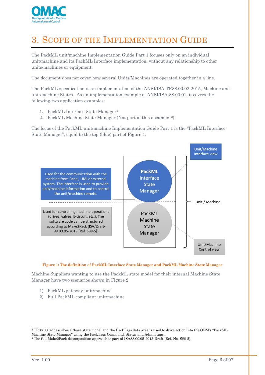
The focus of the PackML unit/machine Implementation Guide Part 1 is the “PackML Interface
State Manager”, equal to the top (blue) part of Figure 1.
Figure 1: The definition of PackML Interface State Manager and PackML Machine State Manager
Machine Suppliers wanting to use the PackML state model for their internal Machine State
Manager have two scenarios shown in Figure 2:
1) PackML gateway unit/machine
2) Full PackML compliant unit/machine
2 TR88.00.02 describes a “base state model and the PackTags data area is used to drive action into the OEM’s “PackML
Machine State Manager“ using the PackTags Command, Status and Admin tags.
3 The full Make2Pack decomposition approach is part of ISA88.00.05-2013-Draft [Ref. No. S88-5].
Ver. 1.00
Page 6 of 97
�
The focus of the PackML unit/machine Implementation Guide Part 1 is the PackML Gateway
solution and covers the PackML Interface State Manager.
Figure 2: Mapping 4 of PackML Interface State Manger and Integrated Machine State Manager & PackML
Interface
To implement a PackML gateway, Machine Suppliers must map the PackML Interface state
model to their specific internal state logic3.
Machine Suppliers that use a PackML gateway unit/machine, must specify the mapping between
the PackML Interface State Manager and their specific Machine State Manager. Normally, all
Machine Suppliers should be able to fulfil the mapping to the PackML Interface State Manager.
When Machine Suppliers have a Machine State Manager based on PackML it is not necessary to
specify any mapping between the PackML Interface State Manager and the Machine State
Manager because they are the same5.
The PackML gateway approach makes sense for legacy equipment, and for Machine Suppliers
that have fixed requirements for internal machine state logic.
To obtain a full PackML unit/machine it is often required that the unit/machine must be
reprogrammed in accordance with ISA-88 [Ref. S88-1], PackML [Ref TR88] and Make2Pack [Ref.
S88-5-Draft].
4 The mapping table is in section 7.11.
5 In the case where a machine has multiple state managers, only one state manager should be presented to external
systems, with appropriate mapping defined.
Ver. 1.00
Page 7 of 97
�


 2023年江西萍乡中考道德与法治真题及答案.doc
 2012年重庆南川中考生物真题及答案.doc
 2013年江西师范大学地理学综合及文艺理论基础考研真题.doc
 2020年四川甘孜小升初语文真题及答案I卷.doc
 2020年注册岩土工程师专业基础考试真题及答案.doc
 2023-2024学年福建省厦门市九年级上学期数学月考试题及答案.doc
 2021-2022学年辽宁省沈阳市大东区九年级上学期语文期末试题及答案.doc
 2022-2023学年北京东城区初三第一学期物理期末试卷及答案.doc
 2018上半年江西教师资格初中地理学科知识与教学能力真题及答案.doc
 2012年河北国家公务员申论考试真题及答案-省级.doc
 2020-2021学年江苏省扬州市江都区邵樊片九年级上学期数学第一次质量检测试题及答案.doc
 2022下半年黑龙江教师资格证中学综合素质真题及答案.doc