PUBLISHED
SFF-8472 Rev 12.3
SFF specifications are available at http://www.snia.org/sff/specifications
SFF-8472
Specification for
Management Interface for SFP+
Rev 12.3 July 29, 2018
Secretariat: SFF TA TWG
Abstract: This specification defines an enhanced digital diagnostic monitoring interface for optical
transceivers which allows real time access to device operating parameters.
This specification is made available for public review, and written comments are solicited from readers.
Comments received at http://www.snia.org/feedback will be considered for inclusion in future revisions of this
specification.
POINTS OF CONTACT:
Chairman SFF TA TWG
Email: SFF-Chair@snia.org
David Lewis
Lumentum
400 N. McCarthy Blvd.
Milpitas, CA 95035
Ph: 408-546-5448
Email: david.lewis@lumentum.com
Management Interface for SFP+
Page 1
Copyright © 2018 SNIA. All rights reserved
�
PUBLISHED
Intellectual Property
SFF-8472 Rev 12.3
The user's attention is called to the possibility that implementation of this specification may require the use of
an invention covered by patent rights. By distribution of this specification, no position is taken with respect to
the validity of a claim or claims or of any patent rights in connection therewith.
This specification is considered SNIA Architecture and is covered by the SNIA IP Policy and as a result goes
through a request for disclosure when it is published. Additional information can be found at the following
locations:
• Results of IP Disclosures: http://www.snia.org/sffdisclosures
• SNIA IP Policy: http://www.snia.org/ippolicy
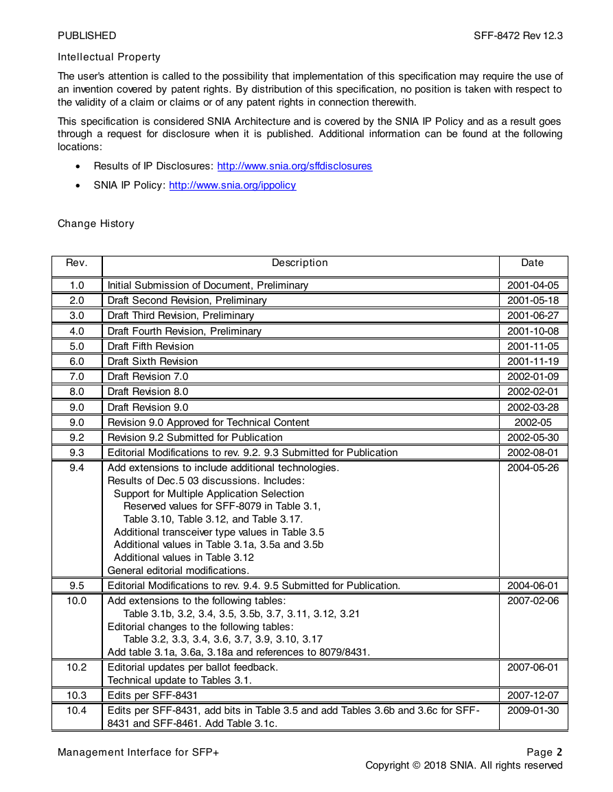
Change History
Rev.
Description
1.0
2.0
3.0
4.0
5.0
6.0
7.0
8.0
9.0
9.0
9.2
9.3
9.4
9.5
10.0
10.2
10.3
10.4
Initial Submission of Document, Preliminary
Draft Second Revision, Preliminary
Draft Third Revision, Preliminary
Draft Fourth Revision, Preliminary
Draft Fifth Revision
Draft Sixth Revision
Draft Revision 7.0
Draft Revision 8.0
Draft Revision 9.0
Revision 9.0 Approved for Technical Content
Revision 9.2 Submitted for Publication
Editorial Modifications to rev. 9.2. 9.3 Submitted for Publication
Add extensions to include additional technologies.
Results of Dec.5 03 discussions. Includes:
Support for Multiple Application Selection
Reserved values for SFF-8079 in Table 3.1,
Table 3.10, Table 3.12, and Table 3.17.
Additional transceiver type values in Table 3.5
Additional values in Table 3.1a, 3.5a and 3.5b
Additional values in Table 3.12
General editorial modifications.
Editorial Modifications to rev. 9.4. 9.5 Submitted for Publication.
Add extensions to the following tables:
Table 3.1b, 3.2, 3.4, 3.5, 3.5b, 3.7, 3.11, 3.12, 3.21
Editorial changes to the following tables:
Table 3.2, 3.3, 3.4, 3.6, 3.7, 3.9, 3.10, 3.17
Add table 3.1a, 3.6a, 3.18a and references to 8079/8431.
Editorial updates per ballot feedback.
Technical update to Tables 3.1.
Edits per SFF-8431
Edits per SFF-8431, add bits in Table 3.5 and add Tables 3.6b and 3.6c for SFF-
8431 and SFF-8461. Add Table 3.1c.
Date
2001-04-05
2001-05-18
2001-06-27
2001-10-08
2001-11-05
2001-11-19
2002-01-09
2002-02-01
2002-03-28
2002-05
2002-05-30
2002-08-01
2004-05-26
2004-06-01
2007-02-06
2007-06-01
2007-12-07
2009-01-30
Management Interface for SFP+
Page 2
Copyright © 2018 SNIA. All rights reserved
�
PUBLISHED
SFF-8472 Rev 12.3
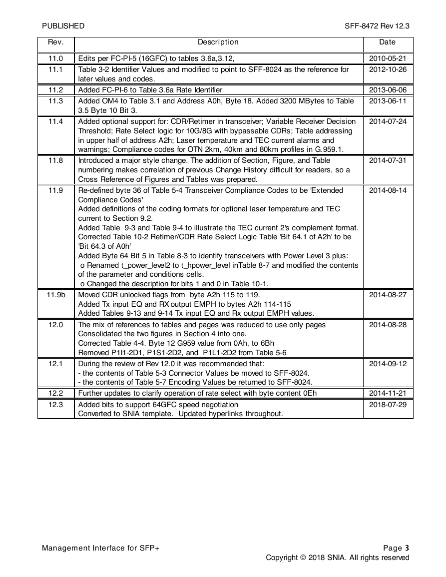
Rev.
11.0
11.1
11.2
11.3
11.4
11.8
11.9
Description
Edits per FC-PI-5 (16GFC) to tables 3.6a,3.12,
Table 3-2 Identifier Values and modified to point to SFF-8024 as the reference for
later values and codes.
Added FC-PI-6 to Table 3.6a Rate Identifier
Added OM4 to Table 3.1 and Address A0h, Byte 18. Added 3200 MBytes to Table
3.5 Byte 10 Bit 3.
Added optional support for: CDR/Retimer in transceiver; Variable Receiver Decision
Threshold; Rate Select logic for 10G/8G with bypassable CDRs; Table addressing
in upper half of address A2h; Laser temperature and TEC current alarms and
warnings; Compliance codes for OTN 2km, 40km and 80km profiles in G.959.1.
Introduced a major style change. The addition of Section, Figure, and Table
numbering makes correlation of previous Change History difficult for readers, so a
Cross Reference of Figures and Tables was prepared.
Re-defined byte 36 of Table 5-4 Transceiver Compliance Codes to be 'Extended
Compliance Codes'
Added definitions of the coding formats for optional laser temperature and TEC
current to Section 9.2.
Added Table 9-3 and Table 9-4 to illustrate the TEC current 2's complement format.
Corrected Table 10-2 Retimer/CDR Rate Select Logic Table 'Bit 64.1 of A2h' to be
'Bit 64.3 of A0h'
Added Byte 64 Bit 5 in Table 8-3 to identify transceivers with Power Level 3 plus:
o Renamed t_power_level2 to t_hpower_level inTable 8-7 and modified the contents
of the parameter and conditions cells.
o Changed the description for bits 1 and 0 in Table 10-1.
Date
2010-05-21
2012-10-26
2013-06-06
2013-06-11
2014-07-24
2014-07-31
2014-08-14
11.9b Moved CDR unlocked flags from byte A2h 115 to 119.
2014-08-27
Added Tx input EQ and RX output EMPH to bytes A2h 114-115
Added Tables 9-13 and 9-14 Tx input EQ and Rx output EMPH values.
The mix of references to tables and pages was reduced to use only pages
Consolidated the two figures in Section 4 into one.
Corrected Table 4-4. Byte 12 G959 value from 0Ah, to 6Bh
Removed P1I1-2D1, P1S1-2D2, and P1L1-2D2 from Table 5-6
During the review of Rev 12.0 it was recommended that:
- the contents of Table 5-3 Connector Values be moved to SFF-8024.
- the contents of Table 5-7 Encoding Values be returned to SFF-8024.
Further updates to clarify operation of rate select with byte content 0Eh
Added bits to support 64GFC speed negotiation
Converted to SNIA template. Updated hyperlinks throughout.
12.0
12.1
12.2
12.3
2014-08-28
2014-09-12
2014-11-21
2018-07-29
Management Interface for SFP+
Page 3
Copyright © 2018 SNIA. All rights reserved
�
PUBLISHED
Foreword
SFF-8472 Rev 12.3
The development work on this specification was done by the SNIA SFF TWG, an industry group. Since its
formation as the SFF Committee in August 1990, the membership has included a mix of companies which
are leaders across the industry.
When 2 1/2" diameter disk drives were introduced, there was no commonality on external dimensions e.g.
physical size, mounting locations, connector type, connector location, between vendors. The SFF Committee
provided a forum for system integrators and vendors to define the form factor of disk drives.
During their definition, other activities were suggested because participants in SFF faced more challenges
than the form factors. In November 1992, the charter was expanded to address any issues of general int erest
and concern to the storage industry. The SFF Committee became a forum for resolving industry issues that
are either not addressed by the standards process or need an immediate solution.
In July 2016, the SFF Committee transitioned to SNIA (Storage Networking Industry Association), as a TA
(Technology Affiliate) TWG (Technical Work Group).
Industry consensus is not a requirement to publish a specification because it is recognized that in an
emerging product area, there is room for more than one approach. By making the documentation on
competing proposals available, an integrator can examine the alternatives available and select the product
that is felt to be most suitable.
SFF meets during the T10 (see http://www.incits.org/committees/t10) and T11 (see
http://www.incits.org/committees/t11) weeks, and SSWGs (Specific Subject Working Groups) are held at the
convenience of the participants.
Many of the specifications developed by SFF have either been incorporated into standards or adopted as
standards by ANSI, EIA, JEDEC and SAE.
For those who wish to participate in the activities of the SFF TWG, the signup for membership can b e found
at:
http://www.snia.org/sff/join
The complete list of SFF Specifications which have been completed or are currently being worked on by the
SFF TA TWG can be found at:
http://www.snia.org/sff/specifications
Suggestions for improvement of this specification will be welcome, they should be submitted to:
http://www.snia.org/feedback
Management Interface for SFP+
Page 4
Copyright © 2018 SNIA. All rights reserved
�
PUBLISHED
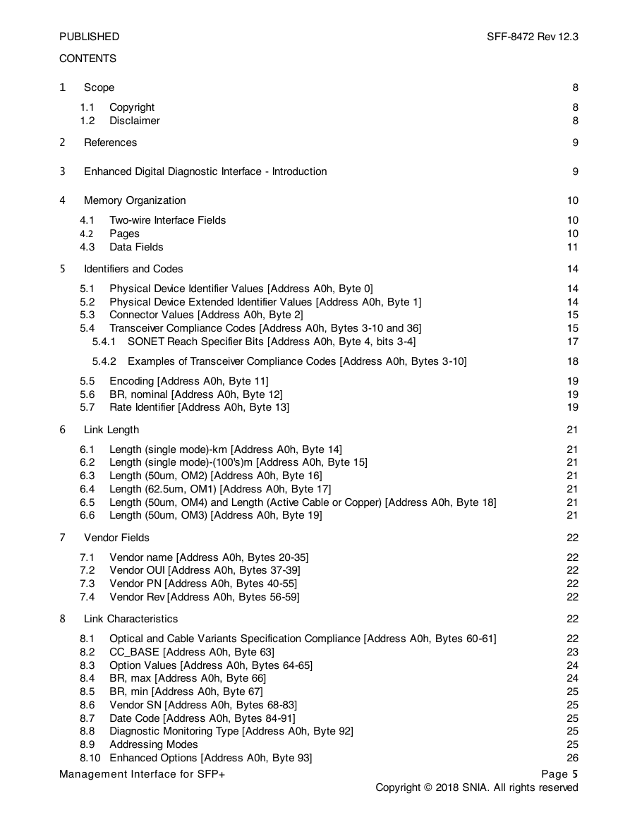
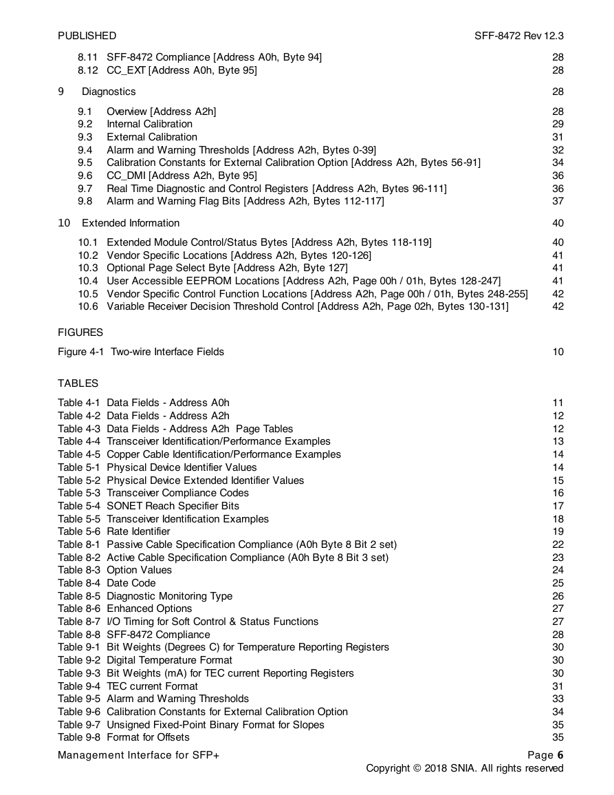
CONTENTS
1
Scope
1.1 Copyright
1.2 Disclaimer
References
Enhanced Digital Diagnostic Interface - Introduction
2
3
4 Memory Organization
4.1 Two-wire Interface Fields
4.2 Pages
4.3 Data Fields
5
Identifiers and Codes
5.1 Physical Device Identifier Values [Address A0h, Byte 0]
5.2 Physical Device Extended Identifier Values [Address A0h, Byte 1]
5.3 Connector Values [Address A0h, Byte 2]
5.4 Transceiver Compliance Codes [Address A0h, Bytes 3-10 and 36]
5.4.1 SONET Reach Specifier Bits [Address A0h, Byte 4, bits 3-4]
5.4.2 Examples of Transceiver Compliance Codes [Address A0h, Bytes 3-10]
5.5 Encoding [Address A0h, Byte 11]
5.6 BR, nominal [Address A0h, Byte 12]
5.7 Rate Identifier [Address A0h, Byte 13]
6
Link Length
6.1
6.2
6.3
6.4
6.5
6.6
Length (single mode)-km [Address A0h, Byte 14]
Length (single mode)-(100's)m [Address A0h, Byte 15]
Length (50um, OM2) [Address A0h, Byte 16]
Length (62.5um, OM1) [Address A0h, Byte 17]
Length (50um, OM4) and Length (Active Cable or Copper) [Address A0h, Byte 18]
Length (50um, OM3) [Address A0h, Byte 19]
7
Vendor Fields
7.1 Vendor name [Address A0h, Bytes 20-35]
7.2 Vendor OUI [Address A0h, Bytes 37-39]
7.3 Vendor PN [Address A0h, Bytes 40-55]
7.4 Vendor Rev [Address A0h, Bytes 56-59]
8
Link Characteristics
SFF-8472 Rev 12.3
8
8
8
9
9
10
10
10
11
14
14
14
15
15
17
18
19
19
19
21
21
21
21
21
21
21
22
22
22
22
22
22
8.1 Optical and Cable Variants Specification Compliance [Address A0h, Bytes 60-61]
8.2 CC_BASE [Address A0h, Byte 63]
8.3 Option Values [Address A0h, Bytes 64-65]
8.4 BR, max [Address A0h, Byte 66]
8.5 BR, min [Address A0h, Byte 67]
8.6 Vendor SN [Address A0h, Bytes 68-83]
8.7 Date Code [Address A0h, Bytes 84-91]
8.8 Diagnostic Monitoring Type [Address A0h, Byte 92]
8.9 Addressing Modes
8.10 Enhanced Options [Address A0h, Byte 93]
22
23
24
24
25
25
25
25
25
26
Page 5
Copyright © 2018 SNIA. All rights reserved
Management Interface for SFP+
�
PUBLISHED
SFF-8472 Rev 12.3
8.11 SFF-8472 Compliance [Address A0h, Byte 94]
8.12 CC_EXT [Address A0h, Byte 95]
9
Diagnostics
9.1 Overview [Address A2h]
9.2
Internal Calibration
9.3 External Calibration
9.4 Alarm and Warning Thresholds [Address A2h, Bytes 0-39]
9.5 Calibration Constants for External Calibration Option [Address A2h, Bytes 56-91]
9.6 CC_DMI [Address A2h, Byte 95]
9.7 Real Time Diagnostic and Control Registers [Address A2h, Bytes 96-111]
9.8 Alarm and Warning Flag Bits [Address A2h, Bytes 112-117]
10 Extended Information
10.1 Extended Module Control/Status Bytes [Address A2h, Bytes 118-119]
10.2 Vendor Specific Locations [Address A2h, Bytes 120-126]
10.3 Optional Page Select Byte [Address A2h, Byte 127]
10.4 User Accessible EEPROM Locations [Address A2h, Page 00h / 01h, Bytes 128-247]
10.5 Vendor Specific Control Function Locations [Address A2h, Page 00h / 01h, Bytes 248-255]
10.6 Variable Receiver Decision Threshold Control [Address A2h, Page 02h, Bytes 130-131]
FIGURES
Figure 4-1 Two-wire Interface Fields
TABLES
Table 4-1 Data Fields - Address A0h
Table 4-2 Data Fields - Address A2h
Table 4-3 Data Fields - Address A2h Page Tables
Table 4-4 Transceiver Identification/Performance Examples
Table 4-5 Copper Cable Identification/Performance Examples
Table 5-1 Physical Device Identifier Values
Table 5-2 Physical Device Extended Identifier Values
Table 5-3 Transceiver Compliance Codes
Table 5-4 SONET Reach Specifier Bits
Table 5-5 Transceiver Identification Examples
Table 5-6 Rate Identifier
Table 8-1 Passive Cable Specification Compliance (A0h Byte 8 Bit 2 set)
Table 8-2 Active Cable Specification Compliance (A0h Byte 8 Bit 3 set)
Table 8-3 Option Values
Table 8-4 Date Code
Table 8-5 Diagnostic Monitoring Type
Table 8-6 Enhanced Options
Table 8-7 I/O Timing for Soft Control & Status Functions
Table 8-8 SFF-8472 Compliance
Table 9-1 Bit Weights (Degrees C) for Temperature Reporting Registers
Table 9-2 Digital Temperature Format
Table 9-3 Bit Weights (mA) for TEC current Reporting Registers
Table 9-4 TEC current Format
Table 9-5 Alarm and Warning Thresholds
Table 9-6 Calibration Constants for External Calibration Option
Table 9-7 Unsigned Fixed-Point Binary Format for Slopes
Table 9-8 Format for Offsets
28
28
28
28
29
31
32
34
36
36
37
40
40
41
41
41
42
42
10
11
12
12
13
14
14
15
16
17
18
19
22
23
24
25
26
27
27
28
30
30
30
31
33
34
35
35
Management Interface for SFP+
Page 6
Copyright © 2018 SNIA. All rights reserved
�
PUBLISHED
SFF-8472 Rev 12.3
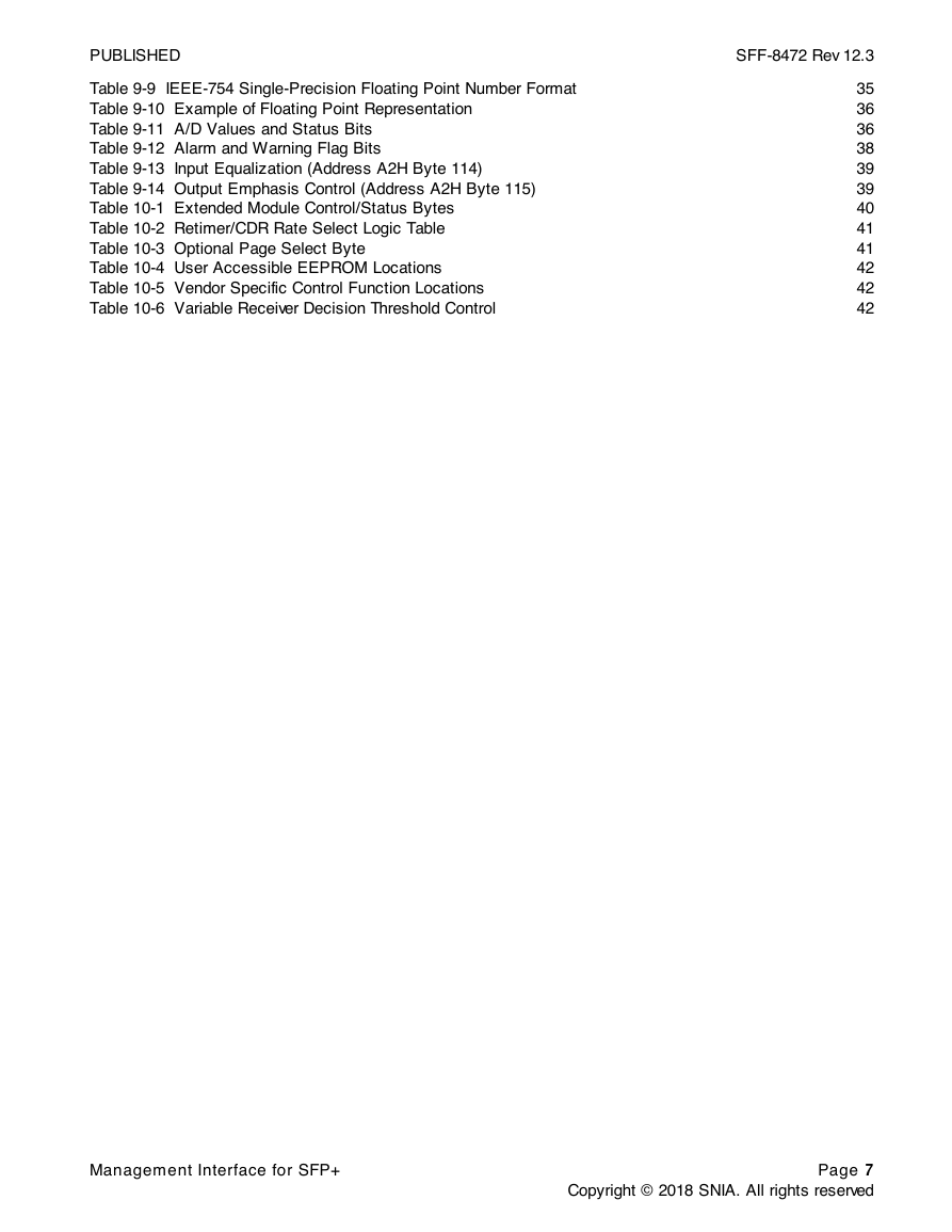
Table 9-9 IEEE-754 Single-Precision Floating Point Number Format
Table 9-10 Example of Floating Point Representation
Table 9-11 A/D Values and Status Bits
Table 9-12 Alarm and Warning Flag Bits
Table 9-13 Input Equalization (Address A2H Byte 114)
Table 9-14 Output Emphasis Control (Address A2H Byte 115)
Table 10-1 Extended Module Control/Status Bytes
Table 10-2 Retimer/CDR Rate Select Logic Table
Table 10-3 Optional Page Select Byte
Table 10-4 User Accessible EEPROM Locations
Table 10-5 Vendor Specific Control Function Locations
Table 10-6 Variable Receiver Decision Threshold Control
35
36
36
38
39
39
40
41
41
42
42
42
Management Interface for SFP+
Page 7
Copyright © 2018 SNIA. All rights reserved
�
PUBLISHED
1
Scope
SFF-8472 Rev 12.3
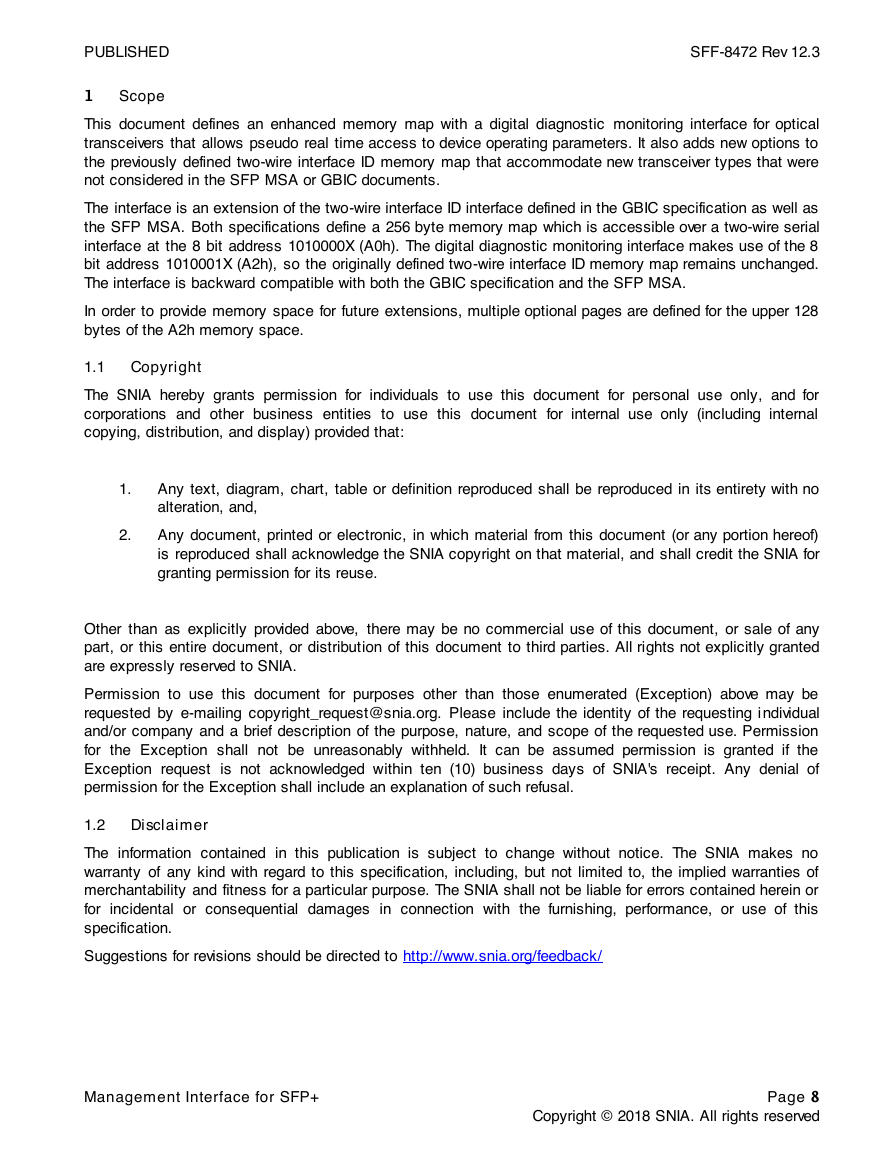
This document defines an enhanced memory map with a digital diagnostic monitoring interface for optical
transceivers that allows pseudo real time access to device operating parameters. It also adds new options to
the previously defined two-wire interface ID memory map that accommodate new transceiver types that were
not considered in the SFP MSA or GBIC documents.
The interface is an extension of the two-wire interface ID interface defined in the GBIC specification as well as
the SFP MSA. Both specifications define a 256 byte memory map which is accessible over a two-wire serial
interface at the 8 bit address 1010000X (A0h). The digital diagnostic monitoring interface makes use of the 8
bit address 1010001X (A2h), so the originally defined two-wire interface ID memory map remains unchanged.
The interface is backward compatible with both the GBIC specification and the SFP MSA.
In order to provide memory space for future extensions, multiple optional pages are defined for the upper 128
bytes of the A2h memory space.
1.1 Copyright
The SNIA hereby grants permission for individuals to use this document for personal use only, and for
corporations and other business entities to use this document for internal use only (including internal
copying, distribution, and display) provided that:
1.
2.
Any text, diagram, chart, table or definition reproduced shall be reproduced in its entirety with no
alteration, and,
Any document, printed or electronic, in which material from this document (or any portion hereof)
is reproduced shall acknowledge the SNIA copyright on that material, and shall credit the SNIA for
granting permission for its reuse.
Other than as explicitly provided above, there may be no commercial use of this document, or sale of any
part, or this entire document, or distribution of this document to third parties. All rights not explicitly granted
are expressly reserved to SNIA.
Permission to use this document for purposes other than those enumerated (Exception) above may be
requested by e-mailing copyright_request@snia.org. Please include the identity of the requesting i ndividual
and/or company and a brief description of the purpose, nature, and scope of the requested use. Permission
for the Exception shall not be unreasonably withheld. It can be assumed permission is granted if the
Exception request is not acknowledged within ten (10) business days of SNIA's receipt. Any denial of
permission for the Exception shall include an explanation of such refusal.
1.2 Disclaimer
The information contained in this publication is subject to change without notice. The SNIA makes no
warranty of any kind with regard to this specification, including, but not limited to, the implied warranties of
merchantability and fitness for a particular purpose. The SNIA shall not be liable for errors contained herein or
for incidental or consequential damages in connection with the furnishing, performance, or use of this
specification.
Suggestions for revisions should be directed to http://www.snia.org/feedback/
Management Interface for SFP+
Page 8
Copyright © 2018 SNIA. All rights reserved
�



 2023年江西萍乡中考道德与法治真题及答案.doc
 2012年重庆南川中考生物真题及答案.doc
 2013年江西师范大学地理学综合及文艺理论基础考研真题.doc
 2020年四川甘孜小升初语文真题及答案I卷.doc
 2020年注册岩土工程师专业基础考试真题及答案.doc
 2023-2024学年福建省厦门市九年级上学期数学月考试题及答案.doc
 2021-2022学年辽宁省沈阳市大东区九年级上学期语文期末试题及答案.doc
 2022-2023学年北京东城区初三第一学期物理期末试卷及答案.doc
 2018上半年江西教师资格初中地理学科知识与教学能力真题及答案.doc
 2012年河北国家公务员申论考试真题及答案-省级.doc
 2020-2021学年江苏省扬州市江都区邵樊片九年级上学期数学第一次质量检测试题及答案.doc
 2022下半年黑龙江教师资格证中学综合素质真题及答案.doc