FANUC Series 30*/300*/300*s-MODEL A
FANUC Series 31*/310*/310*s-MODEL A5
FANUC Series 31*/310*/310*s-MODEL A
FANUC Series 32*/320*/320*s-MODEL A
PMC
PROGRAMMING MANUAL
B-63983EN/02
�
� ��������������
����
����������������������
��
�������
� ����������
�
���
�
���
�����
�
������������������ �
����
� ����
��
���
� �������������
����������
�������������� ����� ��
���
�
����� �������
��
������ �����
���
������ ����� ����������
�����������
�
��
����
������� ������
��������� ��������
������������
�������� �����
������������
������� ������
��������
�������� �����������
� ������
��������
� �����
� ���
�����
��
� ���������� �������������
������
�
�
�
���
� ������� ����������
� �����
��������
����������
�����������
����
��
����
����� �������
������������!
�����
���!�
�
����
������
��
��� ����������
�����������
���
���������� ��������
�� ��������
�
� � ���� ���
������� ��������"�� ��� �������
��� ��
����� ������� � � ����
����� ����
��
�������������������
�� ����
������
�
B-63983EN/02 DEFINITION OF WARNING, CAUTION, AND NOTE
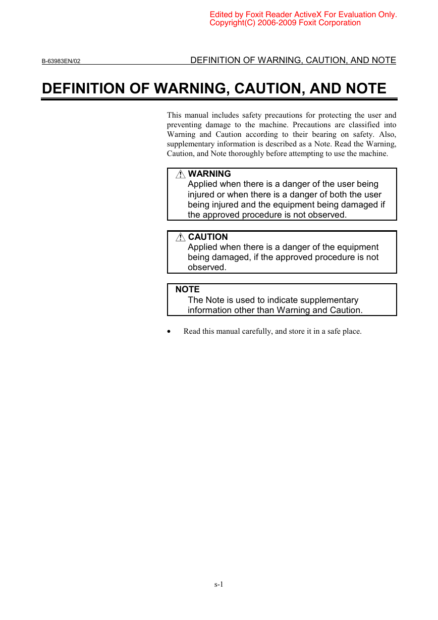
DEFINITION OF WARNING, CAUTION, AND NOTE
This manual includes safety precautions for protecting the user and
preventing damage to the machine. Precautions are classified into
Warning and Caution according to their bearing on safety. Also,
supplementary information is described as a Note. Read the Warning,
Caution, and Note thoroughly before attempting to use the machine.
WARNING
Applied when there is a danger of the user being
injured or when there is a danger of both the user
being injured and the equipment being damaged if
the approved procedure is not observed.
CAUTION
Applied when there is a danger of the equipment
being damaged, if the approved procedure is not
observed.
NOTE
The Note is used to indicate supplementary
information other than Warning and Caution.
•
Read this manual carefully, and store it in a safe place.
s-1
�
�
B-63983EN/02 TABLE OF CONTENTS
TABLE OF CONTENTS
1.2
1.1
Volume 1 of 2
DEFINITION OF WARNING, CAUTION, AND NOTE.................................s-1
1 OVERVIEW OF PMC .............................................................................1
WHAT IS PMC? ............................................................................................ 2
Basic Configuration of PMC....................................................................................2
1.1.1
1.1.2
I/O Signals of PMC..................................................................................................2
1.1.3
PMC Signal Addresses.............................................................................................3
WHAT IS LADDER LANGUAGE? ................................................................. 6
1.2.1
Ladder Diagram Format ...........................................................................................6
Signal Name (Symbol Name)...................................................................................7
1.2.2
Comment ..................................................................................................................7
1.2.3
1.2.4
Graphic Symbols of Relays and Coils......................................................................8
Line Number and Net Number.................................................................................8
1.2.5
1.2.6
Difference Between Relay Sequence Circuit and Ladder Sequence Program.........9
1.2.7
SPECIFICATION OF EXTENDED SYMBOL AND COMMENT......................10
SEQUENCE PROGRAM CREATION PROCEDURE.................................. 13
1.3.1
Determining Specification .....................................................................................13
Creating Ladder Diagram.......................................................................................13
1.3.2
Editing Sequence Program.....................................................................................14
1.3.3
1.3.4
Transferring and Writing Sequence Program to PMC...........................................15
Checking Sequence Program..................................................................................16
1.3.5
1.3.6
Storage and Management of Sequence Program....................................................16
EXECUTION OF SEQUENCE PROGRAM ................................................. 17
Execution Procedure of Sequence Program...........................................................18
1.4.1
1.4.2
Repetitive Operation ..............................................................................................19
Processing Priority (1st Level, 2nd Level, and 3rd Level) ....................................20
1.4.3
Structured Sequence Program................................................................................22
1.4.4
Implementation .................................................................................................. 22
1.4.4.1
1.4.4.2
Subprogramming and nesting............................................................................. 28
1.4.4.3
Notes on using subroutines ................................................................................ 32
Synchronization Processing of I/O Signals............................................................34
1.4.5
Interlock .................................................................................................................39
1.4.6
1.4.7
Notes on I/O Signals Updated by Other Than PMC ..............................................40
MULTI-PMC FUNCTION ............................................................................. 41
1.3
1.4
1.5
c-1
�
TABLE OF CONTENTS B-63983EN/02
2
2.2
1.5.1
1.5.2
1.5.3
1.5.4
Execution Order and Execution Time Percentage .................................................43
Setting I/O Address for I/O Link............................................................................45
Interface Between CNC and PMC .........................................................................46
Multi-Path PMC Interface......................................................................................48
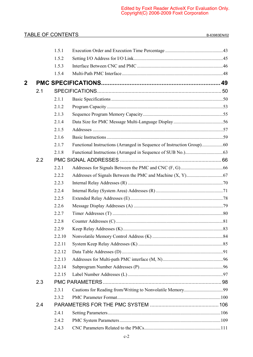
PMC SPECIFICATIONS.......................................................................49
SPECIFICATIONS....................................................................................... 50
2.1
2.1.1
Basic Specifications ...............................................................................................50
Program Capacity...................................................................................................53
2.1.2
2.1.3
Sequence Program Memory Capacity....................................................................55
Data Size for PMC Message Multi-Language Display..........................................56
2.1.4
Addresses ...............................................................................................................57
2.1.5
2.1.6
Basic Instructions ...................................................................................................59
Functional Instructions (Arranged in Sequence of Instruction Group)..................60
2.1.7
2.1.8
Functional Instructions (Arranged in Sequence of SUB No.)................................63
PMC SIGNAL ADDRESSES ....................................................................... 66
Addresses for Signals Between the PMC and CNC (F, G)....................................66
2.2.1
Addresses of Signals Between the PMC and Machine (X, Y)...............................67
2.2.2
2.2.3
Internal Relay Addresses (R) .................................................................................70
Internal Relay (System Area) Addresses (R) .........................................................71
2.2.4
Extended Relay Addresses (E)...............................................................................78
2.2.5
2.2.6
Message Display Addresses (A) ............................................................................79
Timer Addresses (T) ..............................................................................................80
2.2.7
2.2.8
Counter Addresses (C) ...........................................................................................81
2.2.9
Keep Relay Addresses (K).....................................................................................83
2.2.10 Nonvolatile Memory Control Address (K) ............................................................84
2.2.11
System Keep Relay Addresses (K) ........................................................................85
2.2.12 Data Table Addresses (D) ......................................................................................91
2.2.13 Addresses for Multi-path PMC interface (M, N)...................................................96
2.2.14
Subprogram Number Addresses (P).......................................................................96
2.2.15
Label Number Addresses (L) .................................................................................97
PMC PARAMETERS................................................................................... 98
2.3.1
Cautions for Reading from/Writing to Nonvolatile Memory.................................99
2.3.2
PMC Parameter Format........................................................................................100
PARAMETERS FOR THE PMC SYSTEM ................................................ 106
Setting Parameters................................................................................................106
2.4.1
PMC System Parameters......................................................................................109
2.4.2
2.4.3
CNC Parameters Related to the PMCs.................................................................111
2.3
2.4
c-2
�
B-63983EN/02 TABLE OF CONTENTS
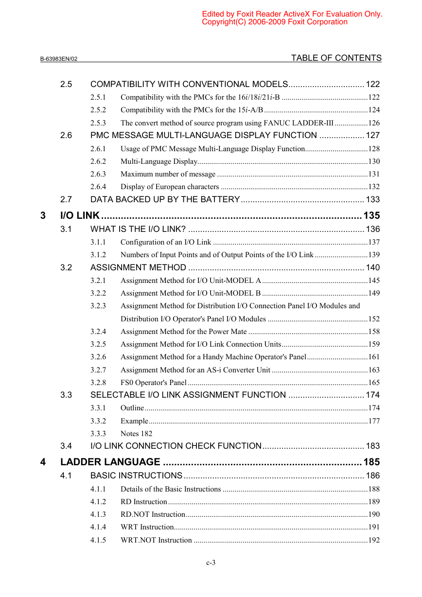
2.5
2.6
3.2
COMPATIBILITY WITH CONVENTIONAL MODELS................................ 122
Compatibility with the PMCs for the 16i/18i/21i-B ............................................122
2.5.1
Compatibility with the PMCs for the 15i-A/B.....................................................124
2.5.2
2.5.3
The convert method of source program using FANUC LADDER-III.................126
PMC MESSAGE MULTI-LANGUAGE DISPLAY FUNCTION ................... 127
Usage of PMC Message Multi-Language Display Function................................128
2.6.1
2.6.2
Multi-Language Display.......................................................................................130
Maximum number of message .............................................................................131
2.6.3
2.6.4
Display of European characters ...........................................................................132
2.7
DATA BACKED UP BY THE BATTERY.................................................... 133
I/O LINK.............................................................................................135
3.1
WHAT IS THE I/O LINK? .......................................................................... 136
Configuration of an I/O Link ...............................................................................137
3.1.1
3.1.2
Numbers of Input Points and of Output Points of the I/O Link ...........................139
ASSIGNMENT METHOD .......................................................................... 140
Assignment Method for I/O Unit-MODEL A......................................................145
3.2.1
Assignment Method for I/O Unit-MODEL B ......................................................149
3.2.2
3.2.3
Assignment Method for Distribution I/O Connection Panel I/O Modules and
Distribution I/O Operator's Panel I/O Modules ...................................................152
Assignment Method for the Power Mate .............................................................158
3.2.4
Assignment Method for I/O Link Connection Units............................................159
3.2.5
Assignment Method for a Handy Machine Operator's Panel...............................161
3.2.6
Assignment Method for an AS-i Converter Unit .................................................163
3.2.7
3.2.8
FS0 Operator's Panel ............................................................................................165
SELECTABLE I/O LINK ASSIGNMENT FUNCTION ................................ 174
3.3.1
Outline..................................................................................................................174
Example................................................................................................................177
3.3.2
3.3.3
Notes 182
3.4
I/O LINK CONNECTION CHECK FUNCTION........................................... 183
LADDER LANGUAGE .......................................................................185
4.1
BASIC INSTRUCTIONS............................................................................ 186
Details of the Basic Instructions ..........................................................................188
4.1.1
RD Instruction......................................................................................................189
4.1.2
4.1.3
RD.NOT Instruction.............................................................................................190
4.1.4 WRT Instruction...................................................................................................191
4.1.5 WRT.NOT Instruction .........................................................................................192
3.3
c-3
3
4
�
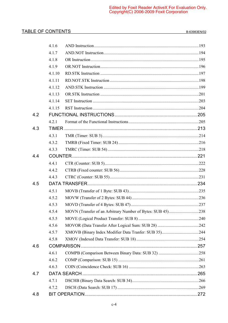
TABLE OF CONTENTS B-63983EN/02
AND Instruction...................................................................................................193
4.1.6
AND.NOT Instruction..........................................................................................194
4.1.7
OR Instruction......................................................................................................195
4.1.8
OR.NOT Instruction.............................................................................................196
4.1.9
RD.STK Instruction .............................................................................................197
4.1.10
4.1.11
RD.NOT.STK Instruction ....................................................................................198
4.1.12 AND.STK Instruction ..........................................................................................199
4.1.13 OR.STK Instruction .............................................................................................201
4.1.14
SET Instruction ....................................................................................................203
4.1.15
RST Instruction ....................................................................................................204
FUNCTIONAL INSTRUCTIONS................................................................ 205
4.2.1
Format of the Functional Instructions..................................................................205
TIMER ....................................................................................................... 213
TMR (Timer: SUB 3)...........................................................................................214
4.3.1
4.3.2
TMRB (Fixed Timer: SUB 24) ............................................................................216
4.3.3
TMRC (Timer: SUB 54) ......................................................................................218
COUNTER................................................................................................. 221
4.4.1
CTR (Counter: SUB 5).........................................................................................222
CTRB (Fixed counter: SUB 56)...........................................................................228
4.4.2
4.4.3
CTRC (Counter: SUB 55)....................................................................................231
DATA TRANSFER..................................................................................... 234
MOVB (Transfer of 1 Byte: SUB 43)..................................................................235
4.5.1
MOVW (Transfer of 2 Bytes: SUB 44) ...............................................................236
4.5.2
4.5.3
MOVD (Transfer of 4 Bytes: SUB 47)................................................................237
MOVN (Transfer of an Arbitrary Number of Bytes: SUB 45)............................238
4.5.4
4.5.5
MOVE (Logical Product Transfer: SUB 8) .........................................................240
MOVOR (Data Transfer After Logical Sum: SUB 28) .......................................242
4.5.6
XMOVB (Binary Index Modifier Data Tranfer: SUB 35)...................................244
4.5.7
4.5.8
XMOV (Indexed Data Transfer: SUB 18)...........................................................254
COMPARISON .......................................................................................... 257
COMPB (Comparison Between Binary Data: SUB 32) ......................................258
4.6.1
4.6.2
COMP (Comparison: SUB 15) ............................................................................261
4.6.3
COIN (Coincidence Check: SUB 16) ..................................................................263
DATA SEARCH ......................................................................................... 265
4.7.1
DSCHB (Binary Data Search: SUB 34)...............................................................266
4.7.2
DSCH (Data Search: SUB 17) .............................................................................269
BIT OPERATION....................................................................................... 272
c-4
4.2
4.3
4.4
4.5
4.6
4.7
4.8
�




 2023年江西萍乡中考道德与法治真题及答案.doc
 2012年重庆南川中考生物真题及答案.doc
 2013年江西师范大学地理学综合及文艺理论基础考研真题.doc
 2020年四川甘孜小升初语文真题及答案I卷.doc
 2020年注册岩土工程师专业基础考试真题及答案.doc
 2023-2024学年福建省厦门市九年级上学期数学月考试题及答案.doc
 2021-2022学年辽宁省沈阳市大东区九年级上学期语文期末试题及答案.doc
 2022-2023学年北京东城区初三第一学期物理期末试卷及答案.doc
 2018上半年江西教师资格初中地理学科知识与教学能力真题及答案.doc
 2012年河北国家公务员申论考试真题及答案-省级.doc
 2020-2021学年江苏省扬州市江都区邵樊片九年级上学期数学第一次质量检测试题及答案.doc
 2022下半年黑龙江教师资格证中学综合素质真题及答案.doc