Journal of Modern Physics, 2017, 8, 2209-2218
http://www.scirp.org/journal/jmp
ISSN Online: 2153-120X
ISSN Print: 2153-1196
Electromagnetic Interpretation of
Fractional-Order Elements
Guishu Liang, Jiawei Hao*, Dongqing Shan
Department of Electric Engineering, North China Electric Power University, Baoding, China
How to cite this paper: Liang, G.S., Hao,
J.W. and Shan, D.Q. (2017) Electromagnetic
Interpretation of Fractional-Order Elements.
Journal of Modern Physics, 8, 2209-2218.
https://doi.org/10.4236/jmp.2017.814136
Received: November 8, 2017
Accepted: December 18, 2017
Published: December 21, 2017
Copyright © 2017 by authors and
Scientific Research Publishing Inc.
This work is licensed under the Creative
Commons Attribution International
License (CC BY 4.0).
http://creativecommons.org/licenses/by/4.0/
Open Access
Abstract
Fractional circuits have attracted extensive attention of scholars and research-
ers for their superior performance and potential applications. Recently, the
fundamentals of the conventional circuit theory were extended to include the
new generalized elements and fractional-order elements. As is known to all,
circuit theory is a limiting special case of electromagnetic field theory and the
characterization of classical circuit elements can be given an elegant electro-
magnetic interpretation. In this paper, considering fractional-order time de-
rivatives, an electromagnetic field interpretation of fractional-order elements:
fractional-order inductor, fractional-order capacitor and fractional-order mu-
tual inductor is presented, in terms of a quasi-static expansion of the fraction-
al Maxwell’s equations. It shows that fractional-order elements can also be in-
terpreted as a fractional electromagnetic system. As the element order equals
to 1, the interpretation of fractional-order elements matches that of the clas-
sical circuit elements: L, C, and mutual inductor, respectively.
Keywords
Fractional Circuits, Fractional-Order Elements, Maxwell’s Equations,
Electromagnetic Field
1. Introduction
Recently, the realization and generalization of fractional calculus has become of
great significance in many fields [1] such as determining voltage-current rela-
tionship in a non-ideal capacitor, fractal behavior of a metal insulator solution
interface, electromagnetic waves, and recently in electrical circuits such as filters
[2]-[7], oscillators [8] [9] [10], passive realization [11] [12] and energy-related
issues in supercapacitors [13]. Furthermore, applications of fractional calculus
have been reported in many areas such as physics [14], nonlinear oscillation of
earthquakes [15], and mathematical biology [16].
DOI: 10.4236/jmp.2017.814136 Dec. 21, 2017
2209
Journal of Modern Physics
�
G. S. Liang et al.
DOI: 10.4236/jmp.2017.814136
Fractional calculus has higher capability of providing accurate description
than integer dynamical systems. In the circuit theory, the fractional-order ele-
ment with impedance proportional to sα is considered as a generalized ele-
ment that covers the conventional circuit elements when the order of elements
equals to integer [17]. And the fractional-order mutual inductance is the genera-
lized concept of the mutual inductance in the fractional-order domain [18]. Due
to the extra fractional-order parameters, more flexibility is added. During the
last 10 years, several promising trials have been introduced for the realizations of
the fractional-order element and based on different techniques such as chemical
reactions [19], fractal shapes [20], and graphene material [21]. Moreover, many
finite circuit approximations were suggested to model fractional-order elements
[22] [23] [24] [25].
In the framework of fractional calculus, there are lots of literatures about
Maxwell’s equations. Tarasov [26] formulated the fractional Green’s, Stokes’ and
Gauss’s theorems and realized the proofs of these theorems for simple regions.
He considered fractional nonlocal Maxwell’s equations and the corresponding
fractional wave equations. Tarasov [27] used the fractional integrals to describe
fractal distribution. Tarasov [28] suggested a fractional generalization of the
integral Maxwell equations. Lazo [29] proposed a spatially symmetric and causal
gauge invariant fractional electromagnetic field from a Lagrangian formulation.
Electromagnetic field propagation has also been modeled using the fractional
calculus [30].
It is well known that circuit theory is a limiting special case of electromagnetic
field theory. In particular, the characterization of the four classical circuit ele-
ments can be given an elegant electromagnetic interpretation by the quasi-static
expansion of Max-well’s equations [31] [32] [33]. The electromagnetic interpre-
tation of classical circuit elements in Laplace domain is introduced in [34]. The
fractional-order elements appeared, but there was no electromagnetic field in-
terpretation of fractional-order elements yet. So, by considering fractional-order
time derivatives, this paper is to give an analogous interpretation for the charac-
terization of fractional-order elements.
This paper is organized as follows: in Section 2, the notions of fractional cal-
culus and fractional-order elements and fractional Maxwell’s equations are pre-
sented. After that, the quasi-static expansion of fractional Maxwell’s equations
and the electromagnetic field interpretation of fractional-order elements are
shown in Section 3. Finally, conclusions are found in Section 4. In this section,
some preliminary definitions are presented.
2. Preliminaries
This section is devoted to introducing some preliminaries, which help us to state
the results of the paper.
2.1. Fractional Calculus
The first definition is about fractional derivative operator as a generalization for
2210
Journal of Modern Physics
�
G. S. Liang et al.
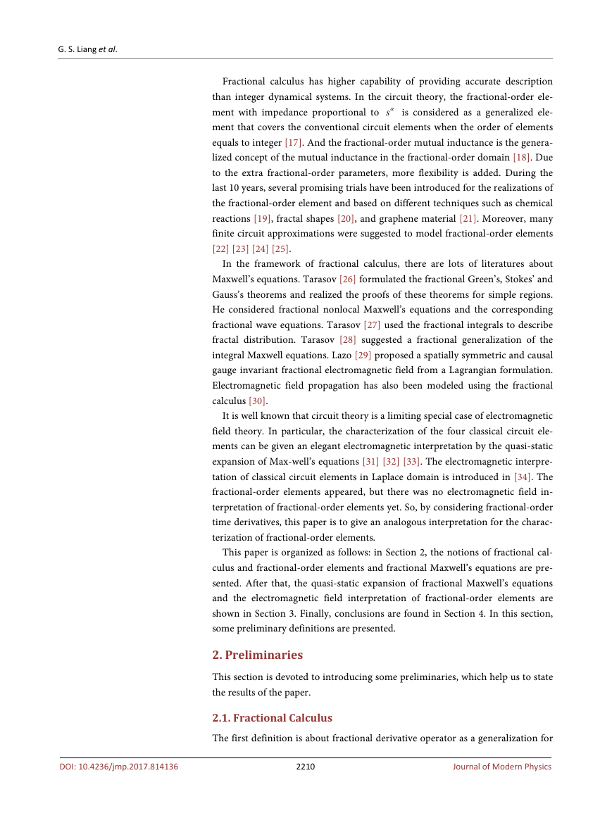
classical derivative operator. There are three kinds of definitions about the frac-
tional derivative, the Riemann-Liouville definition, the Grunwald-Letnikov defi-
nition and the Caputo definition. According to the Caputo definition for frac-
tional derivative, the derivative of order α for function
is given by
( )
t
f
α
tD f
a
( )
t
=
1
(
1
Γ −
)
α
t
∫
0
(
t
)
τ
−
−
fα
′
( )
τ τ
d
, for
)0,1α∈
(
(1)
where
α
tD
a
α
d
α=
t
d
,
( )Γ is Euler’s Gamma function.
2.2. Fractional-Order Elements
The template is used to format your paper and style the text. All margins, column
widths, line spaces, and text fonts are prescribed; please do not alter them. You
may note peculiarities. For example, the head margin in this template measures
proportionately more than is customary. This measurement and others are deli-
berate, using specifications that anticipate your paper as one part of the entire
journals, and not as an independent document. Please do not revise any of the
current designations.
( )
i t
and
( )u t
If
(
are respectively the voltage and current of a fraction-
)0,1α∈
and the pseudo-capacitance Cα, then
( )
α
u t
d
α
t
d
(2)
( )
i t
C
α
=
al-order capacitor with order
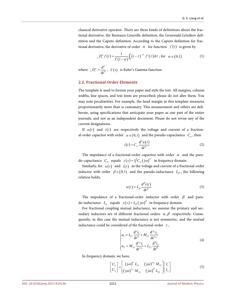
The impedance of a fractional-order capacitor with order α and the pseu-
Similarly, for
( )
z s
do-capacitance Cα equals
( )
and
i t
)0,1β∈
(
( )u t
inductor with order
relation holds,
j
α
(
)
C
α ω
1
in frequency domain.
=
as the voltage and current of a fractional-order
and the pseudo-inductance Lβ, the following
( )
u t
=
L
β
d
( )
β
i t
β
t
d
(3)
The impedance of a fractional-order inductor with order β and pseu-
do-inductance Lα equals
( )
z s
)
β ω=
L
(
j
β
in frequency domain.
For fractional coupling mutual inductance, we assume the primary and sec-
,αβ respectively. Conse-
ondary inductors are of different fractional orders
quently, in this case the mutual inductance is not symmetric, and the mutual
inductance could be considered of the fractional-order γ,
+
M
12
=
L
11
u
1
u M
2
=
α
i
d
1
α
t
d
γ
d
21
d
t
i
1
γ
21
21
+
L
22
i
2
γ
12
γ
d
12
d
t
d
d
β
i
2
β
t
(4)
In frequency domain, we have,
)
(
α
j
ω
)
γ
j
ω
U
U
=
(
21
1
2
γ
12
(
L
11
M
21
)
j
ω
(
)
j
ω
β
12
M
L
22
I
1
I
2
(5)
DOI: 10.4236/jmp.2017.814136
2211
Journal of Modern Physics
�
G. S. Liang et al.
,
,
,
(
)
0,1
21
12
αβγ γ ∈
where
L L M and
tors and mutual inductance,
11
mutual inductance. For the traditional case
represents the matrix equation of the integer-order mutual inductor.
is the fractional order of primary, secondary induc-
21M are primary, secondary,
αβγ γ = , Equation (5)
,
1
22
12
21
12
,
,
,
,
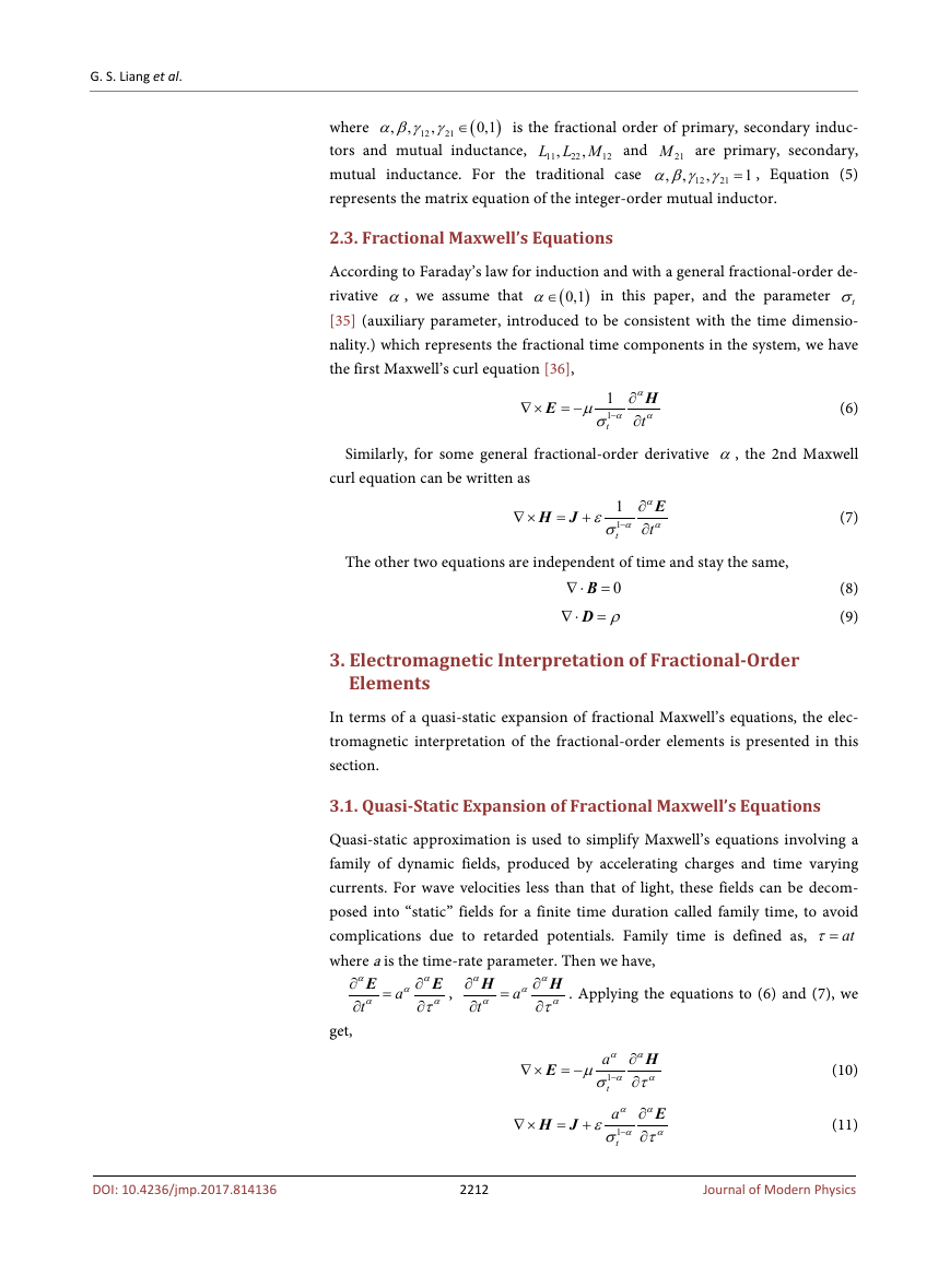
2.3. Fractional Maxwell’s Equations
According to Faraday’s law for induction and with a general fractional-order de-
rivative α, we assume that
tσ
[35] (auxiliary parameter, introduced to be consistent with the time dimensio-
nality.) which represents the fractional time components in the system, we have
the first Maxwell’s curl equation [36],
in this paper, and the parameter
)0,1α∈
(
∇ ×
E
= −
µ
1
1
σ−
α
t
α
H
∂
α
t
∂
(6)
Similarly, for some general fractional-order derivative α, the 2nd Maxwell
curl equation can be written as
∇ ×
H J
= +
ε
1
1
σ−
t
α
E
∂
α α
t
∂
(7)
The other two equations are independent of time and stay the same,
∇ ⋅ =B
=D
∇ ⋅
0
ρ
(8)
(9)
3. Electromagnetic Interpretation of Fractional-Order
Elements
In terms of a quasi-static expansion of fractional Maxwell’s equations, the elec-
tromagnetic interpretation of the fractional-order elements is presented in this
section.
3.1. Quasi-Static Expansion of Fractional Maxwell’s Equations
Quasi-static approximation is used to simplify Maxwell’s equations involving a
family of dynamic fields, produced by accelerating charges and time varying
currents. For wave velocities less than that of light, these fields can be decom-
posed into “static” fields for a finite time duration called family time, to avoid
atτ=
complications due to retarded potentials. Family time is defined as,
where a is the time-rate parameter. Then we have,
=
α
a
α
E ,
∂
ατ
∂
α
H
∂
α
t
∂
=
α
a
α
H . Applying the equations to (6) and (7), we
∂
ατ
∂
α
E
∂
α
t
∂
get,
∇ ×
E
= −
µ
aα α
H
∂
1
α
σ τ−
∂
t
α
(10)
DOI: 10.4236/jmp.2017.814136
2212
Journal of Modern Physics
∇ ×
H J
= +
ε
aα α
E
∂
1
α
σ τ−
∂
t
α
(11)
�
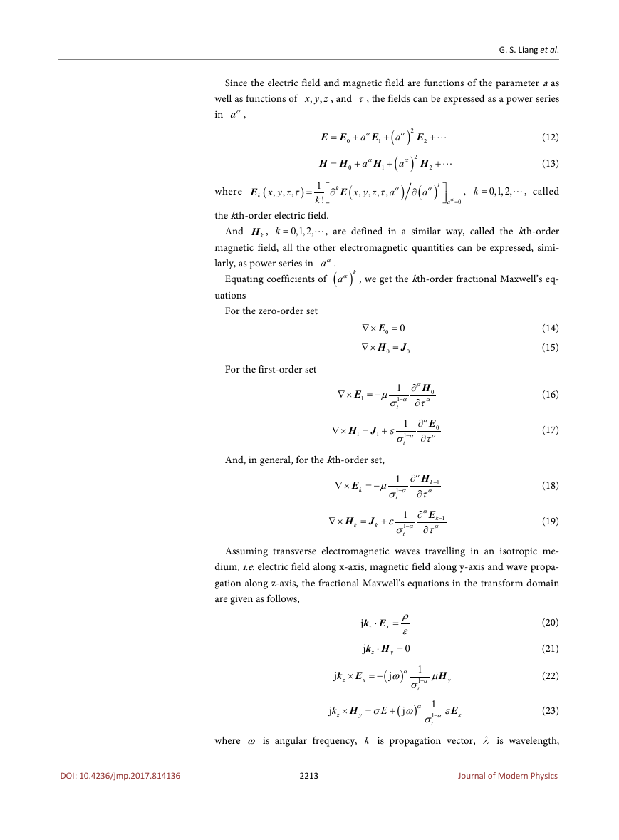
Since the electric field and magnetic field are functions of the parameter a as
x y z , and τ, the fields can be expressed as a power series
,
,
well as functions of
in aα,
G. S. Liang et al.
E E
=
0
+
α
E
a
1
+
(
α
a
(
α
a
+
)2
E (12)
2
)2
H (13)
(
, called
0,1,2,
k =
α
a
,
+
)
2
k
α
a
=
0
+
α
H
a
1
+
x y z
,
,
,
,
τ
α
a
)
∂
H H
=
(
E
x y z
,
,
where
1
k
!
the kth-order electric field.
)
,
τ
=
k
∂
k
E
0
(
k =
0,1,2,
kH ,
And
, are defined in a similar way, called the kth-order
magnetic field, all the other electromagnetic quantities can be expressed, simi-
larly, as power series in aα.
Equating coefficients of (
)kaα , we get the kth-order fractional Maxwell’s eq-
uations
For the zero-order set
∇ ×
∇ ×
0
0
=E
(14)
=H J (15)
0
0
For the first-order set
∇ ×
E
1
= −
µ
α
H
∂
0
α
σ τ−
∂
1
1
t
α
(16)
∇ ×
H J
=
1
+
1
And, in general, for the kth-order set,
ε
α
E
∂
0
σ τ−
α
∂
1
1
t
α
(17)
∇ ×
E
k
= −
µ
1
1
α
−
σ
t
α
H
∂
k
1
−
α
∂
τ
(18)
∇ ×
H J
=
k
+
k
ε
1
1
α
−
σ
t
α
E
∂
k
1
−
α
τ
∂
(19)
Assuming transverse electromagnetic waves travelling in an isotropic me-
dium, i.e. electric field along x-axis, magnetic field along y-axis and wave propa-
gation along z-axis, the fractional Maxwell's equations in the transform domain
are given as follows,
ρ
ε
0
=
k E
j z
⋅
x
=
(20)
j
k H
z
⋅
y
(21)
1
j
αω
1
σ−
t
H (22)
µ
)
α
y
j
k E
z
×
x
= −
(
j
k
z
×
H
y
=
)
σ ω
E
+
(
j
α
1
1
σ−
α
t
E (23)
ε
x
DOI: 10.4236/jmp.2017.814136
where ω is angular frequency, k is propagation vector, λ is wavelength,
2213
Journal of Modern Physics
�
G. S. Liang et al.
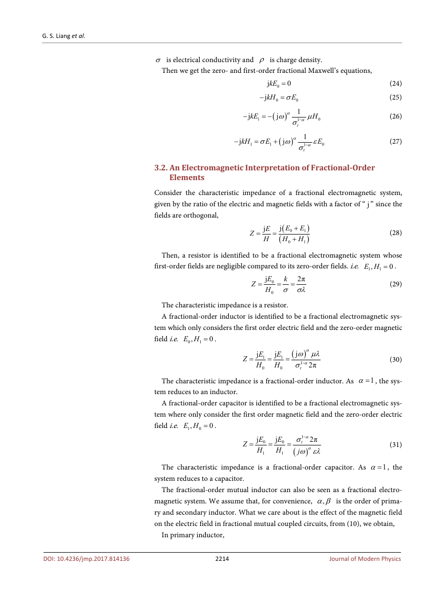
σ is electrical conductivity and ρ is charge density.
Then we get the zero- and first-order fractional Maxwell’s equations,
−
0
0
=
kE = (24)
0
j
Eσ
jkH
(25)
0
1
j
αω
1
σ−
t
(26)
H
µ
(
)
α
0
−
j
kE
1
= −
−
j
kH
1
=
E
σ
1
+
(
α
)
j
ω
1
1
α
σ−
t
E
ε
0
(27)
3.2. An Electromagnetic Interpretation of Fractional-Order
Elements
Consider the characteristic impedance of a fractional electromagnetic system,
given by the ratio of the electric and magnetic fields with a factor of “ j” since the
fields are orthogonal,
Z
=
E
j
H
=
j
(
(
E
E
1
0
H H
+
+
0
1
)
)
(28)
Then, a resistor is identified to be a fractional electromagnetic system whose
first-order fields are negligible compared to its zero-order fields. i.e.
E H = .
0
1
,
1
Z
=
k
E
j
2π
0
H σ σλ
=
=
0
(29)
The characteristic impedance is a resistor.
A fractional-order inductor is identified to be a fractional electromagnetic sys-
tem which only considers the first order electric field and the zero-order magnetic
field i.e.
E H = .
0
0
,
1
Z
=
E
j
1
H
0
=
E
j
1
H
0
=
(
α
)
j
ω µλ
1
σ−
α
2π
t
(30)
The characteristic impedance is a fractional-order inductor. As
1α= , the sys-
tem reduces to an inductor.
A fractional-order capacitor is identified to be a fractional electromagnetic sys-
tem where only consider the first order magnetic field and the zero-order electric
field i.e.
E H = .
0
1
,
0
Z
=
E
j
0
H
1
=
E
j
0
H
1
=
1
−
α
2π
σ
t
(
α
j
ω ελ
)
(31)
The characteristic impedance is a fractional-order capacitor. As
1α= , the
system reduces to a capacitor.
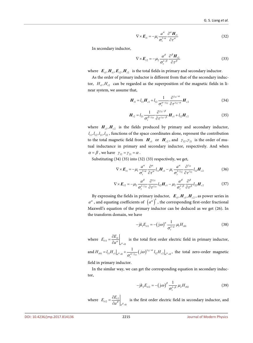
The fractional-order mutual inductor can also be seen as a fractional electro-
,αβ is the order of prima-
magnetic system. We assume that, for convenience,
ry and secondary inductor. What we care about is the effect of the magnetic field
on the electric field in fractional mutual coupled circuits, from (10), we obtain,
In primary inductor,
2214
Journal of Modern Physics
DOI: 10.4236/jmp.2017.814136
�
In secondary inductor,
G. S. Liang et al.
∇ ×
E
t
1
= −
µ
1
αα
H
a
∂
t
1
α
σ τ−
∂
t
α
1
(32)
∇ ×
E
t
2
= −
µ
2
H
a
t
1
β
β
τ−
σ
t
ββ
∂
∂
2
(33)
where
E H E H is the total fields in primary and secondary inductor.
t
,
,
,
1
1
2
2
t
t
t
As the order of primary inductor is different from that of the secondary induc-
H H can be regarded as the superposition of the magnetic fields in li-
,t
1
tor,
near system, we assume that,
2
t
H
t
1
=
l
11
H
c
1
+
l
12
1
−
α γ
σ
12
t
−
γ α
∂
12
τ
∂
γ α
12
−
H
t
2
=
l
21
1
−
β γ
σ
t
21
−
γ β
∂
21
∂
τ
γ β
21
−
H
c
1
+
l
12
H (34)
c
2
H (35)
c
2
c
2
,
21
l
12
H H is the fields produced by primary and secondary inductor,
where
,c
1
l
l
l
, functions of the space coordinates alone, represent the contribution
,
,
22
11
to the total magnetic field from
,γ γ is the order of mu-
12
tual inductance in primary and secondary inductor, respectively. And when
α β=
2cH , and
1cH or
21
= .
γ γ α
12
=
21
, we have
Substituting (34) (35) into (32) (33) respectively, we get,
γ
∂
12
γ
σ τ
∂
12
∇ ×
= −
µ
1
µ
1
l
11
H
E
−
c
1
1
t
α
a
1
γ
−
12
t
l
12
l
22
H (36)
c
2
H (37)
c
2
α
α
a
∂
1
α
α
−
σ τ
∂
t
a
1
t
γ
∂
21
σ τ−
γ
∂
β
γ
21
21
∇ ×
E
t
2
= −
µ
2
l
12
H
c
1
−
µ
2
β
β
a
∂
1
β
−
β
σ τ
∂
t
E H H , as power series in
By expressing the fields in primary inductor,
t
aα, and equating coefficients of (
)kaα , the corresponding first-order fractional
Maxwell’s equation of the primary inductor can be deduced as we get (26). In
the transform domain, we have
c
1
,
,
1
2
c
−
j
k E
t
1
11
= −
(
α
)
1
j
αω
1
σ−
t
µ
1
H
t
01
(38)
where
E
t
11
=
E
∂
t
1
α
a
∂
α
a
=
0
is the total first order electric field in primary inductor,
t
01
=
H
and
l H
11
1
α γ ω
−
σ
t
field in primary inductor.
α
a
=
+
(
c
1
j
12
0
γ α
−
) 12
l H
12
c
2
α
a
=
0
, the total zero-order magnetic
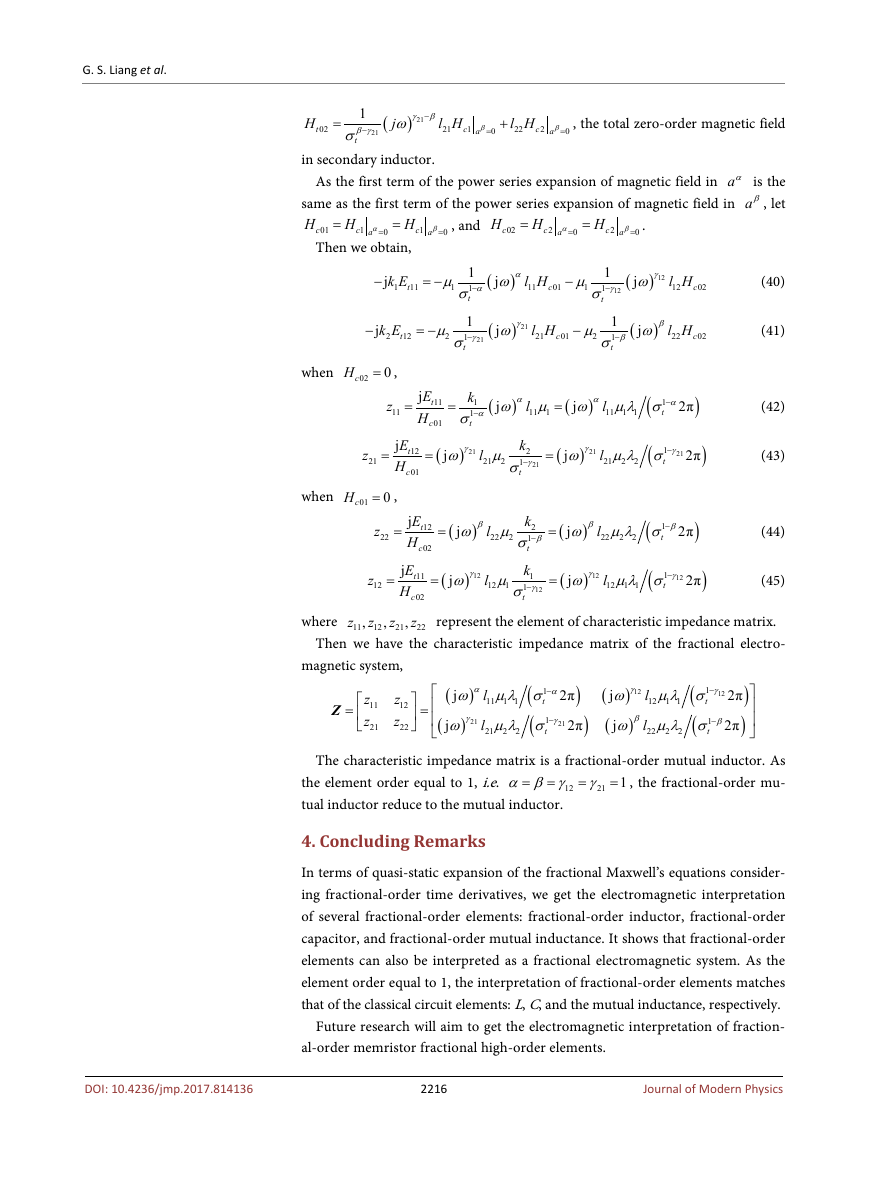
In the similar way, we can get the corresponding equation in secondary induc-
tor,
−
j
k E
t
2
12
= −
(
β
)
1
j
βω
1
σ−
t
µ
2
H
t
02
(39)
DOI: 10.4236/jmp.2017.814136
where
E
t
12
=
E
∂
t
2
β
a
∂
β
=
a
0
is the first order electric field in secondary inductor, and
2215
Journal of Modern Physics
�
G. S. Liang et al.
H
t
02
=
l H
21
c
1
β
=
a
0
+
l H
22
c
2
β
=
a
0
, the total zero-order magnetic field
1
β γ ω
−
σ
t
(
j
21
γ β
−
) 21
in secondary inductor.
As the first term of the power series expansion of magnetic field in aα is the
same as the first term of the power series expansion of magnetic field in aβ, let
H
H
H
H
=
=
, and
.
c
02
c
1
β
=
a
0
c
2
α
a
=
0
c
2
β
=
a
0
=
H
H
c
01
Then we obtain,
α
a
=
=
c
1
0
−
j
k E
t
1
11
= −
µ
1
−
j
k E
t
2
12
= −
µ
2
1
1
α
−
σ
t
1
1
σ−
γ
21
t
(
α
)
j
ω
l H
11
c
01
−
µ
1
1
1
−
γ
σ
12
t
(
j
ω
γ
) 12
l H
12
c
02
(40)
(
γ
21
)
j
ω
l H
21
c
01
−
µ
2
1
1
−
β
σ
t
(
β
)
j
ω
l H
22
c
02
(41)
when
cH = ,
0
02
z
11
=
E
j
t
H
c
11
01
=
k
(
(
1
α
−
2π
α ω µ ω µλ σ
1
t
1
−
σ
t
l
11 1 1
l
11 1
=
)
(
)
α
α
j
j
)
(42)
z
21
=
E
j
t
H
c
12
01
=
(
when
cH = ,
0
01
γ
21
j
ω µ
2
21
l
)
k
2
1
−
γ
σ
21
t
=
(
γ
21
(
1
−
γ
j
ω µλ σ
21
t
l
21
2 2
)
2π
)
(43)
z
22
=
β
j
ω µ
2
l
22
)
=
(
12
02
z
12
=
=
(
γ
12
j
ω µ
1
l
12
)
c
E
j
t
H
E
j
t
H
11
c
02
z
k
2
1
β
−
σ
t
k
1
1
γ
−
σ
12
t
=
(
=
(
β
(
1
β
−
j
ω µλ σ
t
l
22
2 2
)
2π
)
(44)
γ
12
(
1
γ
−
j
ω µλ σ
12
t
l
12
1 1
)
2π
)
(45)
,
where
z
11
z
12
represent the element of characteristic impedance matrix.
Then we have the characteristic impedance matrix of the fractional electro-
z
22
21
,
,
magnetic system,
Z
=
z
11
z
21
z
12
z
22
=
(
α
)
l
11 1 1
(
(
1
α
−
j
2π
ω µλ σ
t
(
)
1
γ
−
j
ω µλ σ
21
t
)
2π
2 2
γ
21
21
l
)
γ
12
l
12
(
(
)
1
γ
−
j
ω µλ σ
12
t
(
(
)
1
β
−
j
ω µλ σ
t
l
22
2 2
1 1
β
)
2π
)
2π
The characteristic impedance matrix is a fractional-order mutual inductor. As
= , the fractional-order mu-
α β γ γ
=
the element order equal to 1, i.e.
12
tual inductor reduce to the mutual inductor.
=
=
21 1
4. Concluding Remarks
In terms of quasi-static expansion of the fractional Maxwell’s equations consider-
ing fractional-order time derivatives, we get the electromagnetic interpretation
of several fractional-order elements: fractional-order inductor, fractional-order
capacitor, and fractional-order mutual inductance. It shows that fractional-order
elements can also be interpreted as a fractional electromagnetic system. As the
element order equal to 1, the interpretation of fractional-order elements matches
that of the classical circuit elements: L, C, and the mutual inductance, respectively.
Future research will aim to get the electromagnetic interpretation of fraction-
al-order memristor fractional high-order elements.
2216
Journal of Modern Physics
DOI: 10.4236/jmp.2017.814136
�


 2023年江西萍乡中考道德与法治真题及答案.doc
 2012年重庆南川中考生物真题及答案.doc
 2013年江西师范大学地理学综合及文艺理论基础考研真题.doc
 2020年四川甘孜小升初语文真题及答案I卷.doc
 2020年注册岩土工程师专业基础考试真题及答案.doc
 2023-2024学年福建省厦门市九年级上学期数学月考试题及答案.doc
 2021-2022学年辽宁省沈阳市大东区九年级上学期语文期末试题及答案.doc
 2022-2023学年北京东城区初三第一学期物理期末试卷及答案.doc
 2018上半年江西教师资格初中地理学科知识与教学能力真题及答案.doc
 2012年河北国家公务员申论考试真题及答案-省级.doc
 2020-2021学年江苏省扬州市江都区邵樊片九年级上学期数学第一次质量检测试题及答案.doc
 2022下半年黑龙江教师资格证中学综合素质真题及答案.doc