logo资料库

sick使用手册.pdf

第1页 / 共127页
第2页 / 共127页
第3页 / 共127页
第4页 / 共127页
第5页 / 共127页
第6页 / 共127页
第7页 / 共127页
第8页 / 共127页
资料共127页,剩余部分请下载后查看
1 About this document
1.1 Function of this document
1.2 Target group
1.3 Depth of information
1.4 Symbology used
2 For your safety
2.1 Authorised personnel
2.2 Correct use
2.3 General safety notes and protective measures
2.3.1 Electrical installation work
2.3.2 Laser radiation from the laser measurement system
2.4 Quick stop and Quick restart
2.4.1 Switching off the LMS
2.4.2 Switching back on the LMS
2.5 Environmental protection
2.5.1 Power consumption
2.5.2 Disposal after final de-commissioning
3 Product description
3.1 Delivery
3.1.1 Contents of the CD-ROM
3.2 Device variants
3.3 Special features of the LMS
3.4 Controls and status indicators
3.4.1 User interface
3.4.2 Status indicators
3.5 Operating principle of the LMS
3.5.1 Scanning range of the LMS
3.5.2 Beam diameter and distance between measured points
3.5.3 Minimum object size
3.5.4 Contamination measurement
3.6 Applications
3.7 Measurement of objects
3.7.1 Basic parameters
3.7.2 Filter
3.7.3 Measured value output
3.7.4 Measured value output for a second reflected pulse
3.8 Field application
3.8.1 Evaluation cases
3.8.2 Evaluation fields
3.8.3 Operator for the evaluation cases on the output
3.9 Inputs and outputs
3.9.1 Digital switching inputs
3.9.2 Encoder inputs
3.9.3 Digital switching outputs
3.9.4 External switching outputs
3.9.5 Logical operators for inputs and outputs
3.9.6 Sabotage outputs
3.10 Data interfaces
3.10.1 Ethernet interface
3.10.2 CAN
3.10.3 Serial host interface
3.10.4 Serial auxiliary interface
3.11 Data communication using messages
3.11.1 Frame and coding for the messages
3.12 Planning
3.12.1 LMS system requirements
3.12.2 Mounting requirements
3.12.3 Distance between LMS and the object/surface to be monitored
4 Mounting
4.1 Overview of the mounting steps
4.2 Preparations for mounting
4.2.1 Components to be mounted
4.2.2 Material and accessories necessary
4.2.3 Necessary tools
4.2.4 Select mounting location
4.3 Mounting steps
4.3.1 Direct mounting
4.3.2 Mounting with mounting kit 1a or 1b
4.3.3 Mounting with mounting kit 2 and 3
4.3.4 Mounting the LMS111/LMS151 with weather protection hood
4.3.5 Using multiple LMS laser measurement systems
4.4 Dismanteling the system
5 Electrical installation
5.1 Overview of the installation steps
5.2 Connections of the LMS
5.2.1 Connections of the LMS100
5.2.2 Connections of the LMS120
5.2.3 Connections of the LMS111/LMS151
5.3 Preparing the electrical installation
5.3.1 Supply voltage
5.3.2 Wire cross-sections
5.3.3 General conditions for the data interfaces
5.4 Perform electrical installation on the LMS
5.4.1 Equipment
5.4.2 Connection on the auxiliary interface and the Ethernet interface of the LMS100…LMS151
5.4.3 Connecting the system plug on the LMS100 and LMS120
5.4.4 Connecting the round M12 plug connector on the LMS111/LMS151
5.4.5 Wiring of inputs and outputs on the LMS
6 Commissioning and configuration
6.1 Overview of the commissioning steps
6.2 SOPAS ET configuration software
6.2.1 System requirements for SOPAS ET
6.2.2 Installation of SOPAS ET
6.2.3 SOPAS ET default setting
6.3 Establish communication with the LMS
6.3.1 Connect the data interfaces
6.3.2 Starting SOPAS ET and opening the scan assistant
6.3.3 Configuring the serial connection
6.3.4 Configuring the Ethernet connection
6.3.5 Performing scan
6.4 Initial commissioning
6.4.1 Configuring the LMS
6.5 Connection and test measurement
7 Maintenance
7.1 Maintenance during operation
7.1.1 Cleaning the optics cover
7.2 Exchanging an LMS
8 Troubleshooting
8.1 In the event of faults or errors
8.2 Error displays of the LEDs
8.3 Indications of the 7-segment display
8.4 Detailed error analysis
8.4.1 Field evaluation monitor
8.4.2 Field evaluation logging
9 Technical specifications
9.1 Data sheet LMS laser measurement system
9.2 Dimensional drawings
9.2.1 Dimensional drawing LMS100/LMS120
9.2.2 Dimensional drawing LMS111/LMS151
9.2.3 Dimensional drawings, mounting kits
9.2.4 Dimensional drawings, weather protection hoods
10 Annex
10.1 Overview of the annexes
10.2 Messages
10.3 Ordering information
10.3.1 Consumables
10.4 Glossary
10.5 EC Declaration of Conformity
SICK

O P E R AT I N G I N S T R U C T I O N S LMS100/111/120/151 Laser Measurement Systems In full view in all weathers – compact and economical
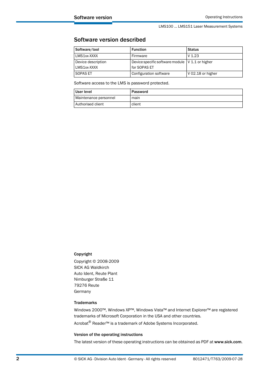
Software version Operating Instructions LMS100 … LMS151 Laser Measurement Systems Software version described Function Software/tool LMS1xx-XXXX Firmware Device specific software module Device description for SOPAS ET LMS1xx5XXXX SOPAS ET Configuration software Status V 1.23 V 1.1 or higher V 02.18 or higher Software access to the LMS is password protected. User level Maintenance personnel Authorised client Password main client Copyright Copyright © 2008-2009 SICK AG Waldkirch Auto Ident, Reute Plant Nimburger Straße 11 79276 Reute Germany Trademarks Windows 2000™, Windows XP™, Windows Vista™ and Internet Explorer™ are registered trademarks of Microsoft Corporation in the USA and other countries. Acrobat® Reader™ is a trademark of Adobe Systems Incorporated. Version of the operating instructions The latest version of these operating instructions can be obtained as PDF at www.sick.com. 2 © SICK AG · Division Auto Ident · Germany · All rights reserved 8012471/T763/2009-07-28
Operating Instructions LMS100 … LMS151 Contents Table of contents About this document .......................................................................................................9 1 Function of this document .......................................................................................... 9 1.1 Target group ................................................................................................................ 9 1.2 Depth of information ................................................................................................... 9 1.3 Symbology used ........................................................................................................10 1.4 For your safety .............................................................................................................. 11 2 Authorised personnel ................................................................................................11 2.1 Correct use ................................................................................................................11 2.2 General safety notes and protective measures ......................................................12 2.3 Quick stop and Quick restart ....................................................................................14 2.4 Environmental protection .........................................................................................14 2.5 Product description ...................................................................................................... 16 3 Delivery ......................................................................................................................16 3.1 Device variants ..........................................................................................................16 3.2 Special features of the LMS ..................................................................................... 18 3.3 Controls and status indicators .................................................................................18 3.4 Operating principle of the LMS .................................................................................20 3.5 3.6 Applications ...............................................................................................................28 3.7 Measurement of objects ........................................................................................... 28 3.8 Field application ........................................................................................................34 3.9 Inputs and outputs ....................................................................................................38 3.10 Data interfaces ..........................................................................................................39 3.11 Data communication using messages .................................................................... 41 3.12 Planning .....................................................................................................................42 4 Mounting ........................................................................................................................ 45 Overview of the mounting steps ...............................................................................45 4.1 4.2 Preparations for mounting ........................................................................................45 4.3 Mounting steps ..........................................................................................................45 Dismanteling the system ..........................................................................................52 4.4 Electrical installation ................................................................................................... 53 5 Overview of the installation steps ............................................................................53 5.1 5.2 Connections of the LMS ............................................................................................53 Preparing the electrical installation .........................................................................58 5.3 Perform electrical installation on the LMS ..............................................................59 5.4 Commissioning and configuration ............................................................................. 66 6 6.1 Overview of the commissioning steps .....................................................................66 SOPAS ET configuration software ............................................................................66 6.2 Establish communication with the LMS ..................................................................67 6.3 6.4 Initial commissioning ................................................................................................69 Connection and test measurement .........................................................................71 6.5 7 Maintenance ................................................................................................................. 72 7.1 Maintenance during operation .................................................................................72 7.2 Exchanging an LMS ...................................................................................................72 Troubleshooting ............................................................................................................ 73 8 In the event of faults or errors ..................................................................................73 8.1 Error displays of the LEDs ........................................................................................73 8.2 8.3 Indications of the 7-segment display .......................................................................74 Detailed error analysis ..............................................................................................74 8.4 8012471/T763/2009-07-28 © SICK AG · Division Auto Ident · Germany · All rights reserved 3
Contents Operating Instructions LMS100 … LMS151 Laser Measurement Systems Technical specifications .............................................................................................. 75 9 Data sheet LMS laser measurement system ......................................................... 75 9.1 Dimensional drawings .............................................................................................. 80 9.2 Annex ............................................................................................................................. 85 10 10.1 Overview of the annexes .......................................................................................... 85 10.2 Messages .................................................................................................................. 85 10.3 Ordering information .............................................................................................. 106 10.4 Glossary ................................................................................................................... 107 10.5 EC Declaration of Conformity ................................................................................. 108 4 © SICK AG · Division Auto Ident · Germany · All rights reserved 8012471/T763/2009-07-28
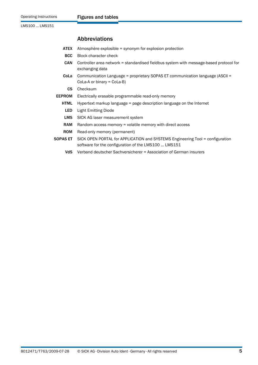
Operating Instructions LMS100 … LMS151 Figures and tables Abbreviations Atmosphère explosible = synonym for explosion protection ATEX BCC Block character check CAN Controller area network = standardised fieldbus system with message-based protocol for CoLa exchanging data Communication Language = proprietary SOPAS ET communication language (ASCII = CoLa5A or binary = CoLa5B) CS Checksum EEPROM Electrically erasable programmable read-only memory HTML Hypertext markup language = page description language on the Internet LED Light Emitting Diode LMS SICK AG laser measurement system RAM Random access memory = volatile memory with direct access ROM Read-only memory (permanent) SOPAS ET SICK OPEN PORTAL for APPLICATION and SYSTEMS Engineering Tool = configuration software for the configuration of the LMS100 … LMS151 VdS Verband deutscher Sachversicherer = Association of German insurers 8012471/T763/2009-07-28 © SICK AG · Division Auto Ident · Germany · All rights reserved 5
Figures and tables Operating Instructions LMS100 … LMS151 Laser Measurement Systems Tables Target groups of this document .............................................................................. 9 Tab. 1: Authorised personnel .............................................................................................11 Tab. 2: Delivery ...................................................................................................................16 Tab. 3: Device variants .......................................................................................................16 Tab. 4: Special features of the LMS variants ...................................................................18 Tab. 5: Tab. 6: Meaning of the LEDs ..............................................................................................19 Input combination examples .................................................................................35 Tab. 7: Tab. 8: Frame for the messages with ASCII coding ..........................................................42 Tab. 9: Frame for the messages with binary coding ........................................................42 Tab. 10: Beam diameter at different distances from the LMS ..........................................44 Tab. 11: Terminal assignment of the LMS100 ...................................................................54 Tab. 12: Pin assignment of the “Ethernet” connection on the LMS100 ..........................54 Tab. 13: Pin assignment of the “Auxiliary interface” connection on the LMS100 ...........55 Tab. 14: Terminal assignment of the LMS120 ...................................................................55 Tab. 15: Pin assignment of the “Ethernet” connection on the LMS120 ..........................56 Tab. 16: Pin assignment of the “Auxiliary interface” connection on the LMS120 ...........56 Tab. 17: Pin assignment of the “Power” connection on the LMS111/LMS151 ..............56 Tab. 18: Pin assignment of the “RS5232” connection on the LMS111/LMS151 ............56 Tab. 19: Pin assignment of the “I/O” connection on the LMS111/LMS151 ...................57 Tab. 20: Pin assignment of the “Ethernet” connection on the LMS111/LMS151 ..........57 Tab. 21: Pin assignment of the “Auxiliary interface” connection on the LMS111/LMS151 ......................................................................................57 Tab. 22: Maximum cable lengths for the data interfaces ..................................................58 Tab. 23: SOPAS ET default setting .......................................................................................67 Tab. 24: Connect the data interfaces ..................................................................................67 Tab. 25: Passwords ..............................................................................................................70 Tab. 26: Error displays of the LEDs .....................................................................................73 Tab. 27: Indications of the 75segment display ....................................................................74 Tab. 28: Data sheet LMS100 … LMS151 ...........................................................................75 Tab. 29: Variable types .........................................................................................................85 Tab. 30: Hash values of the passwords ..............................................................................96 Tab. 31: Consumables ....................................................................................................... 106 6 © SICK AG · Division Auto Ident · Germany · All rights reserved 8012471/T763/2009-07-28
Operating Instructions LMS100 … LMS151 Figures and tables Figures Laser output aperture of the LMS ........................................................................ 13 Fig. 1: Laser warning label on the LMS ........................................................................... 14 Fig. 2: Device variants ...................................................................................................... 17 Fig. 3: Status indicators .................................................................................................... 19 Fig. 4: Measuring principle of the LMS ........................................................................... 20 Fig. 5: Principle of operation for pulse propagation time measurement ...................... 20 Fig. 6: Reflection of the laser beam at the surface of an object ................................... 21 Fig. 7: Reflection angle ..................................................................................................... 21 Fig. 8: Fig. 9: Degree of reflection ............................................................................................... 22 Fig. 10: Mirror surfaces ...................................................................................................... 22 Fig. 11: Object smaller than diameter of the laser beam ................................................ 22 Fig. 12: Scanning range of the LMS100/LMS111/LMS120 as a function of the target remission ................................................................... 23 Fig. 13: Scanning range of the LMS151 as a function of the target remission ............. 23 Fig. 14: Beam expansion .................................................................................................... 24 Fig. 15: Schematic layout of the distance between measured points at different angular resolutions ............................................................................ 24 Fig. 16: Beam diameter and distance between measured points at 0 to 20 m (0 to 65.62 ft) .................................................................................. 25 Fig. 17: Beam diameter and distance between measured points of LMS151 at 0 to 50 m (0 to 164.04 ft) ................................................................................ 26 Fig. 18: Minimum object size for detection ....................................................................... 26 Fig. 19: Measured value message request ....................................................................... 30 Fig. 20: Continuous measured value output ..................................................................... 31 Fig. 21: Principle of operation of the measurement of the second reflected pulse ....... 32 Fig. 22: Shading of reflections ........................................................................................... 33 Fig. 23: Principle of the field application ........................................................................... 34 Fig. 24: Protection against tampering due to shading and glare .................................... 36 Examples of different evaluation field shapes .................................................... 37 Fig. 25: Fig. 26: Logical operators for inputs and outputs ............................................................. 39 Fig. 27: Increase in the size of the beam and safety supplement .................................. 43 Fig. 28: Direct mounting ..................................................................................................... 46 Fig. 29: Mounting with mounting kit 1a ............................................................................. 47 Fig. 30: Mounting with mounting kit 1b ............................................................................ 47 Fig. 31: Mounting with mounting kit 2 and 3 .................................................................... 48 Fig. 32: Weather protection hood 190° ............................................................................ 49 Fig. 33: Weather protection hood 270° ............................................................................ 49 Fig. 34: Mounting kit for the weather protection hood ..................................................... 50 Fig. 35: Quick-action mounting kit for the weather protection hood ............................... 50 Fig. 36: Placement of two LMS opposed to each other ................................................... 51 Fig. 37: Crosswise placement of two LMS ........................................................................ 51 8012471/T763/2009-07-28 © SICK AG · Division Auto Ident · Germany · All rights reserved 7
Figures and tables Operating Instructions LMS100 … LMS151 Laser Measurement Systems Placement of two LMS with parallel offset ...........................................................51 Fig. 38: Placement of two LMS with parallel offset, one of these upside down .............52 Fig. 39: Placement of two LMS upside down, parallel offset ...........................................52 Fig. 40: Placement of two LMS with parallel offset, one of these upside down .............52 Fig. 41: LMS100 … LMS151: RS5232 connection at the auxiliary interface ...................59 Fig. 42: LMS100 … LMS151: Ethernet connection using the Ethernet cable ................59 Fig. 43: LMS111/LMS151: connection of the voltage supply .........................................61 Fig. 44: LMS111/LMS151: “RS5232” connection ............................................................61 Fig. 45: LMS111/LMS151: “I/O” connection ....................................................................62 Fig. 46: Fig. 47: Connecting digital inputs as non-floating .............................................................62 Fig. 48: Connecting digital inputs as floating ....................................................................62 Fig. 49: Wiring encoder inputs ............................................................................................63 Fig. 50: Connection of the outputs to a PLC, non-floating (active high) ..........................63 Fig. 51: Connection of the outputs to a PLC, non-floating (active low) ............................63 Fig. 52: Connection of the outputs to a PLC, floating (active high) ..................................64 Fig. 53: Connection of the outputs to a PLC, floating (active low) ...................................64 Fig. 54: Connection to an object protection system .........................................................64 Fig. 55: Connection to an object protection system, resistance monitored ....................64 Fig. 56: Wiring of the CAN interface ...................................................................................65 Fig. 57: Wiring the RS5232 interface ..................................................................................65 Fig. 58: Principle of data storage .......................................................................................69 Fig. 59: Dimensional drawing LMS100/LMS120 .............................................................80 Fig. 60: Dimensional drawing LMS111/LMS151 .............................................................81 Fig. 61: Dimensional drawing, mounting kit 1a .................................................................82 Fig. 62: Dimensional drawing, mounting kit 1b .................................................................82 Fig. 63: Dimensional drawing, mounting kit 2 ...................................................................83 Fig. 64: Dimensional drawing, mounting kit 3 ...................................................................83 Fig. 65: Dimensional drawing weather protection hood 190° .........................................84 Fig. 66: Dimensional drawing weather protection hood 270° .........................................84 Fig. 67: Illustration containing the EC Declaration of Conformity ................................. 108 8 © SICK AG · Division Auto Ident · Germany · All rights reserved 8012471/T763/2009-07-28
分享到:
收藏