Abaqus Training Seminar
for Machining Simulation
Mohamed Elkhateeb
Date: Sept. 29. 2017
PPPUUURRRDDDUUUEEE ––– CCCLLLAAAMMM
http://engineering.purdue.edu/CLM/
Purdue University : Center for Laser-based Manufacturing
PPPUUURRRDDDUUUEEE ––– CCCLLLAAAMMM
�
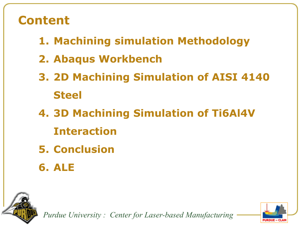
Content
1. Machining simulation Methodology
2. Abaqus Workbench
3. 2D Machining Simulation of AISI 4140
Steel
4. 3D Machining Simulation of Ti6Al4V
Interaction
5. Conclusion
6. ALE
Purdue University : Center for Laser-based Manufacturing
PPPUUURRRDDDUUUEEE ––– CCCLLLAAAMMM
�
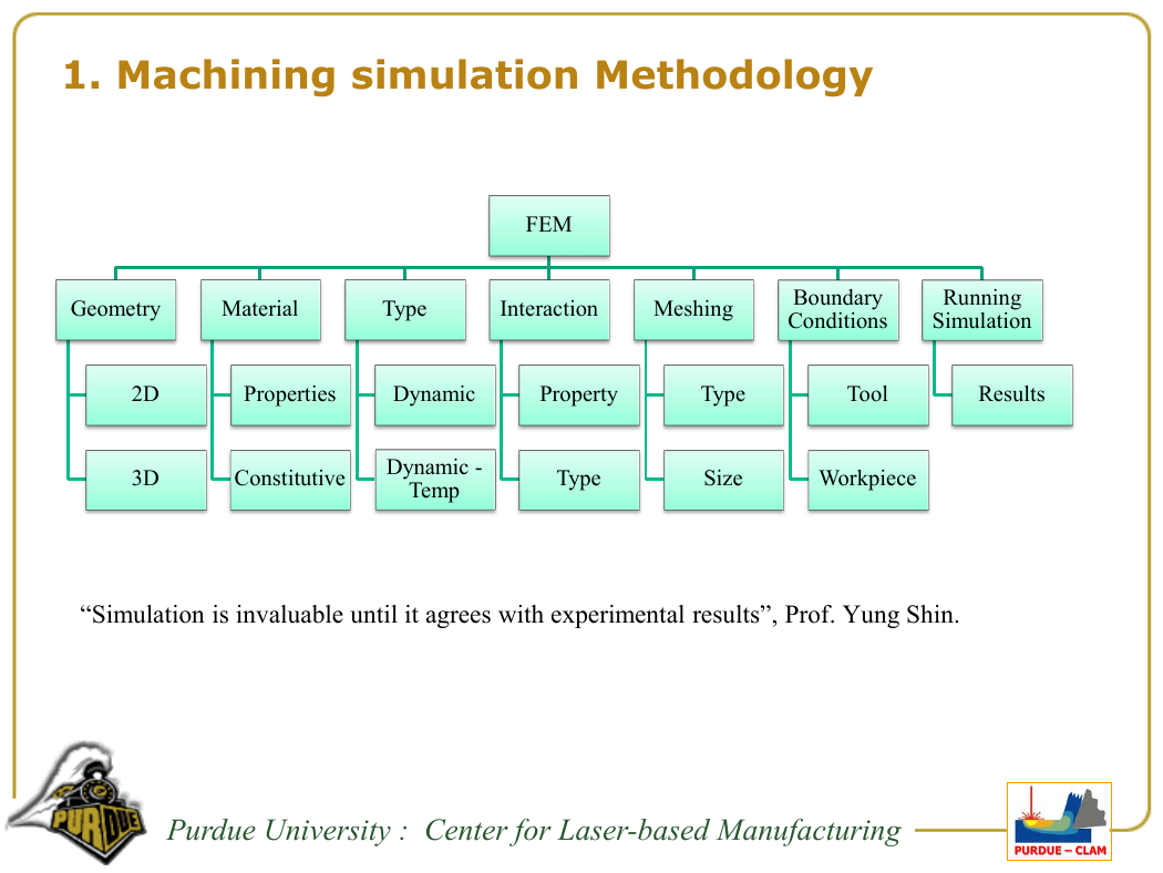
1. Machining simulation Methodology
FEM
Geometry
Material
Type
Interaction
Meshing
Boundary
Conditions
Running
Simulation
2D
3D
Properties
Dynamic
Property
Type
Tool
Results
Constitutive
Dynamic -
Temp
Type
Size
Workpiece
“Simulation is invaluable until it agrees with experimental results”, Prof. Yung Shin.
Purdue University : Center for Laser-based Manufacturing
PPPUUURRRDDDUUUEEE ––– CCCLLLAAAMMM
�
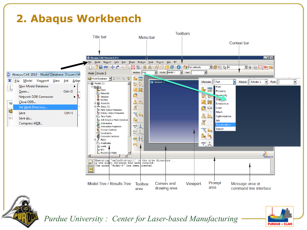
2. Abaqus Workbench
Purdue University : Center for Laser-based Manufacturing
PPPUUURRRDDDUUUEEE ––– CCCLLLAAAMMM
�
3. 2D Machining Simulation of AISI 4140 Steel [1]
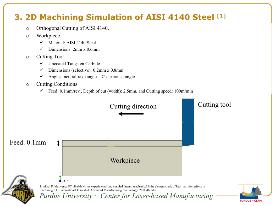
o Orthogonal Cutting of AISI 4140.
o Workpiece
Material: AISI 4140 Steel
Dimensions: 2mm x 0.6mm
o Cutting Tool
Uncoated Tungsten Carbide
Dimensions (selective): 0.2mm x 0.8mm
Angles: neutral rake angle – 7o clearance angle
o Cutting Conditions
Feed: 0.1mm/rev , Depth of cut (width): 2.5mm, and Cutting speed: 100m/min
Cutting direction
Cutting tool
Workpiece
1. Akbar F, Mativenga PT, Sheikh M. An experimental and coupled thermo-mechanical finite element study of heat partition effects in
machining. The International Journal of Advanced Manufacturing Technology. 2010;46(5-8):
Purdue University : Center for Laser-based Manufacturing
PPPUUURRRDDDUUUEEE ––– CCCLLLAAAMMM
Feed: 0.1mm
�
3.1 Geometry Creation
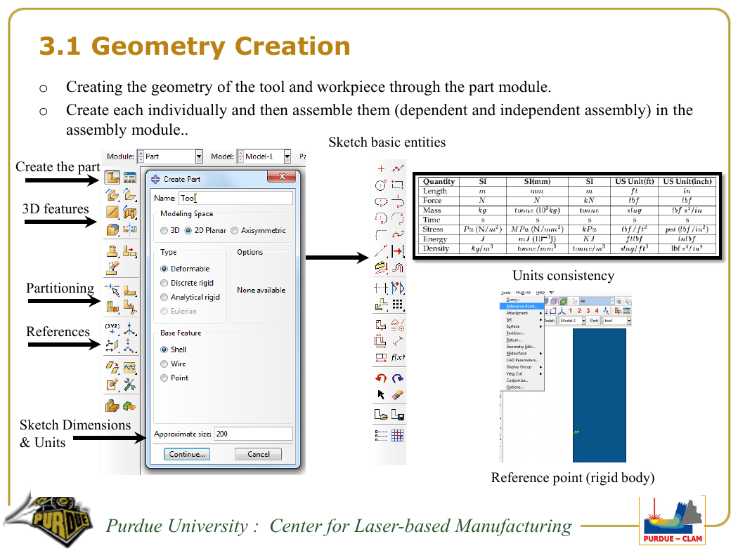
o Creating the geometry of the tool and workpiece through the part module.
o Create each individually and then assemble them (dependent and independent assembly) in the
assembly module..
Create the part
3D features
Partitioning
References
Sketch Dimensions
& Units
Sketch basic entities
Units consistency
Reference point (rigid body)
Purdue University : Center for Laser-based Manufacturing
PPPUUURRRDDDUUUEEE ––– CCCLLLAAAMMM
�
3.2 Material
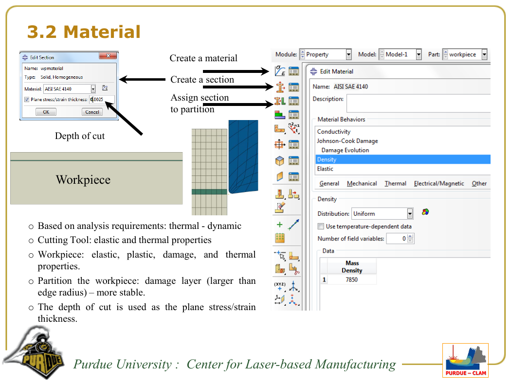
Depth of cut
Workpiece
Create a material
Create a section
Assign section
to partition
o Based on analysis requirements: thermal - dynamic
o Cutting Tool: elastic and thermal properties
o Workpiece: elastic, plastic, damage, and thermal
properties.
o Partition the workpiece: damage layer (larger than
edge radius) – more stable.
o The depth of cut is used as the plane stress/strain
thickness.
Purdue University : Center for Laser-based Manufacturing
PPPUUURRRDDDUUUEEE ––– CCCLLLAAAMMM
�
3.2 Material
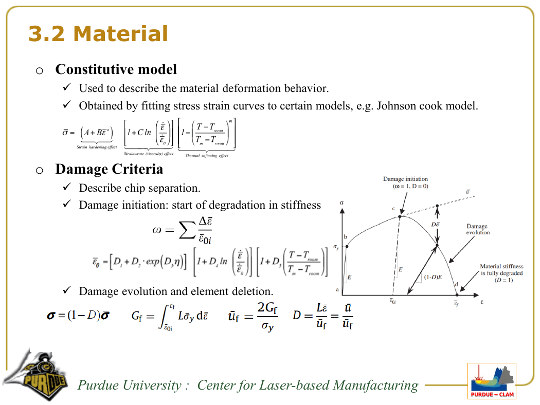
o Constitutive model
Used to describe the material deformation behavior.
Obtained by fitting stress strain curves to certain models, e.g. Johnson cook model.
o Damage Criteria
Describe chip separation.
Damage initiation: start of degradation in stiffness
Damage evolution and element deletion.
Purdue University : Center for Laser-based Manufacturing
PPPUUURRRDDDUUUEEE ––– CCCLLLAAAMMM
�


 2023年江西萍乡中考道德与法治真题及答案.doc
 2012年重庆南川中考生物真题及答案.doc
 2013年江西师范大学地理学综合及文艺理论基础考研真题.doc
 2020年四川甘孜小升初语文真题及答案I卷.doc
 2020年注册岩土工程师专业基础考试真题及答案.doc
 2023-2024学年福建省厦门市九年级上学期数学月考试题及答案.doc
 2021-2022学年辽宁省沈阳市大东区九年级上学期语文期末试题及答案.doc
 2022-2023学年北京东城区初三第一学期物理期末试卷及答案.doc
 2018上半年江西教师资格初中地理学科知识与教学能力真题及答案.doc
 2012年河北国家公务员申论考试真题及答案-省级.doc
 2020-2021学年江苏省扬州市江都区邵樊片九年级上学期数学第一次质量检测试题及答案.doc
 2022下半年黑龙江教师资格证中学综合素质真题及答案.doc