Microsoft Pen Protocol V2.0
HBI: Microsoft Confidential
Shared under NDA
For EEAP
© 2017 Microsoft
12-22-17
Document Revision 1.0
�
Table of Contents
Introduction ................................................................................................................... 5
Timing/Frequency Accuracy ......................................................................................... 6
Pen Electrodes ............................................................................................................... 7
Pen State Machine ........................................................................................................ 8
Pen Protocol .................................................................................................................. 9
Physical Layer .............................................................................................................................. 9
Transmitted Signal ....................................................................................................................... 9
5.1.2 Modulation .................................................................................................................................. 9
1
2
3
4
5
5.1
5.1.1
5.1.3
5.2
5.2.1
5.2.2
5.2.3
5.3
6
6.1
6.2
Frequencies ................................................................................................................................. 9
Link Layer ................................................................................................................................... 10
Transmitted Frame .................................................................................................................... 10
Symbols ..................................................................................................................................... 10
State Specific Frames ................................................................................................................ 14
Data Layer .................................................................................................................................. 19
HBI: Microsoft Confidential
Shared under NDA
For EEAP
© 2017 Microsoft
12-22-17
Electro Static Design Guidelines ................................................................................ 25
Materials stack up ..................................................................................................................... 25
Critical dimensions .................................................................................................................... 25
5.3.1 Digital LF Data (same as Microsoft Pen Protocol V1.x) ............................................................. 19
5.3.2 Digital HF Data ........................................................................................................................... 20
5.3.3 Pressure Data ............................................................................................................................ 23
List of Tables
Table 1 – Revision History ..................................................................................................................... 4
Table 2 – Timing/Frequency Accuracy ................................................................................................ 6
Table 3 – Symbols Timing and Frequencies ..................................................................................... 11
Table 4 – Pressure and Digital HF Inter Symbol Timing ................................................................. 12
Table 5 – MFSK Pressure Frequencies ............................................................................................... 13
Table 6 – Front Ink Frame Transmitted Symbols ............................................................................. 14
Table 7 – Front Hover Frame Transmitted Symbols ........................................................................ 15
Microsoft Pen Protocol V2.0, Revision 1.0
Microsoft Proprietary and Confidential, Released under NDA
Page 2
�
Table 8 – Tail Hover Frame Transmitted Symbols ........................................................................... 16
Table 9 – Front Ink Frame Transmitted Symbols ............................................................................. 17
Table 10 – Buttons bits mapping ....................................................................................................... 23
Table 11 – Data Type Priority ............................................................................................................. 23
Table 12 – ES Critical Dimensions ...................................................................................................... 26
List of Figures
Figure 1 – Multiple Tx phase error ....................................................................................................... 6
Figure 2 – Tip and Ring Electrodes (illustration only) ........................................................................ 7
Figure 3 – Pen State Machine ............................................................................................................... 8
Figure 4 – Tip and Ring Signal Waveform .......................................................................................... 9
Figure 5 – Microsoft Pen Protocol V2.0 General Frame .................................................................. 10
Figure 6 – Front Ink Frame .................................................................................................................. 14
Figure 7 – Front Hover Frame ............................................................................................................. 15
Figure 8 – Tail Hover ............................................................................................................................ 16
HBI: Microsoft Confidential
Shared under NDA
For EEAP
© 2017 Microsoft
12-22-17
Figure 9 – Tail Erase ............................................................................................................................. 16
Figure 10 – Digital LF Data Byte (8-bits) ........................................................................................... 19
Figure 11 – Byte Ordering (including error correction) ................................................................... 19
Figure 12 – Data for Pen ID ................................................................................................................ 20
Figure 13 – Data for Battery Low Indication ..................................................................................... 20
Figure 14 – Digital HF Data bits mapping ......................................................................................... 21
Figure 15 – Digital HF Data Bytes (16-bits) ....................................................................................... 21
Figure 16 – Digital HF Hamming calculation .................................................................................... 21
Figure 17 – Digital HF Messages Mapping ....................................................................................... 21
Figure 18 – Aware bit example ........................................................................................................... 22
Figure 19 – Pen ID bits mapping ........................................................................................................ 22
Figure 20 – Front Ink State Pressure Data Mapping ........................................................................ 24
Figure 21 – Front Hover to Ink Pressure Data Mapping ................................................................. 24
Figure 22 – Front Ink to Hover Pressure Data Mapping ................................................................. 24
Microsoft Pen Protocol V2.0, Revision 1.0
Microsoft Proprietary and Confidential, Released under NDA
Page 3
�
Figure 23 – Front Ink to Hover Pressure Data Mapping – First Frame exception ....................... 24
Figure 24 – Tail Erase Pressure Data Mapping ................................................................................. 25
Figure 25 – Materials Stack Up ........................................................................................................... 25
Figure 26 – Front Pen critical dimensions ......................................................................................... 26
Document Revision History
Revision
Date
Author
Description
1.0
June 24, 2017
Creation
Mishalov, Uri Ron
Amir Zyskind, Vadim
Table 1 – Revision History
HBI: Microsoft Confidential
Shared under NDA
For EEAP
© 2017 Microsoft
12-22-17
Microsoft Proprietary and Confidential
Released under NDA
Microsoft Pen Protocol V2.0, Revision 1.0
Microsoft Proprietary and Confidential, Released under NDA
Page 4
�
1 Introduction
This document presents the Microsoft Pen protocol specifications and requirements.
The protocol embeds the following modes:
1. Microsoft Pen Protocol V1/V1.5/V1.51: Supports Tip and Tail electrodes transmission
2. Microsoft Pen Protocol V2.0: Supports Tip, Ring and Tail electrodes transmission
All the information in this document contains Microsoft proprietary and
confidential information and is released under NDA.
HBI: Microsoft Confidential
Shared under NDA
For EEAP
© 2017 Microsoft
12-22-17
Microsoft Pen Protocol V2.0, Revision 1.0
Microsoft Proprietary and Confidential, Released under NDA
Page 5
�
2 Timing/Frequency Accuracy
The table below summarizes the accuracy of all the data provided throughout this
document –
Parameter
Functionality
Nominal Frequency Accuracy
Frame timing Clock All frame timing data
32.7707 kHz
±20 PPM
Tx Frequency
Transmitted frequency data
18 – 210 kHz (2)
±1500 PPM
<±500 nsec
Multiple Tx Phase
Error(1)
Table 2 – Timing/Frequency Accuracy
Phase error between
transmitting electrodes
HBI: Microsoft Confidential
Shared under NDA
For EEAP
© 2017 Microsoft
12-22-17
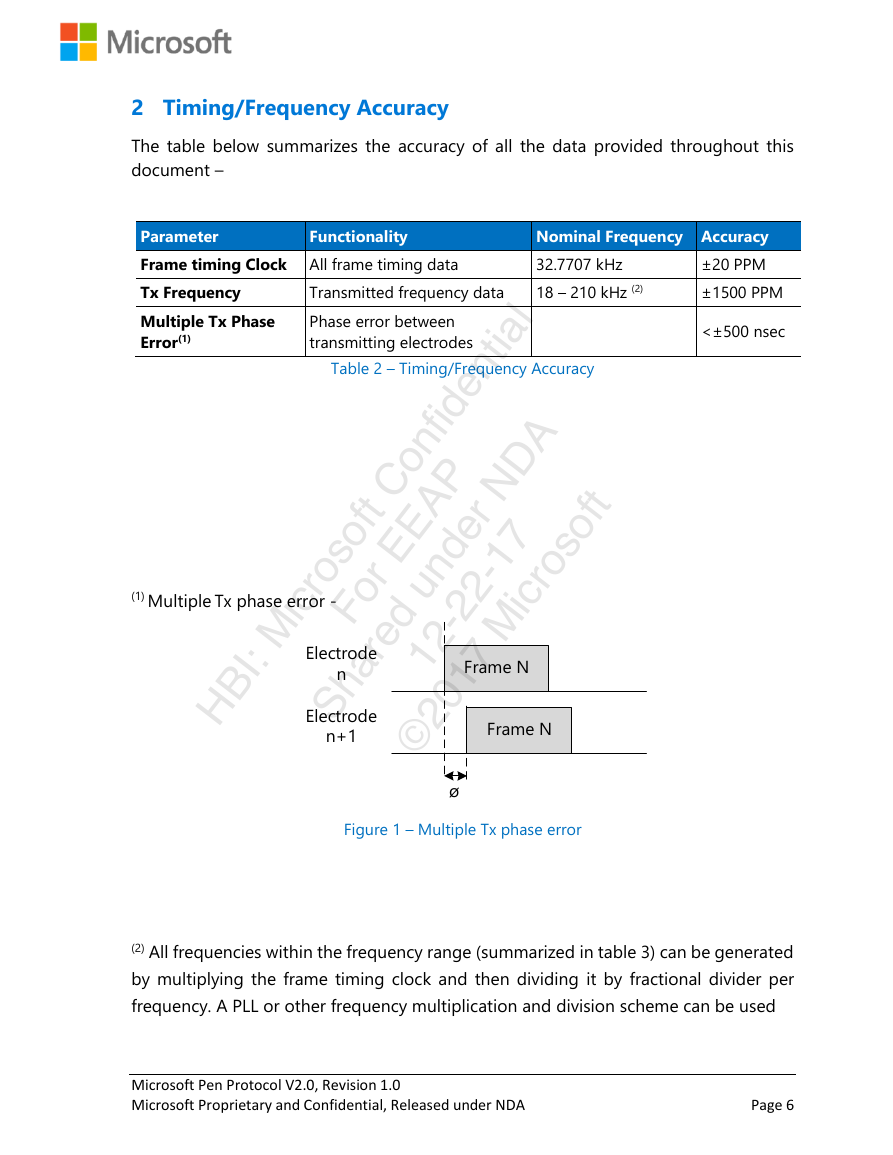
(1) Multiple Tx phase error -
Figure 1 – Multiple Tx phase error
(2) All frequencies within the frequency range (summarized in table 3) can be generated
by multiplying the frame timing clock and then dividing it by fractional divider per
frequency. A PLL or other frequency multiplication and division scheme can be used
Microsoft Pen Protocol V2.0, Revision 1.0
Microsoft Proprietary and Confidential, Released under NDA
Page 6
Frame NFrame Nø Electrode nElectrode n+1�
3 Pen Electrodes
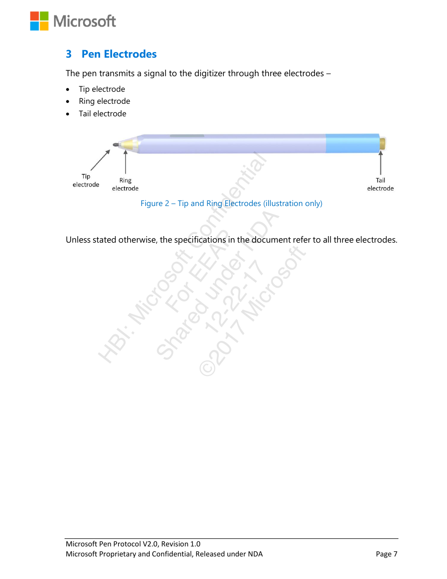
The pen transmits a signal to the digitizer through three electrodes –
Tip electrode
Ring electrode
Tail electrode
Unless stated otherwise, the specifications in the document refer to all three electrodes.
Figure 2 – Tip and Ring Electrodes (illustration only)
HBI: Microsoft Confidential
Shared under NDA
For EEAP
© 2017 Microsoft
12-22-17
Microsoft Pen Protocol V2.0, Revision 1.0
Microsoft Proprietary and Confidential, Released under NDA
Page 7
�
4 Pen State Machine
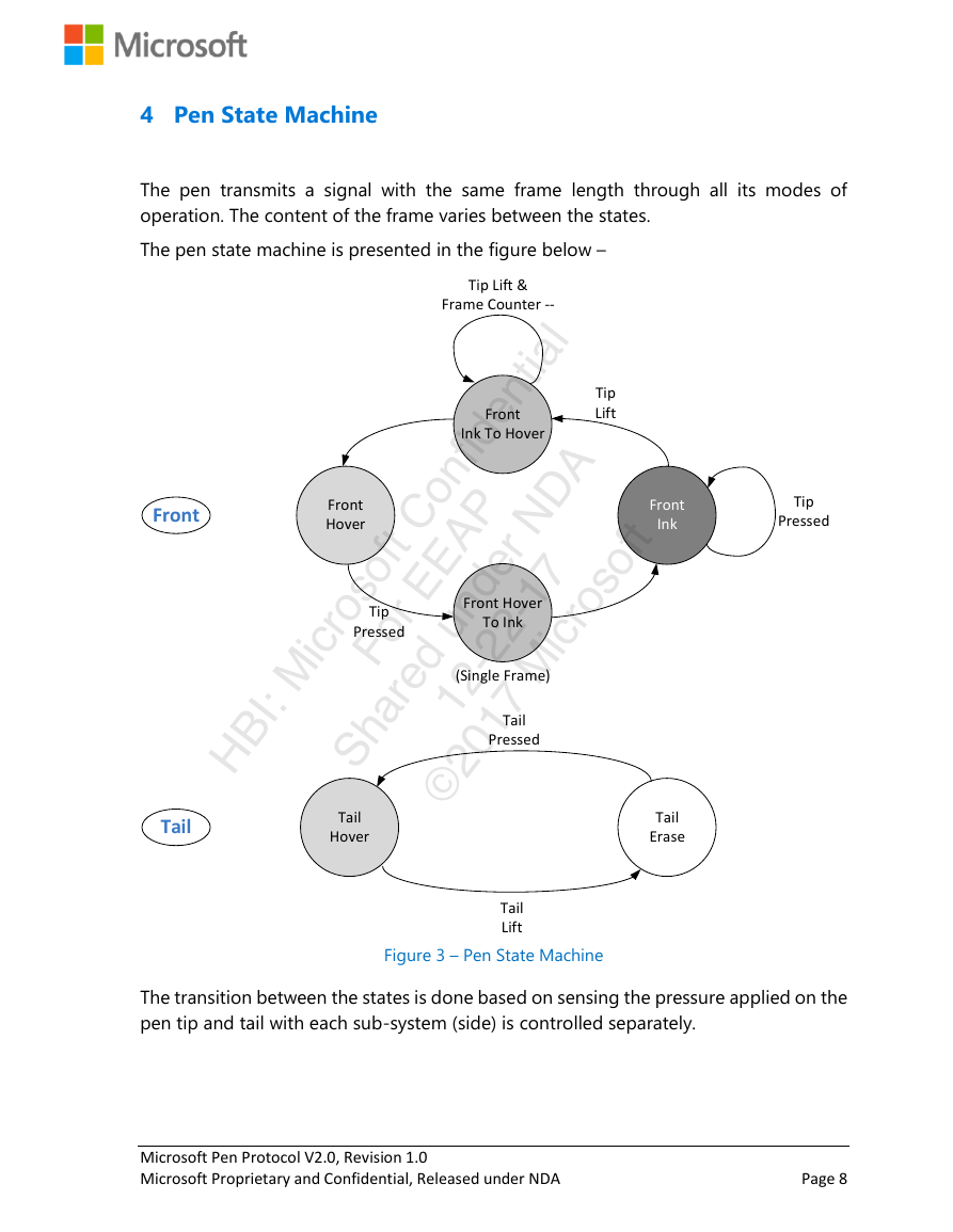
The pen transmits a signal with the same frame length through all its modes of
operation. The content of the frame varies between the states.
The pen state machine is presented in the figure below –
HBI: Microsoft Confidential
Shared under NDA
For EEAP
© 2017 Microsoft
12-22-17
Figure 3 – Pen State Machine
The transition between the states is done based on sensing the pressure applied on the
pen tip and tail with each sub-system (side) is controlled separately.
Microsoft Pen Protocol V2.0, Revision 1.0
Microsoft Proprietary and Confidential, Released under NDA
Page 8
Front HoverFront InkFront Ink To HoverFront Hover To InkTail EraseTail PressedTail LiftTip PressedTip LiftTip Pressed(Single Frame)Tip Lift &Frame Counter --TailHoverFrontTail�



 2023年江西萍乡中考道德与法治真题及答案.doc
 2012年重庆南川中考生物真题及答案.doc
 2013年江西师范大学地理学综合及文艺理论基础考研真题.doc
 2020年四川甘孜小升初语文真题及答案I卷.doc
 2020年注册岩土工程师专业基础考试真题及答案.doc
 2023-2024学年福建省厦门市九年级上学期数学月考试题及答案.doc
 2021-2022学年辽宁省沈阳市大东区九年级上学期语文期末试题及答案.doc
 2022-2023学年北京东城区初三第一学期物理期末试卷及答案.doc
 2018上半年江西教师资格初中地理学科知识与教学能力真题及答案.doc
 2012年河北国家公务员申论考试真题及答案-省级.doc
 2020-2021学年江苏省扬州市江都区邵樊片九年级上学期数学第一次质量检测试题及答案.doc
 2022下半年黑龙江教师资格证中学综合素质真题及答案.doc