多功能数字时钟设计--------02073017 王威
多功能数字钟设计
1 实验目的
熟练 VHDL 语言设计,并用 VHDL 描述出一个多功能的数字时钟
2 实验原理
数字时钟实际上是个级联的计数器,我们可以首先设计出模 60 和模 24 的计数器,
分别充当时钟的秒、分和时计数。然后加上必要的控制信号如调时、清零等和输
出如数码管显示信号、报时信号等就构成了简易的电子时钟。
3 实验内容
1)根据实验要求设计模 60 计数器
因为此计数器要作为时钟的分秒计时信号所以除了时钟 CLK 信号外还需加使
能信号 EN、清零信号 CR、分秒加减信号 bit1 和 bit2;输出信号 OC 为循环
计数标志信号可用作后级级联计数器的使能信号,QL、QH 为两位计数输出信
号。
仿真波形
仿真结果分析:由仿真波形可以看出 QL 实现了模 10 计数器的功能,而 QH
则是模 6 计数,两级级联实现了模 60 计数,60 个时钟周期实现一个大循环。
VHDL 描述:
library ieee;
use ieee.std_logic_1164.all;
use ieee.std_logic_unsigned.all;
entity bcd_m60 is
port(
CLK :in std_logic;
EN :in std_logic;
CR :in std_logic;
bit1 :in std_logic;
bit2 :in std_logic;
QL,QH :out std_logic_vector(3 downto 0);
OC :out std_logic
);
end bcd_m60;
architecture behav of bcd_m60 is
- 1 -
�
多功能数字时钟设计--------02073017 王威
signal couL,couH:std_logic_vector(3 downto 0);
begin
process(CR,CLK,bit1,bit2,couL)
begin
if CR='0' then
couL<="0000";
couH<="0000";
elsif bit1='0' then
couL<=couL+1;
elsif bit2='0' then
couL<=couL-1;
elsif clk'event and clk='1' then
if EN='1' then
if (couL=9 and couH=5)then
couL<="0000";
couH<="0000";
elsif couL=9 then
couL<="0000";
couH<=couH+1;
else
couL<=couL+1;
end if;
end if;
end if;
end process;
process(couL,couH)
begin
if(couL=9 and couH=5)then
OC<='1';
else
OC<='0';
end if;
end process;
QL<=couL;
QH<=couH;
end behav;
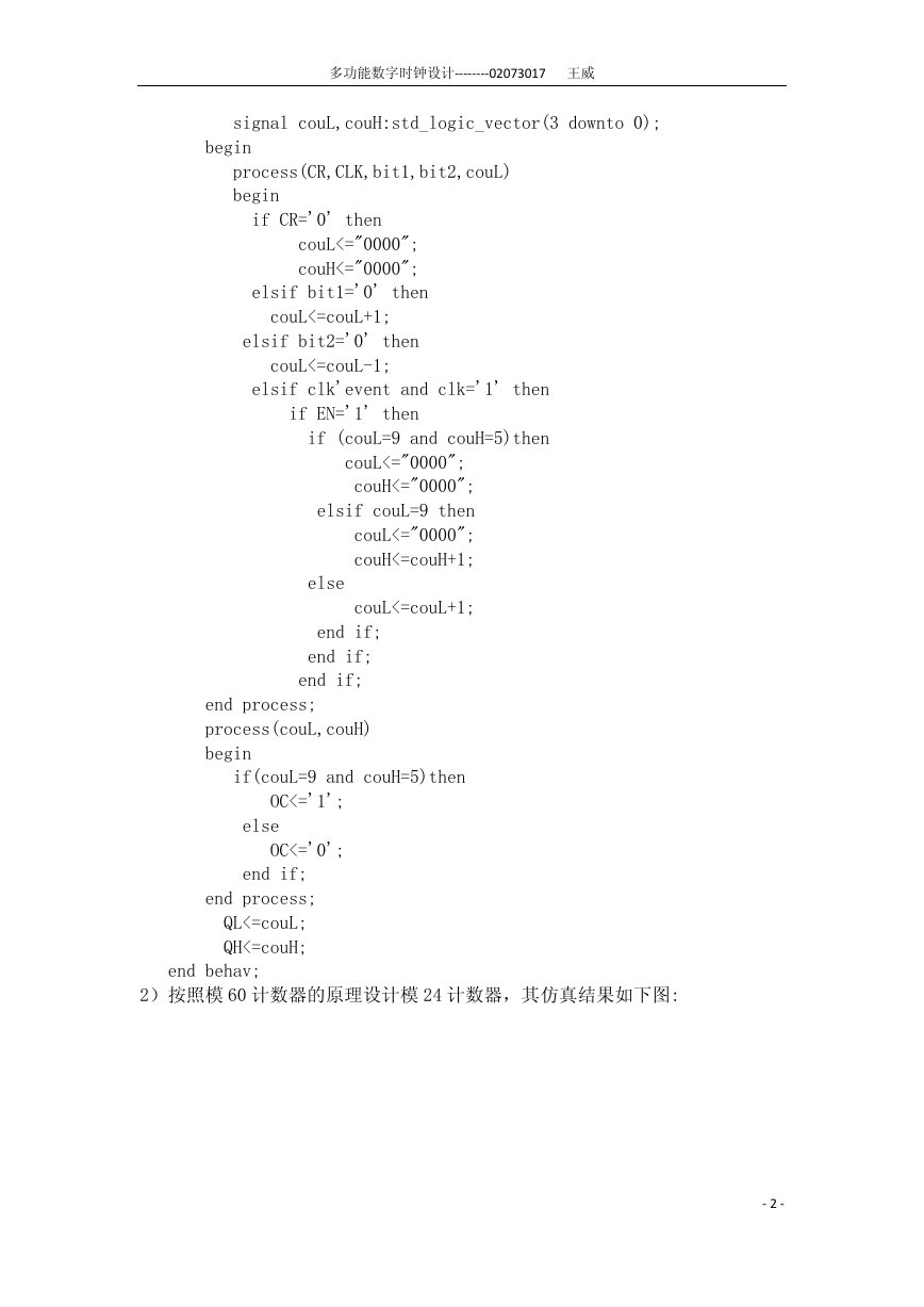
2)按照模 60 计数器的原理设计模 24 计数器,其仿真结果如下图:
- 2 -
�
多功能数字时钟设计--------02073017 王威
3)显示译码器
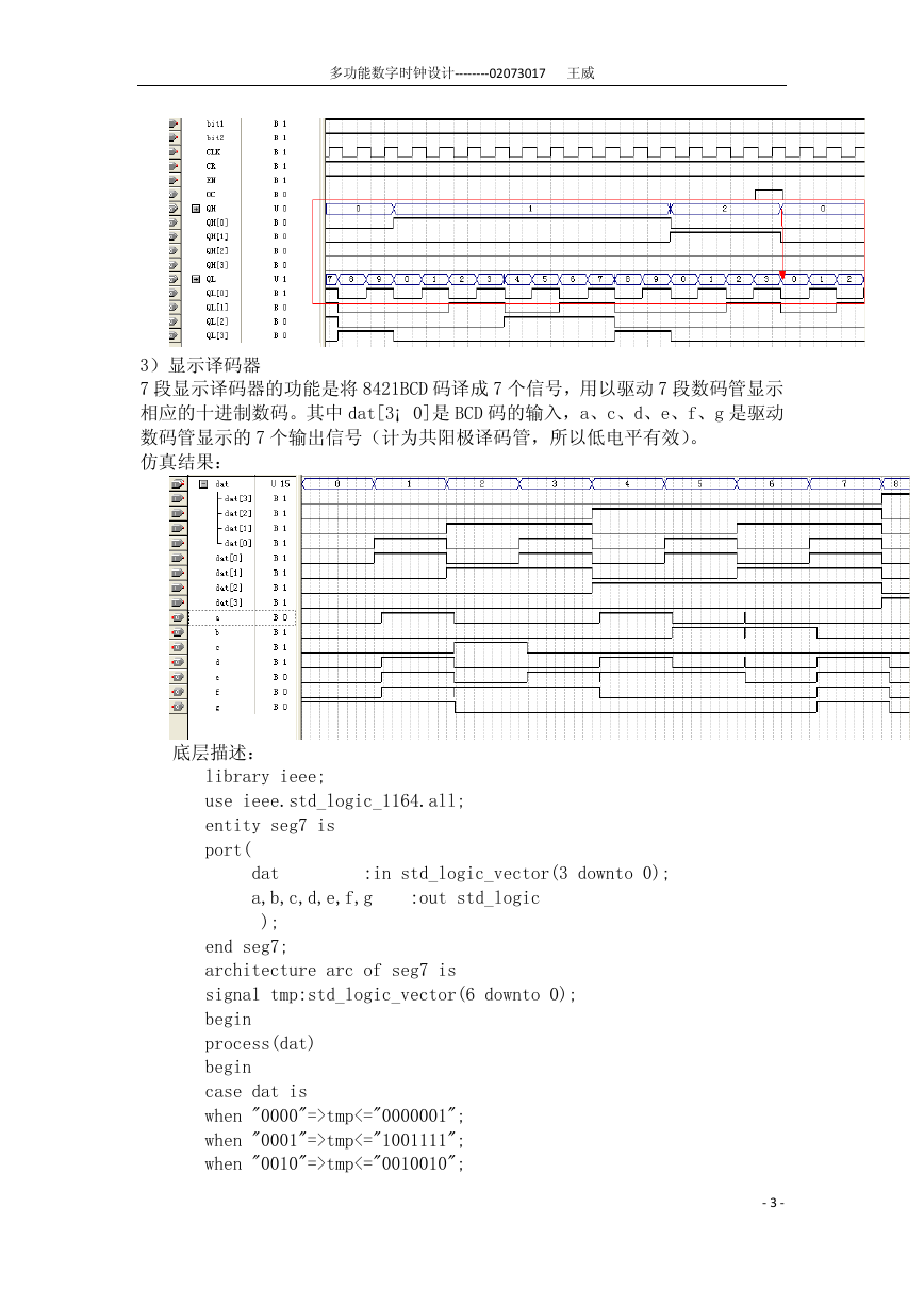
7 段显示译码器的功能是将 8421BCD 码译成 7 个信号,用以驱动 7 段数码管显示
相应的十进制数码。其中 dat[3¡ 0]是 BCD 码的输入,a、c、d、e、f、g 是驱动
数码管显示的 7 个输出信号(计为共阳极译码管,所以低电平有效)。
仿真结果:
底层描述:
library ieee;
use ieee.std_logic_1164.all;
entity seg7 is
port(
dat :in std_logic_vector(3 downto 0);
a,b,c,d,e,f,g :out std_logic
);
end seg7;
architecture arc of seg7 is
signal tmp:std_logic_vector(6 downto 0);
begin
process(dat)
begin
case dat is
when "0000"=>tmp<="0000001";
when "0001"=>tmp<="1001111";
when "0010"=>tmp<="0010010";
- 3 -
�
多功能数字时钟设计--------02073017 王威
when "0011"=>tmp<="0000110";
when "0100"=>tmp<="1001100";
when "0101"=>tmp<="0100100";
when "0110"=>tmp<="0100000";
when "0111"=>tmp<="0001111";
when "1000"=>tmp<="0000000";
when "1001"=>tmp<="0000100";
when "1010"=>tmp<="0001000";
when "1011"=>tmp<="1100000";
when "1100"=>tmp<="0110001";
when "1101"=>tmp<="1000010";
when "1110"=>tmp<="0110000";
when "1111"=>tmp<="0111000";
end case;
end process;
a<=tmp(6);
b<=tmp(5);
c<=tmp(4);
d<=tmp(3);
e<=tmp(2);
f<=tmp(1);
g<=tmp(0);
end arc;
4)整点报时器
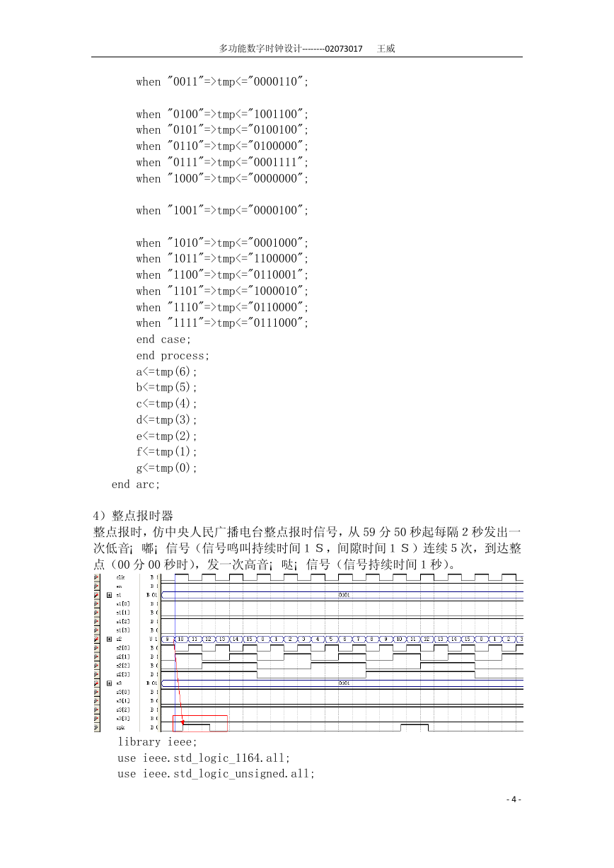
整点报时,仿中央人民广播电台整点报时信号,从 59 分 50 秒起每隔2秒发出一
次低音¡ 嘟¡ 信号(信号鸣叫持续时间1S,间隙时间1S)连续5次,到达整
点(00 分 00 秒时),发一次高音¡ 哒¡ 信号(信号持续时间1秒)。
library ieee;
use ieee.std_logic_1164.all;
use ieee.std_logic_unsigned.all;
- 4 -
�
多功能数字时钟设计--------02073017 王威
entity spk is
port(
clk: in std_logic;
s1: in std_logic_vector(3 downto 0);
s2: in std_logic_vector(3 downto 0);
s3: in std_logic_vector(3 downto 0);
en: in std_logic;
spk: out std_logic
);
end spk;
architecture arc_spk of spk is
begin
process
begin
wait until clk'event and clk='1';
if en ='0' then
spk<='0';
elsif (s1=5 and s2=9 and s3=5) then
spk<='1';
end if ;
end process;
end arc_spk;
5)调时控制器
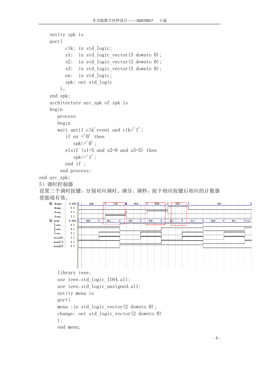
设置三个调时按键,分别对应调时、调分、调秒,按下相应按键后相应的计数器
使能端有效。
library ieee;
use ieee.std_logic_1164.all;
use ieee.std_logic_unsigned.all;
entity menu is
port(
menu :in std_logic_vector(2 downto 0);
change: out std_logic_vector(2 downto 0)
);
end menu;
- 5 -
�
多功能数字时钟设计--------02073017 王威
architecture arc_menu of menu is
begin
process(menu)
begin
case menu is
when "110"=>change<="001";
when "101"=>change<="010";
when "011"=>change<="100";
when others=>change<="000";
end case;
end process;
end arc_menu;
6)分频器
分频器设计
为了实现实时的时钟计数需要对实验板提供的 4M 时钟信号进行 4M 分频,得到
需要的 1Hz 时钟。因此分频器的输入端只有一个时钟信号 CLK,输出也只有一个
分频后的时钟 CLK-OUT。但在实际中考虑到分频系数比较大,采用了模拟十分频
的方法。
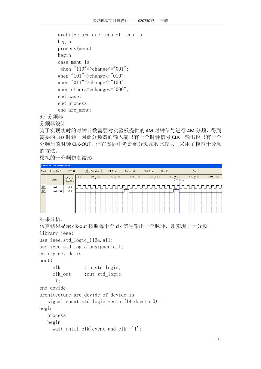
模拟的十分频仿真波形
结果分析:
仿真结果显示 clk-out 按照每十个 clk 信号输出一个脉冲,即实现了十分频。
library ieee;
use ieee.std_logic_1164.all;
use ieee.std_logic_unsigned.all;
entity devide is
port(
clk :in std_logic;
clk_out :out std_logic
);
end devide;
architecture arc_devide of devide is
signal count:std_logic_vector(14 downto 0);
begin
process
begin
wait until clk'event and clk ='1';
- 6 -
�
多功能数字时钟设计--------02073017 王威
if(count<3999999)then
count<=count+1;
clk_out<='0';
else
count<=(others=>'0');
clk_out<='1';
end if;
end process;
end architecture arc_devide;
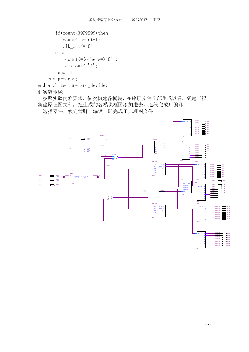
4 实验步骤
按照实验内容要求,依次构建各模块,在底层文件全部生成以后,新建工程¡
新建原理图文件,把生成的各模块框图添加进去,连线完成后编译;
选择器件,锁定管脚,编译,即完成了原理图文件。
clk
add
min
INPUT
VCC
INPUT
VCC
INPUT
VCC
dev ide
clk clk_out
inst12
change2
inst16
OR2
VCC
menu2
menu1
menu0
INPUT
VCC
INPUT
VCC
INPUT
VCC
menu
menu[2..0]
menu[2..0]
change[2..0]
change[ 2..0]
inst11
change1
inst17
OR2
QL[3..0]
QH [3..0]
OC
QL[3..0]
QH [3..0]
OC
count 24
C LK
EN
C R
bit1
bit2
inst10
bcd_m60
C LK
EN
C R
bit1
bit2
inst2
spk_en
INPUT
VCC
QL[3..0]
QH [3..0]
OC
bcd_m60
C LK
EN
C R
bit1
bit2
inst
seg7
dat[3..0]
inst4
seg7
dat [3..0]
inst3
a
b
c
d
e
f
g
a
b
c
d
e
f
g
OUTPUT
OUTPUT
OUTPUT
OUTPUT
OUTPUT
OUTPUT
OUTPUT
OUTPUT
OUTPUT
OUTPUT
OUTPUT
OUTPUT
OUTPUT
OUTPUT
seg7
H 8
H 9
H 10
H 11
H 12
H 13
H 14
H 1
H 2
H 3
H 4
H 5
H 6
H 7
spk
spk
clk
s1[3..0]
s2[3..0]
s3[3..0]
en
inst1
dat[3..0]
inst6
seg7
dat[3..0]
inst5
seg7
dat[3..0]
inst8
seg7
dat[3..0]
inst7
a
b
c
d
e
f
g
a
b
c
d
e
f
g
a
b
c
d
e
f
g
a
b
c
d
e
f
g
OUTPUT
OUTPUT
OUTPUT
OUTPUT
OUTPUT
OUTPUT
OUTPUT
OUTPUT
OUTPUT
OUTPUT
OUTPUT
OUTPUT
OUTPUT
OUTPUT
OUTPUT
H22
H23
H24
H25
H26
H27
H28
spk
H15
H16
H17
H18
H19
H20
H21
OU TPUT
OU TPUT
OU TPUT
OU TPUT
OU TPUT
OU TPUT
OU TPUT
OU TPUT
OU TPUT
OU TPUT
OU TPUT
OU TPUT
OU TPUT
OU TPUT
H36
H37
H38
H39
H40
H41
H42
H29
H30
H31
H32
H33
H34
H35
- 7 -
�



 2023年江西萍乡中考道德与法治真题及答案.doc
 2012年重庆南川中考生物真题及答案.doc
 2013年江西师范大学地理学综合及文艺理论基础考研真题.doc
 2020年四川甘孜小升初语文真题及答案I卷.doc
 2020年注册岩土工程师专业基础考试真题及答案.doc
 2023-2024学年福建省厦门市九年级上学期数学月考试题及答案.doc
 2021-2022学年辽宁省沈阳市大东区九年级上学期语文期末试题及答案.doc
 2022-2023学年北京东城区初三第一学期物理期末试卷及答案.doc
 2018上半年江西教师资格初中地理学科知识与教学能力真题及答案.doc
 2012年河北国家公务员申论考试真题及答案-省级.doc
 2020-2021学年江苏省扬州市江都区邵樊片九年级上学期数学第一次质量检测试题及答案.doc
 2022下半年黑龙江教师资格证中学综合素质真题及答案.doc