沈阳理工大学
课
题
院
程
目
系
专业班级
学生姓名
学生学号
指导教师
EDA 设计
洗衣机控制器设计
装备工程学院
探测制导与控制技术
杜继石
0811020219
钱博
2010 年 12 月 21 日
�
主要内容:
设计一个洗衣机控制器,要求洗衣机有正转、反转、暂停三种状态。设定洗衣机的工作时间,要洗
衣机在工作时间内完成:定时启动正转20秒暂停10秒反转20秒暂停10秒定时未到回到“正转20
秒暂停10秒……”,定时到则停止,同时发出提示音。
基本要求:
1、设计一个电子定时器,控制洗衣机作如下运转:定时启动正转20秒暂停10秒反转20秒暂
停10秒定时未到回到“正转20秒暂停10秒……”,定时到则停止;
2、若定时到,则停机发出音响信号;
3、用两个数码管显示洗涤的预置时间(分钟数),按倒计时方式对洗涤过程作计时显示,直到时间到
停机;洗涤过程由“开始”信号开始;
4、三只LED灯表示“正转”、“反转”、“暂停”三个状态。
一、总体设计思想
1、基本原理
洗衣机控制器的设计主要是定时器的设计。由一片 FPGA 和外围电路构成了
电器控制部分。FPGA 接收键盘的控制命令,控制洗衣机的进水、排水、水位和
洗衣机的工作状态、并控制显示工作状态以及设定直流电机速度、正反转控制、
制动控制、起停控制和运动状态控制。对芯片的编程采用模块化的 VHDL (硬件
描述语言)进行设计,设计分为三层实现,顶层实现整个芯片的功能。顶层和中
间层多数是由 VHDL 的元件例化语句实现。中间层由无刷直流电机控制、运行模
式选择、洗涤模式选择、定时器、显示控制、键盘扫描、水位控制以及对直流
电机控制板进行速度设定、正反转控制、启停控制等模块组成,它们分别调用
底层模块。
�
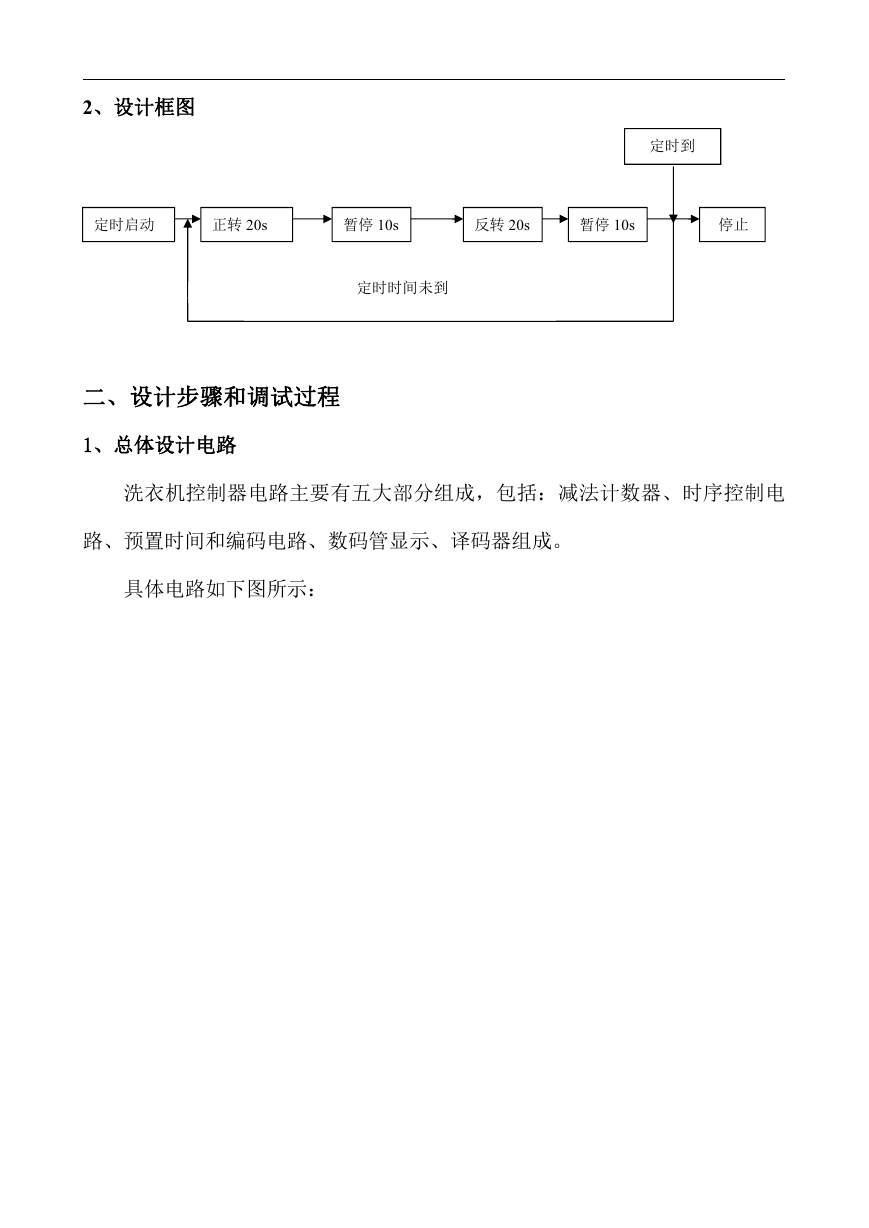
2、设计框图
定时到
定时启动
正转 20s
暂停 10s
反转 20s
暂停 10s
停止
定时时间未到
二、设计步骤和调试过程
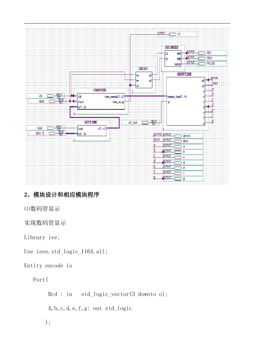
1、总体设计电路
洗衣机控制器电路主要有五大部分组成,包括:减法计数器、时序控制电
路、预置时间和编码电路、数码管显示、译码器组成。
具体电路如下图所示:
�
2、模块设计和相应模块程序
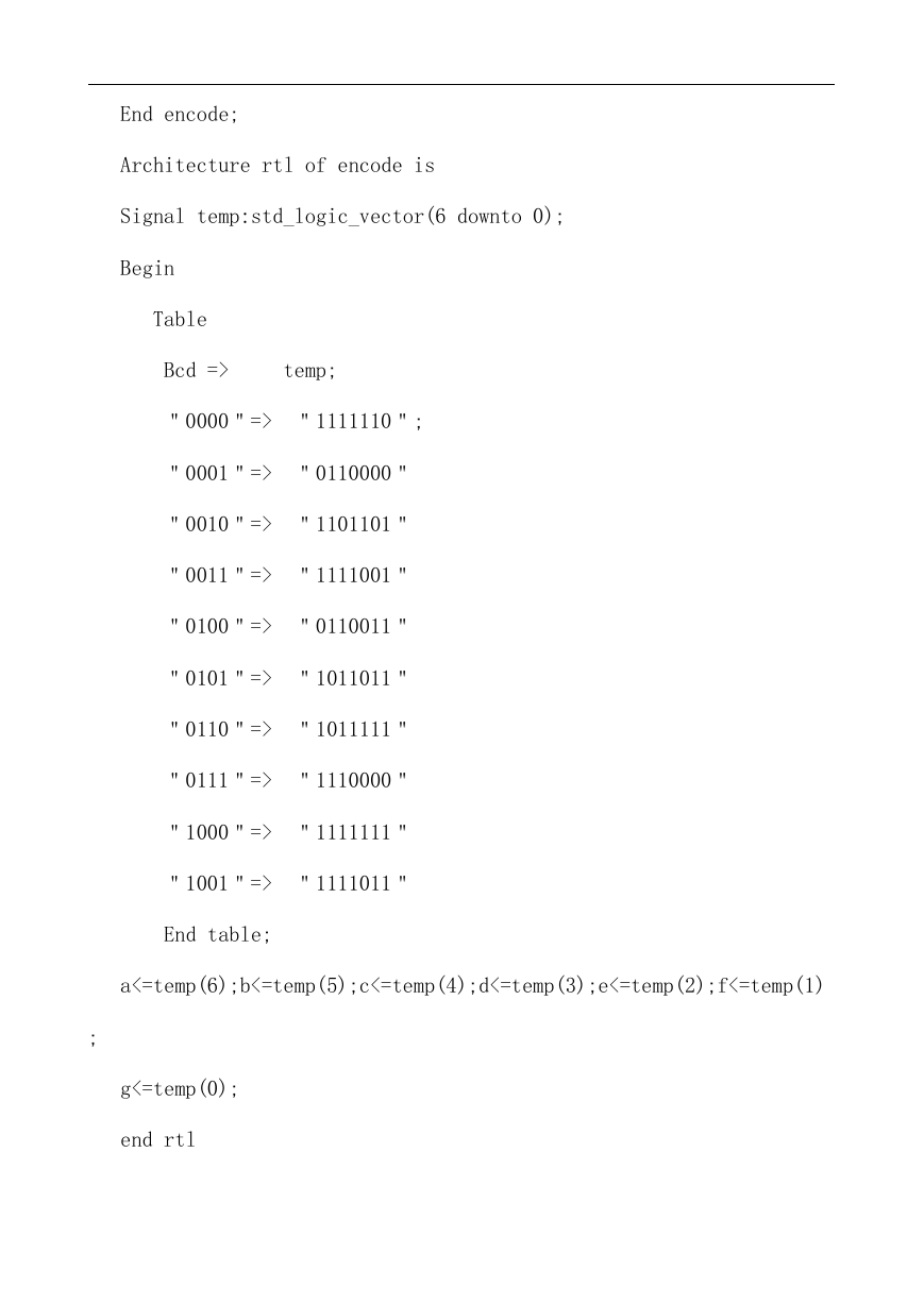
⑴数码管显示
实现数码管显示
Library iee;
Use ieee.std_logic_1164.all;
Entity encode is
Port(
Bcd : in
std_logic_vector(3 downto o);
A,b,c,d,e,f,g: out std_logic
);
�
End encode;
Architecture rtl of encode is
Signal temp:std_logic_vector(6 downto 0);
Begin
Table
Bcd =>
temp;
"0000"=> "1111110";
"0001"=> "0110000"
"0010"=> "1101101"
"0011"=> "1111001"
"0100"=> "0110011"
"0101"=> "1011011"
"0110"=> "1011111"
"0111"=> "1110000"
"1000"=> "1111111"
"1001"=> "1111011"
End table;
a<=temp(6);b<=temp(5);c<=temp(4);d<=temp(3);e<=temp(2);f<=temp(1)
;
g<=temp(0);
end rtl
�
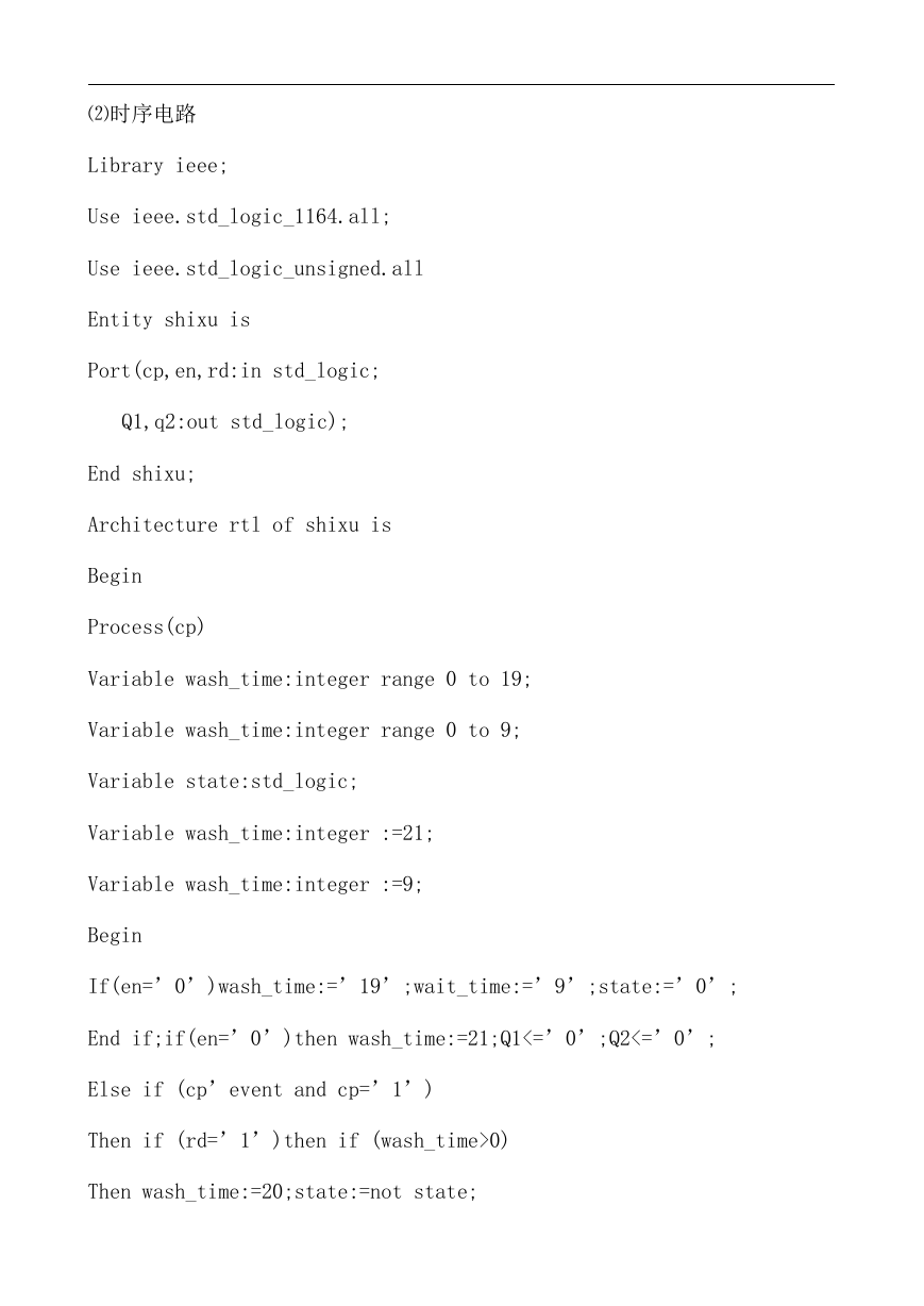
⑵时序电路
Library ieee;
Use ieee.std_logic_1164.all;
Use ieee.std_logic_unsigned.all
Entity shixu is
Port(cp,en,rd:in std_logic;
Q1,q2:out std_logic);
End shixu;
Architecture rtl of shixu is
Begin
Process(cp)
Variable wash_time:integer range 0 to 19;
Variable wash_time:integer range 0 to 9;
Variable state:std_logic;
Variable wash_time:integer :=21;
Variable wash_time:integer :=9;
Begin
If(en=’0’)wash_time:=’19’;wait_time:=’9’;state:=’0’;
End if;if(en=’0’)then wash_time:=21;Q1<=’0’;Q2<=’0’;
Else if (cp’event and cp=’1’)
Then if (rd=’1’)then if (wash_time>0)
Then wash_time:=20;state:=not state;
�
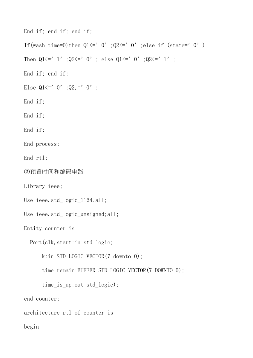
End if; end if; end if;
If(wash_time=0)then Q1<=’0’;Q2<=’0’;else if (state=’0’)
Then Q1<=’1’;Q2<=’0’; else Q1<=’0’;Q2<=’1’;
End if; end if;
Else Q1<=’0’;Q2,=’0’;
End if;
End if;
End if;
End process;
End rtl;
⑶预置时间和编码电路
Library ieee;
Use ieee.std_logic_1164.all;
Use ieee.std_logic_unsigned;all;
Entity counter is
Port(clk,start:in std_logic;
k:in STD_LOGIC_VECTOR(7 downto 0);
time_remain:BUFFER STD_LOGIC_VECTOR(7 DOWNTO 0);
time_is_up:out std_logic);
end counter;
architecture rtl of counter is
begin
�
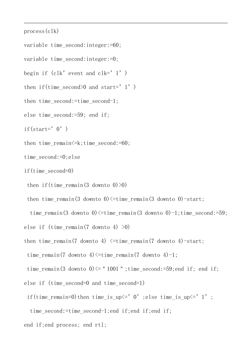
process(clk)
variable time_second:integer:=60;
variable time_second:integer:=0;
begin if (clk’event and clk=’1’)
then if(time_second>0 and start=’1’)
then time_second:=time_second-1;
else time_second:=59; end if;
if(start=’0’)
then time_remain<=k;time_second:=60;
time_second:=0;else
if(time_second=0)
then if(time_remain(3 downto 0)>0)
then time_remain(3 downto 0)<=time_remain(3 downto 0)-start;
time_remain(3 downto 0)<=time_remain(3 downto 0)-1;time_second:=59;
else if (time_remain(7 downto 4) >0)
then time_remain(7 downto 4) <=time_remain(7 downto 4)-start;
time_remain(7 downto 4)<=time_remain(7 downto 4)-1;
time_remain(3 downto 0)<="1001";time_second:=59;end if; end if;
else if (time_second=0 and time_second=1)
if(time_remain=0)then time_is_up<=’0’;else time_is_up<=’1’;
time_second:=time_second-1;end if;end if;end if;
end if;end process; end rtl;
�


 2023年江西萍乡中考道德与法治真题及答案.doc
 2012年重庆南川中考生物真题及答案.doc
 2013年江西师范大学地理学综合及文艺理论基础考研真题.doc
 2020年四川甘孜小升初语文真题及答案I卷.doc
 2020年注册岩土工程师专业基础考试真题及答案.doc
 2023-2024学年福建省厦门市九年级上学期数学月考试题及答案.doc
 2021-2022学年辽宁省沈阳市大东区九年级上学期语文期末试题及答案.doc
 2022-2023学年北京东城区初三第一学期物理期末试卷及答案.doc
 2018上半年江西教师资格初中地理学科知识与教学能力真题及答案.doc
 2012年河北国家公务员申论考试真题及答案-省级.doc
 2020-2021学年江苏省扬州市江都区邵樊片九年级上学期数学第一次质量检测试题及答案.doc
 2022下半年黑龙江教师资格证中学综合素质真题及答案.doc