logo资料库

SICK_仪器通信协议.doc

第1页 / 共99页
第2页 / 共99页
第3页 / 共99页
第4页 / 共99页
第5页 / 共99页
第6页 / 共99页
第7页 / 共99页
第8页 / 共99页
资料共99页,剩余部分请下载后查看
1.1LMS 2XX
1.2LMI 400
2Definition of interface between LMS or LMI and hos
2.1Electrical interface:
2.2Transfer and data format:
2.3LMS and LMI telegram structure:
2.3.1Structure of the LMS xx1 to xx4 and xx6 status byt
2.3.2Structure of the LMI status byte
2.4Formation of the CRC16 checksum
3Example of communication procedure for receiving m
3.1Receipt of an LMS scan's complete measured value s
3.2Receipt of averaged measured values
4Description of available telegrams
4.1Data direction: Host computer -> LMS / LMI
4.1.1Start sequence for download to the flash eprom (LM
4.1.2Download data for the flash eprom (LMS-2xx-xxx06)
4.1.3Reserved for internal use (0DH)
4.1.4Reserved for internal use (0EH)
4.1.5Reserved for internal use (0FH)
4.1.6Initialisation and reset (LMS and LMI) (10H)
4.1.7Select or change operating mode (LMS and LMI) (20H
4.1.8Request for measured values (LMS and LMI) (30H)
4.1.9Request for sensor status (LMS and LMI) (31H)
4.1.10Request for error telegram (LMS and LMI) (32H)
4.1.11Request for test in diagnostic mode (LMS and LMI)
4.1.12Request for a memory dump (LMS-2xx-xxx06 and LMI)
4.1.13Request for a memory dump (LMS-2xx-xxx01 - 05) (34
4.1.14Request for averaged measured values (LMS and LMI)
4.1.15Request for partitioned measured values (LMS and L
4.1.16Request for LMI configuration (LMI) (38H)
4.1.17Request for evaluation case definitions (LMI) (39H
4.1.18Request for LMS type (LMS) (3AH)
4.1.19Change of LMS variant (LMS-2xx-xxx06)(3BH)
4.1.20Request for reference target values (LMS-2xx-xxx06
4.1.21Request for correction values (LMS-2xx-xxx06) (3DH
4.1.22Request for averaged partitioned measured values (
4.1.23Configuration of fields A, B or C (LMS-2xx-xxx06 a
4.1.24Change active field group (LMS- 2xx-xxx06) (41H)
4.1.25Change password (only in installation or calibrati
4.1.26Request for configured fields (LMS-2xx-xxx06 and L
4.1.27Teach mode for field configuration (LMS-2xx-xxx06
4.1.28Configuration of a dynamic rectangular field (only
4.1.29Configuration of a dynamic segmented field (only i
4.1.30Activation of a dynamic field using index or simul
4.1.31Activation / deactivation of outputs (LMS and LMI)
4.1.32Read the state of the inputs (LMI) (4EH)
4.1.33Define or simulate input information to change an
4.1.34Carry out calibration (only in calibration mode )
4.1.35Define permanent baud rate or sensor type (only in
4.1.36Define LMS or LMI address (only in installation or
4.1.37Activate / deactivate laser transmitter (LMS) (68H
4.1.38Definition of LMI configuration
4.1.39Definition of an evaluation case
4.1.40Read LMS configuration (LMS-2xx-xxx06) (74H)
4.1.41Request for measured values in Cartesian co-ordina
4.1.42Define LMS-2xx-xxx06 configuration
4.1.43Definition of correction parameters
4.2Data direction LMS / LMI -> Host computer
4.2.1Reserved for internal use (8DH)
4.2.2Reserved for internal use (8EH)
4.2.3Reserved for internal use (8FH)
4.2.4Message after Power On (response from LMS and LMI)
4.2.5Confirmation of software reset telegram (response
4.2.6Not acknowledge (response from LMS and LMI) (92H)
4.2.7Response to change of operating mode (A0H)
4.2.8Response to request for measured values (response
4.2.9LMS sensor status (LMS-2xx-xxx01 to 04) (B1H)
4.2.10LMS sensor status (LMS-2xx-xxx06) (B1H)
4.2.11LMI status (B1H)
4.2.12Error message / test message (response from LMS an
4.2.13Memory dump on request (only in diagnostic mode) (
4.2.14Memory dump on request (only in diagnostic mode) (
4.2.15Send averaged measured values (response from LMS a
4.2.16Send partitioned measured values (response from LM
4.2.17LMI configuration data (B8H)
4.2.18Definition of data for an evaluation case (LMI) (B
4.2.19Information on LMS type (LMS) (BAH)
4.2.20Response to change of LMS variant (LMS-2xx-xxx06)
4.2.21Reference target values (LMS-2xx-xxx06) (BCH)
4.2.22Correction values (LMS-2xx-xxx06) (BDH)
4.2.23Send averaged partitioned measured values (LMS and
4.2.24Response to field configuration (LMS-2xx-xxx06 and
4.2.25Change active field group (LMS- 2xx-xxx06) (C1H)
4.2.26Confirmation of new password (LMS and LMI) (C2H)
4.2.27Configuration data for programmed fields (LMS-2xx-
4.2.28Response in teach mode (LMI and LMS-2xx-xxx06) (C6
4.2.29Response to configuration of a dynamic rectangular
4.2.30Response to configuration of a dynamic segmented f
4.2.31Response to switching of dynamic field using index
4.2.32Response to activation / deactivation of outputs (
4.2.33Current input data (LMI) (CEH)
4.2.34Response to definition of input information for an
4.2.35Response to calibration (response from LMS and LMI
4.2.36Response to permanent baud rate definition (respon
4.2.37Response to definition of LMS / LMI addr
4.2.38Response to activate / deactivate laser transmitte
4.2.39Response to LMI configuration
4.2.40Response to definition of an evaluation case
4.2.41Current LMS configuration (response from LMS-2xx-x
4.2.42Response to request for measured values in Cartesi
4.2.43Response to definition of LMS-2xx-xxx06 configurat
4.2.44Response to definition of correction parameters
5OVERVIEW OF AVAILABLE TELEGRAMS
5.1Data direction: Host computer -> Sensor
5.2Data direction: Sensor -> Host computer
6LIST OF ERROR NUMBERS FOR LMS AND LMI
6.1LMS (LMS-2xx-xxx01 to 4) error list
6.2LMS (LMS-2xx-xxx06) error list
6.3LMI error list
7ABBREVIATIONS AND NOTES
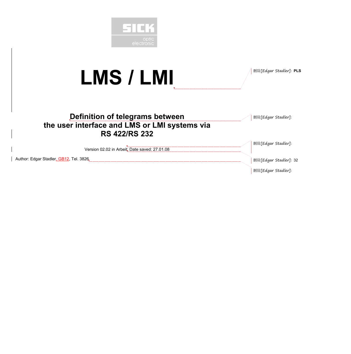
LMS / LMI Definition of telegrams between the user interface and LMS or LMI systems via RS 422/RS 232 Author: Edgar Stadler, GB12, Tel. 3826 Version 02.02 in Arbeit; Date saved: 27.01.08 删除[Edgar Stadler]: PLS 删除[Edgar Stadler]: 删除[Edgar Stadler]: 删除[Edgar Stadler]: 32 删除[Edgar Stadler]:
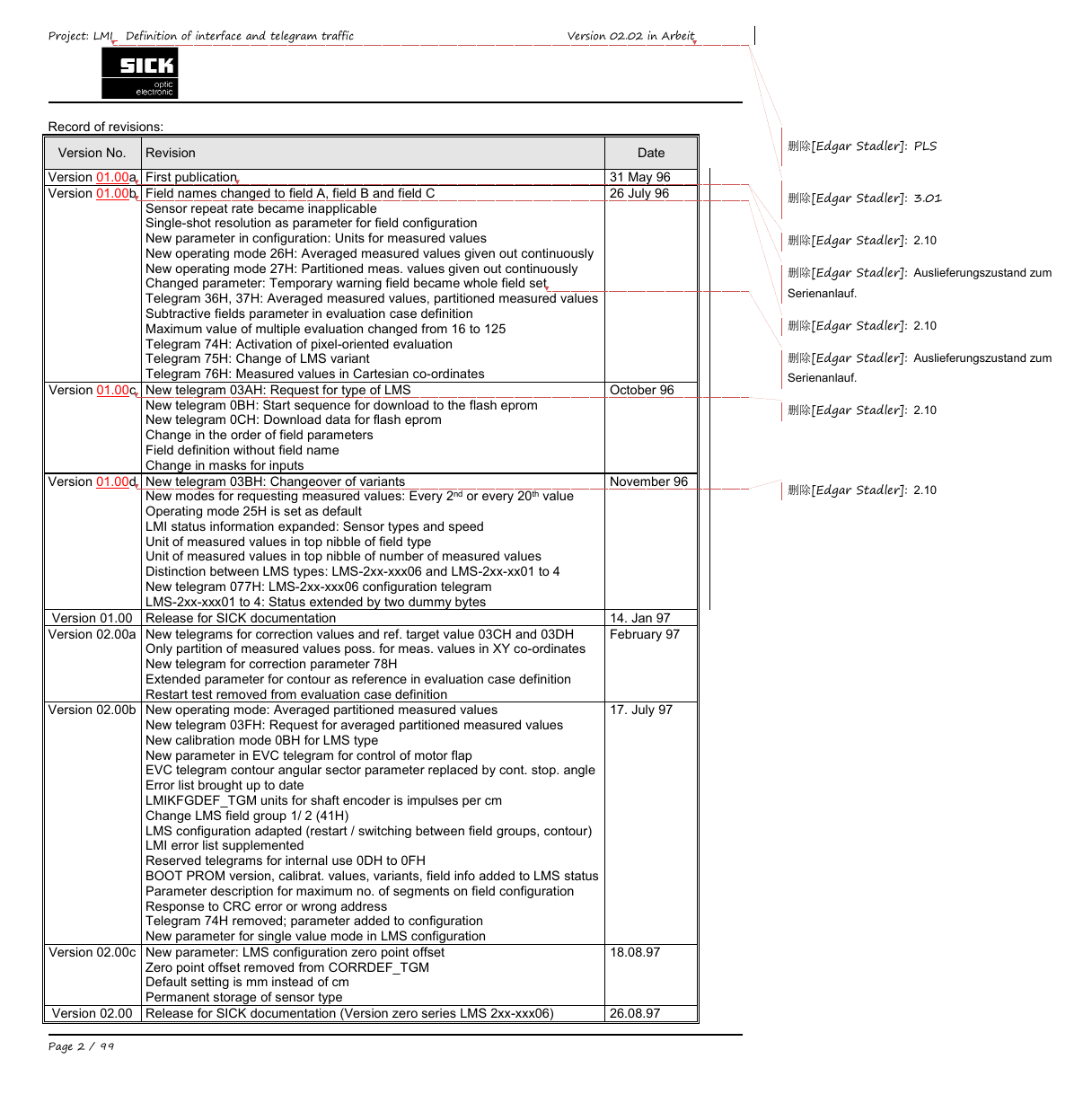
Project: LMI Definition of interface and telegram traffic Version 02.02 in Arbeit Record of revisions: Version No. Revision Version 01.00a First publication Version 01.00b Field names changed to field A, field B and field C Sensor repeat rate became inapplicable Single-shot resolution as parameter for field configuration New parameter in configuration: Units for measured values New operating mode 26H: Averaged measured values given out continuously New operating mode 27H: Partitioned meas. values given out continuously Changed parameter: Temporary warning field became whole field set Telegram 36H, 37H: Averaged measured values, partitioned measured values Subtractive fields parameter in evaluation case definition Maximum value of multiple evaluation changed from 16 to 125 Telegram 74H: Activation of pixel-oriented evaluation Telegram 75H: Change of LMS variant Telegram 76H: Measured values in Cartesian co-ordinates Version 01.00c New telegram 03AH: Request for type of LMS New telegram 0BH: Start sequence for download to the flash eprom New telegram 0CH: Download data for flash eprom Change in the order of field parameters Field definition without field name Change in masks for inputs Version 01.00d New telegram 03BH: Changeover of variants New modes for requesting measured values: Every 2nd or every 20th value Operating mode 25H is set as default LMI status information expanded: Sensor types and speed Unit of measured values in top nibble of field type Unit of measured values in top nibble of number of measured values Distinction between LMS types: LMS-2xx-xxx06 and LMS-2xx-xx01 to 4 New telegram 077H: LMS-2xx-xxx06 configuration telegram LMS-2xx-xxx01 to 4: Status extended by two dummy bytes Version 01.00 Release for SICK documentation Version 02.00a New telegrams for correction values and ref. target value 03CH and 03DH Only partition of measured values poss. for meas. values in XY co-ordinates New telegram for correction parameter 78H Extended parameter for contour as reference in evaluation case definition Restart test removed from evaluation case definition Version 02.00b New operating mode: Averaged partitioned measured values New telegram 03FH: Request for averaged partitioned measured values New calibration mode 0BH for LMS type New parameter in EVC telegram for control of motor flap EVC telegram contour angular sector parameter replaced by cont. stop. angle Error list brought up to date LMIKFGDEF_TGM units for shaft encoder is impulses per cm Change LMS field group 1/ 2 (41H) LMS configuration adapted (restart / switching between field groups, contour) LMI error list supplemented Reserved telegrams for internal use 0DH to 0FH BOOT PROM version, calibrat. values, variants, field info added to LMS status Parameter description for maximum no. of segments on field configuration Response to CRC error or wrong address Telegram 74H removed; parameter added to configuration New parameter for single value mode in LMS configuration Version 02.00c New parameter: LMS configuration zero point offset Zero point offset removed from CORRDEF_TGM Default setting is mm instead of cm Permanent storage of sensor type Version 02.00 Release for SICK documentation (Version zero series LMS 2xx-xxx06) Page 2 / 99 Date 31 May 96 26 July 96 October 96 删除[Edgar Stadler]: PLS 删除[Edgar Stadler]: 3.01 删除[Edgar Stadler]: 2.10 删除[Edgar Stadler]: Serienanlauf. Auslieferungszustand zum 删除[Edgar Stadler]: 2.10 删除[Edgar Stadler]: Serienanlauf. Auslieferungszustand zum 删除[Edgar Stadler]: 2.10 November 96 删除[Edgar Stadler]: 2.10 14. Jan 97 February 97 17. July 97 18.08.97 26.08.97
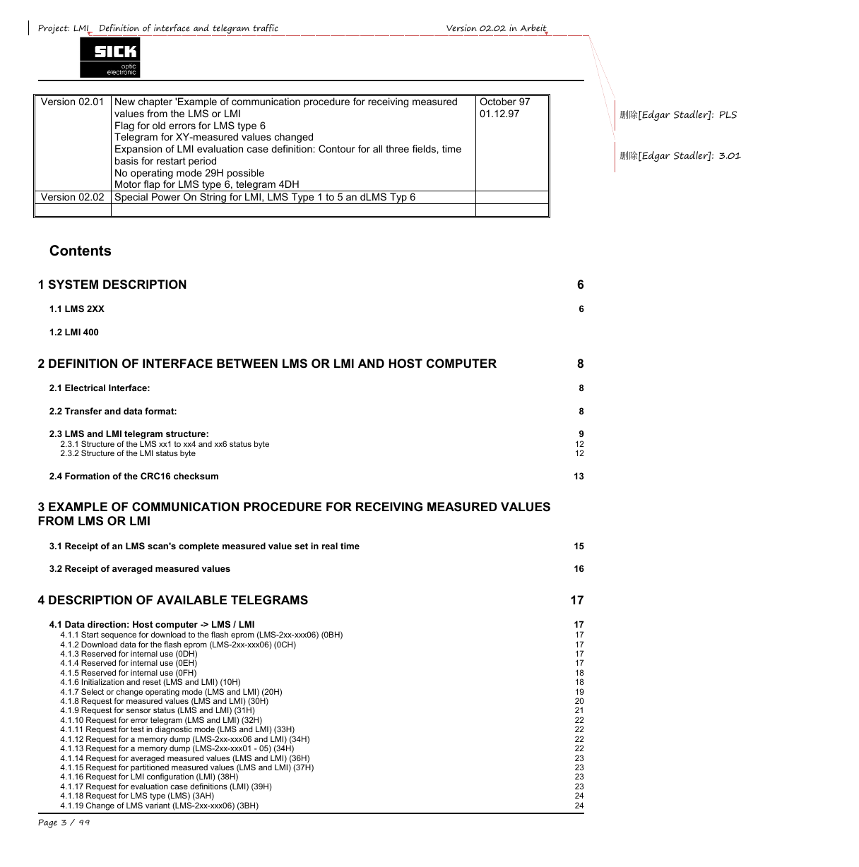
Project: LMI Definition of interface and telegram traffic Version 02.02 in Arbeit Version 02.01 New chapter 'Example of communication procedure for receiving measured values from the LMS or LMI Flag for old errors for LMS type 6 Telegram for XY-measured values changed Expansion of LMI evaluation case definition: Contour for all three fields, time basis for restart period No operating mode 29H possible Motor flap for LMS type 6, telegram 4DH Version 02.02 Special Power On String for LMI, LMS Type 1 to 5 an dLMS Typ 6 October 97 01.12.97 删除[Edgar Stadler]: PLS 删除[Edgar Stadler]: 3.01 Contents 1 SYSTEM DESCRIPTION 1.1 LMS 2XX 1.2 LMI 400 2 DEFINITION OF INTERFACE BETWEEN LMS OR LMI AND HOST COMPUTER 2.1 Electrical Interface: 2.2 Transfer and data format: 2.3 LMS and LMI telegram structure: 2.3.1 Structure of the LMS xx1 to xx4 and xx6 status byte 2.3.2 Structure of the LMI status byte 2.4 Formation of the CRC16 checksum 3 EXAMPLE OF COMMUNICATION PROCEDURE FOR RECEIVING MEASURED VALUES FROM LMS OR LMI 3.1 Receipt of an LMS scan's complete measured value set in real time 3.2 Receipt of averaged measured values 4 DESCRIPTION OF AVAILABLE TELEGRAMS 4.1 Data direction: Host computer -> LMS / LMI 4.1.1 Start sequence for download to the flash eprom (LMS-2xx-xxx06) (0BH) 4.1.2 Download data for the flash eprom (LMS-2xx-xxx06) (0CH) 4.1.3 Reserved for internal use (0DH) 4.1.4 Reserved for internal use (0EH) 4.1.5 Reserved for internal use (0FH) 4.1.6 Initialization and reset (LMS and LMI) (10H) 4.1.7 Select or change operating mode (LMS and LMI) (20H) 4.1.8 Request for measured values (LMS and LMI) (30H) 4.1.9 Request for sensor status (LMS and LMI) (31H) 4.1.10 Request for error telegram (LMS and LMI) (32H) 4.1.11 Request for test in diagnostic mode (LMS and LMI) (33H) 4.1.12 Request for a memory dump (LMS-2xx-xxx06 and LMI) (34H) 4.1.13 Request for a memory dump (LMS-2xx-xxx01 - 05) (34H) 4.1.14 Request for averaged measured values (LMS and LMI) (36H) 4.1.15 Request for partitioned measured values (LMS and LMI) (37H) 4.1.16 Request for LMI configuration (LMI) (38H) 4.1.17 Request for evaluation case definitions (LMI) (39H) 4.1.18 Request for LMS type (LMS) (3AH) 4.1.19 Change of LMS variant (LMS-2xx-xxx06) (3BH) Page 3 / 99 6 6 8 8 8 9 12 12 13 15 16 17 17 17 17 17 17 18 18 19 20 21 22 22 22 22 23 23 23 23 24 24
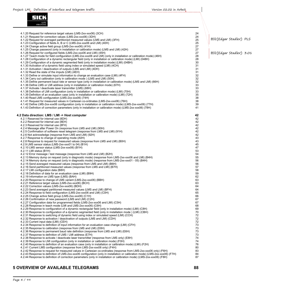
删除[Edgar Stadler]: PLS 删除[Edgar Stadler]: 3.01 Project: LMI Definition of interface and telegram traffic Version 02.02 in Arbeit 4.1.20 Request for reference target values (LMS-2xx-xxx06) (3CH) 4.1.21 Request for correction values (LMS-2xx-xxx06) (3DH) 4.1.22 Request for averaged partitioned measured values (LMS and LMI) (3FH) 4.1.23 Configuration of fields A, B or C (LMS-2xx-xxx06 and LMI) (40H) 4.1.24 Change active field group (LMS-2xx-xxx06) (41H) 4.1.25 Change password (only in installation or calibration mode) (LMS and LMI) (42H) 4.1.26 Request for configured fields (LMS-2xx-xxx06 and LMI) (45H) 4.1.27 Teach mode for field configuration (LMS-2xx-xxx06 and LMI) (only in installation or calibration mode) (46H) 4.1.28 Configuration of a dynamic rectangular field (only in installation or calibration mode) (LMI) (048H) 4.1.29 Configuration of a dynamic segmented field (only in installation mode) (LMI) (04BH) 4.1.30 Activation of a dynamic field using index or simulated speed (LMI) (4CH) 4.1.31 Activation / deactivation of outputs (LMS and LMI) (4DH) 4.1.32 Read the state of the imputs (LMI) (4EH) 4.1.33 Define or simulate input information to change an evaluation case (LMI) (4FH) 4.1.34 Carry out calibration (only in calibration mode ) (LMS and LMI) (50H) 4.1.35 Define permanent baud rate or sensor type (only in installation or calibration mode) (LMS and LMI) (66H) 4.1.36 Define LMS or LMI address (only in installation or calibration mode) (67H) 4.1.37 Activate / deactivate laser transmitter (LMS) (68H) 4.1.38 Definition of LMI configuration (only in installation or calibration mode) (LMI) (70H) 4.1.39 Definition of an evaluation case (only in installation or calibration mode) (LMI) (72H) 4.1.40 Read LMS configuration (LMS-2xx-xxx06) (74H) 4.1.41 Request for measured values in Cartesian co-ordinates (LMS-2xx-xxx06) (76H) 4.1.42 Define LMS-2xx-xxx06 configuration (only in installation or calibration mode) (LMS-2xx-xxx06) (77H) 4.1.43 Definition of correction parameters (only in installation or calibration mode) (LMS-2xx-xxx06) (78H) 4.2 Data direction: LMS / LMI -> Host computer 4.2.1 Reserved for internal use (8DH) 4.2.2 Reserved for internal use (8EH) 4.2.3 Reserved for internal use (8FH) 4.2.4 Message after Power On (response from LMS and LMI) (90H) 4.2.5 Confirmation of software reset telegram (response from LMS and LMI) (91H) 4.2.6 Not acknowledge (response from LMS and LMI) (92H) 4.2.7 Response to change of operating mode (A0H) 4.2.8 Response to request for measured values (response from LMS and LMI) (B0H) 4.2.9 LMS sensor status (LMS-2xx-xxx01 to 04) (B1H) 4.2.10 LMS sensor status (LMS-2xx-xxx06) (B1H) 4.2.11 LMI status (B1H) 4.2.12 Error message / test message (response from LMS and LMI) (B2H) 4.2.13 Memory dump on request (only in diagnostic mode) (response from LMS-2xx-xxx06 and LMI) (B4H) 4.2.14 Memory dump on request (only in diagnostic mode) (response from LMS-2xx-xxx01 - 05) (B4H) 4.2.15 Send averaged measured values (response from LMS and LMI) (B6H) 4.2.16 Send partitioned measured values (response from LMS and LMI) (B7H) 4.2.17 LMI configuration data (B8H) 4.2.18 Definition of data for an evaluation case (LMI) (B9H) 4.2.19 Information on LMS type (LMS) (BAH) 4.2.20 Response to change of LMS variant (LMS-2xx-xxx06) (BBH) 4.2.21 Reference target values (LMS-2xx-xxx06) (BCH) 4.2.22 Correction values (LMS-2xx-xxx06) (BDH) 4.2.23 Send averaged partitioned measured values (LMS and LMI) (BFH) 4.2.24 Response to field configuration (LMS-2xx-xxx06 and LMI) (C0H) 4.2.25 Change active field group (LMS-2xx-xxx06) (C1H) 4.2.26 Confirmation of new password (LMS and LMI) (C2H) 4.2.27 Configuration data for programmed fields (LMS-2xx-xxx06 and LMI) (C5H) 4.2.28 Response in teach mode (LMI and LMS-2xx-xxx06) (C6H) 4.2.29 Response to configuration of a dynamic rectangular field (only in installation mode) (LMI) (C8H) 4.2.30 Response to configuration of a dynamic segmented field (only in installation mode ) (LMI) (CBH) 4.2.31 Response to switching of dynamic field using index or simulated speed (LMI) (CCH) 4.2.32 Response to activation / deactivation of outputs (LMS and LMI) (CDH) 4.2.33 Current input data (LMI) (CEH) 4.2.34 Response to definition of input information for an evaluation case change (LMI) (CFH) 4.2.35 Response to calibration (response from LMS and LMI) (D0H) 4.2.36 Response to permanent baud rate definition (response from LMS and LMI) (E6H) 4.2.37 Response to definition of LMS / LMI address (E7H) 4.2.38 Response to activate / deactivate laser transmitter (response from LMS only) (E8H) 4.2.39 Response to LMI configuration (only in installation or calibration mode) (F0H) 4.2.40 Response to definition of an evaluation case (only in installation or calibration mode) (LMI) (F2H) 4.2.41 Current LMS configuration (response from LMS-2xx-xxx06 only) (F4H) 4.2.42 Response to request for measured values in Cartesian co-ordinates (response from LMS-2xx-xxx06 only) (F6H) 4.2.43 Response to definition of LMS-2xx-xxx06 configuration (only in installation or calibration mode) (LMS-2xx-xxx06) (F7H) 4.2.44 Response to definition of correction parameters (only in installation or calibration mode) (LMS-2xx-xxx06) (F8H) 5 OVERVIEW OF AVAILABLE TELEGRAMS Page 4 / 99 24 24 25 25 27 27 27 28 28 30 31 31 31 32 32 32 33 33 33 35 38 38 39 41 42 42 42 42 42 42 42 43 43 45 47 53 54 55 56 56 57 58 59 62 63 63 64 64 65 66 67 67 68 69 70 72 72 72 73 73 73 73 74 74 76 80 83 84 87 88
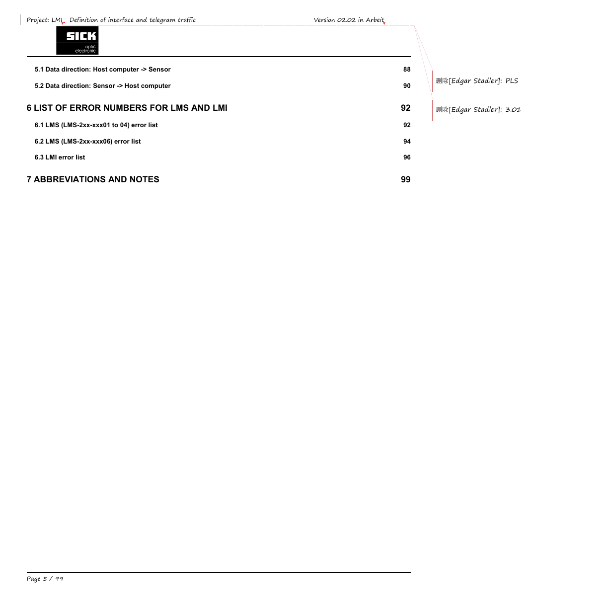
Project: LMI Definition of interface and telegram traffic Version 02.02 in Arbeit 5.1 Data direction: Host computer -> Sensor 5.2 Data direction: Sensor -> Host computer 6 LIST OF ERROR NUMBERS FOR LMS AND LMI 6.1 LMS (LMS-2xx-xxx01 to 04) error list 6.2 LMS (LMS-2xx-xxx06) error list 6.3 LMI error list 7 ABBREVIATIONS AND NOTES 删除[Edgar Stadler]: PLS 删除[Edgar Stadler]: 3.01 88 90 92 92 94 96 99 Page 5 / 99
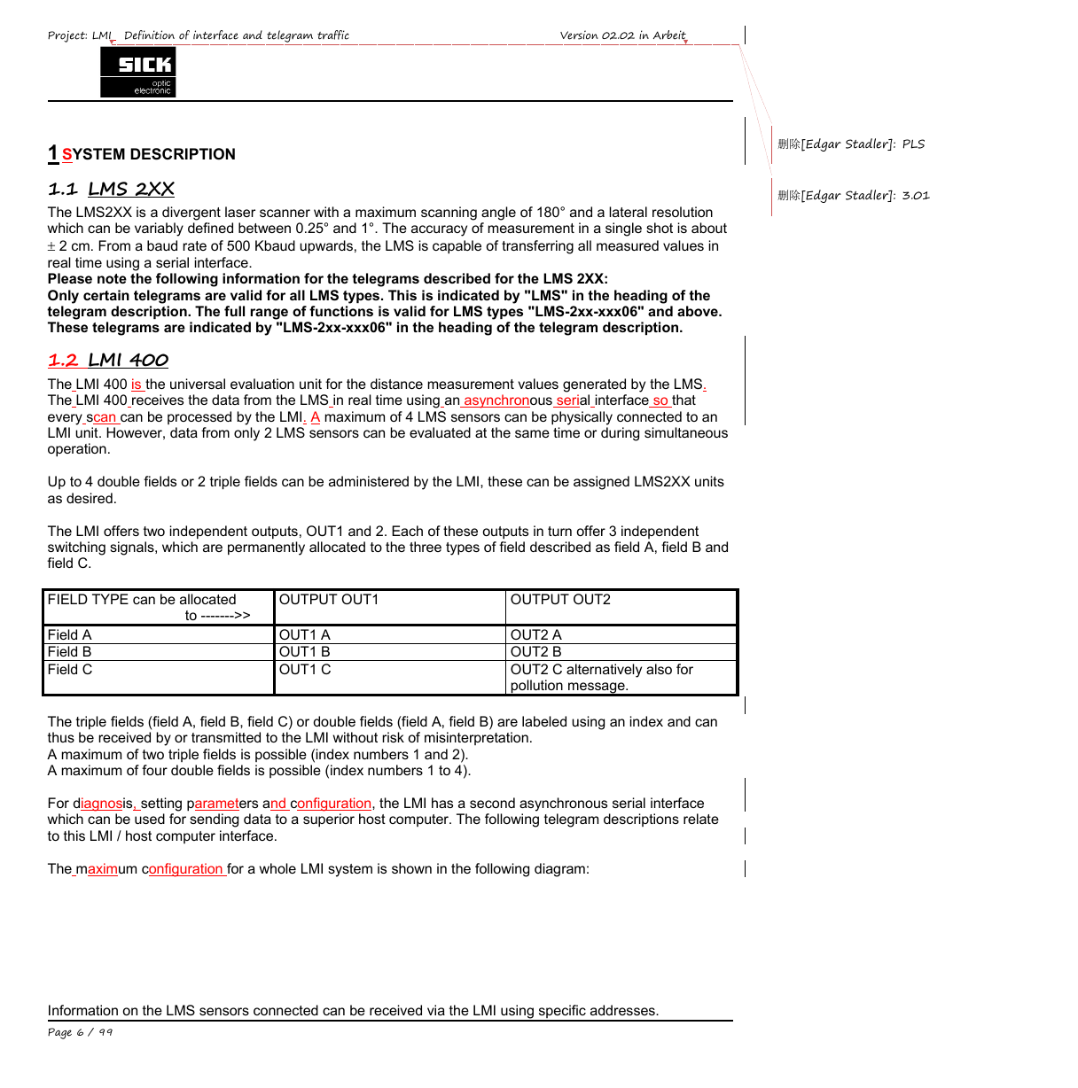
删除[Edgar Stadler]: PLS 删除[Edgar Stadler]: 3.01 Project: LMI Definition of interface and telegram traffic Version 02.02 in Arbeit 1 SYSTEM DESCRIPTION 1.1 LMS 2XX The LMS2XX is a divergent laser scanner with a maximum scanning angle of 180° and a lateral resolution which can be variably defined between 0.25° and 1°. The accuracy of measurement in a single shot is about  2 cm. From a baud rate of 500 Kbaud upwards, the LMS is capable of transferring all measured values in real time using a serial interface. Please note the following information for the telegrams described for the LMS 2XX: Only certain telegrams are valid for all LMS types. This is indicated by "LMS" in the heading of the telegram description. The full range of functions is valid for LMS types "LMS-2xx-xxx06" and above. These telegrams are indicated by "LMS-2xx-xxx06" in the heading of the telegram description. 1.2 LMI 400 The LMI 400 is the universal evaluation unit for the distance measurement values generated by the LMS. The LMI 400 receives the data from the LMS in real time using an asynchronous serial interface so that every scan can be processed by the LMI. A maximum of 4 LMS sensors can be physically connected to an LMI unit. However, data from only 2 LMS sensors can be evaluated at the same time or during simultaneous operation. Up to 4 double fields or 2 triple fields can be administered by the LMI, these can be assigned LMS2XX units as desired. The LMI offers two independent outputs, OUT1 and 2. Each of these outputs in turn offer 3 independent switching signals, which are permanently allocated to the three types of field described as field A, field B and field C. FIELD TYPE can be allocated to ------->> Field A Field B Field C OUTPUT OUT1 OUTPUT OUT2 OUT1 A OUT1 B OUT1 C OUT2 A OUT2 B OUT2 C alternatively also for pollution message. The triple fields (field A, field B, field C) or double fields (field A, field B) are labeled using an index and can thus be received by or transmitted to the LMI without risk of misinterpretation. A maximum of two triple fields is possible (index numbers 1 and 2). A maximum of four double fields is possible (index numbers 1 to 4). For diagnosis, setting parameters and configuration, the LMI has a second asynchronous serial interface which can be used for sending data to a superior host computer. The following telegram descriptions relate to this LMI / host computer interface. The maximum configuration for a whole LMI system is shown in the following diagram: Information on the LMS sensors connected can be received via the LMI using specific addresses. Page 6 / 99
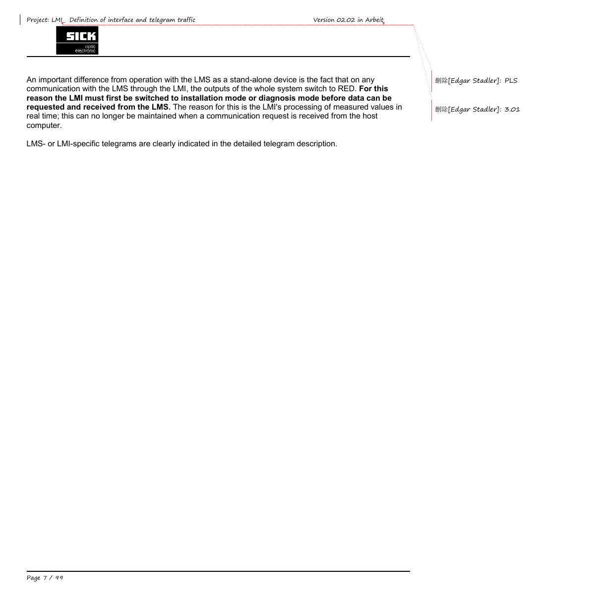
Project: LMI Definition of interface and telegram traffic Version 02.02 in Arbeit An important difference from operation with the LMS as a stand-alone device is the fact that on any communication with the LMS through the LMI, the outputs of the whole system switch to RED. For this reason the LMI must first be switched to installation mode or diagnosis mode before data can be requested and received from the LMS. The reason for this is the LMI's processing of measured values in real time; this can no longer be maintained when a communication request is received from the host computer. 删除[Edgar Stadler]: PLS 删除[Edgar Stadler]: 3.01 LMS- or LMI-specific telegrams are clearly indicated in the detailed telegram description. Page 7 / 99
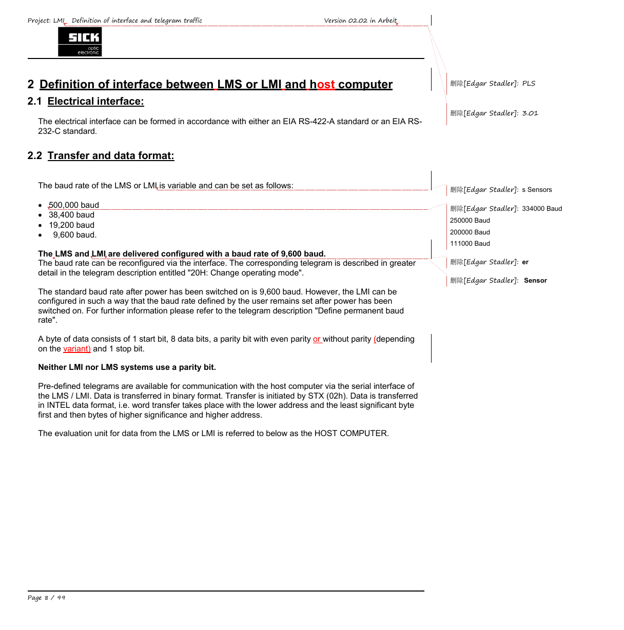
Project: LMI Definition of interface and telegram traffic Version 02.02 in Arbeit 2 Definition of interface between LMS or LMI and host computer 2.1 Electrical interface: The electrical interface can be formed in accordance with either an EIA RS-422-A standard or an EIA RS- 232-C standard. 删除[Edgar Stadler]: PLS 删除[Edgar Stadler]: 3.01 2.2 Transfer and data format: The baud rate of the LMS or LMI is variable and can be set as follows:  500,000 baud  38,400 baud  19,200 baud 9,600 baud.  The LMS and LMI are delivered configured with a baud rate of 9,600 baud. The baud rate can be reconfigured via the interface. The corresponding telegram is described in greater detail in the telegram description entitled "20H: Change operating mode". The standard baud rate after power has been switched on is 9,600 baud. However, the LMI can be configured in such a way that the baud rate defined by the user remains set after power has been switched on. For further information please refer to the telegram description "Define permanent baud rate". A byte of data consists of 1 start bit, 8 data bits, a parity bit with even parity or without parity (depending on the variant) and 1 stop bit. Neither LMI nor LMS systems use a parity bit. Pre-defined telegrams are available for communication with the host computer via the serial interface of the LMS / LMI. Data is transferred in binary format. Transfer is initiated by STX (02h). Data is transferred in INTEL data format, i.e. word transfer takes place with the lower address and the least significant byte first and then bytes of higher significance and higher address. The evaluation unit for data from the LMS or LMI is referred to below as the HOST COMPUTER. 删除[Edgar Stadler]: s Sensors 334000 Baud 删除[Edgar Stadler]: 250000 Baud 200000 Baud 111000 Baud 删除[Edgar Stadler]: er 删除[Edgar Stadler]: Sensor Page 8 / 99
分享到:
收藏