GLARE
GROUND CONTROL STATION (GCS)
1.1
SYSTEM OVERVIEW
The Ground Control Station (GCS) provides a portable platform allowing the
planning, control, and analysis of one or multiple UAV‟s and their associated
missions. The system design is targeted at providing a high level of situational
awareness coupled with the ability to easily and comprehensively carry out
mission planning and data analysis routines in the field, without the need to relay
the data back to a central command. The system has been designed to interface
with an automatic tracking antenna system (ATAS) to provide short to medium
range communications (<30km) to the GLARE UAV.
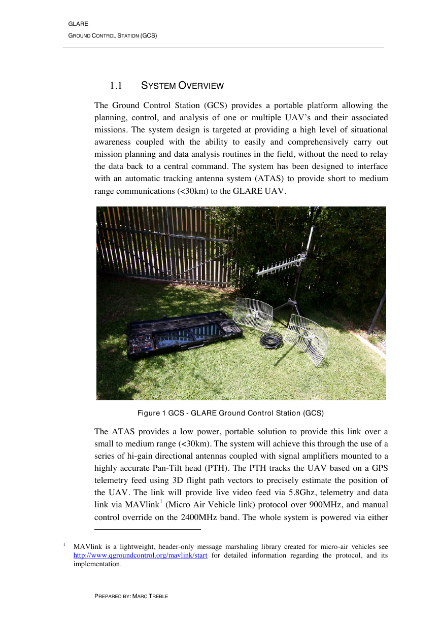
Figure 1 GCS - GLARE Ground Control Station (GCS)
The ATAS provides a low power, portable solution to provide this link over a
small to medium range (<30km). The system will achieve this through the use of a
series of hi-gain directional antennas coupled with signal amplifiers mounted to a
highly accurate Pan-Tilt head (PTH). The PTH tracks the UAV based on a GPS
telemetry feed using 3D flight path vectors to precisely estimate the position of
the UAV. The link will provide live video feed via 5.8Ghz, telemetry and data
link via MAVlink1 (Micro Air Vehicle link) protocol over 900MHz, and manual
control override on the 2400MHz band. The whole system is powered via either
1 MAVlink is a lightweight, header-only message marshaling library created for micro-air vehicles see
http://www.qgroundcontrol.org/mavlink/start for detailed information regarding the protocol, and its
implementation.
PREPARED BY: MARC TREBLE
�
GLARE
GROUND CONTROL STATION (GCS)
by the internal Lithium Ion battery pack or an external 12V source. The GCS‟s
control inputs include; two (2) 17" rugged multi touch monitors, weatherproof
keyboard, and flight control joystick and throttle for manual mode (drone)
operation. Data storage consists of an on-board hard drive with external high
speed connectors for backup and redundancy.
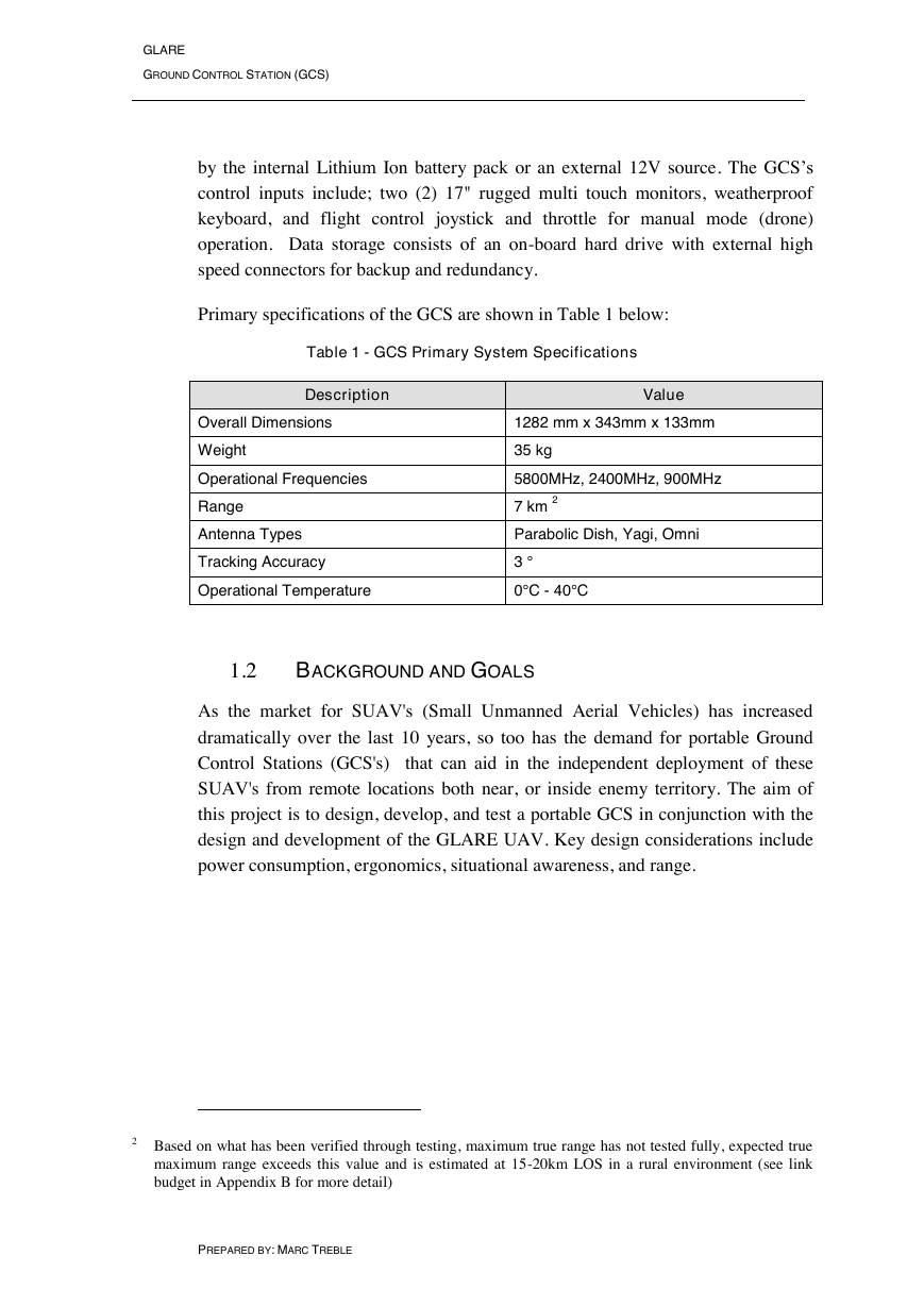
Primary specifications of the GCS are shown in Table 1 below:
Table 1 - GCS Primary System Specifications
Description
Value
Overall Dimensions
1282 mm x 343mm x 133mm
Weight
35 kg
Operational Frequencies
5800MHz, 2400MHz, 900MHz
Range
Antenna Types
Tracking Accuracy
Operational Temperature
7 km 2
Parabolic Dish, Yagi, Omni
3 °
0°C - 40°C
1.2
BACKGROUND AND GOALS
As the market for SUAV's (Small Unmanned Aerial Vehicles) has increased
dramatically over the last 10 years, so too has the demand for portable Ground
Control Stations (GCS's) that can aid in the independent deployment of these
SUAV's from remote locations both near, or inside enemy territory. The aim of
this project is to design, develop, and test a portable GCS in conjunction with the
design and development of the GLARE UAV. Key design considerations include
power consumption, ergonomics, situational awareness, and range.
2 Based on what has been verified through testing, maximum true range has not tested fully, expected true
maximum range exceeds this value and is estimated at 15-20km LOS in a rural environment (see link
budget in Appendix B for more detail)
PREPARED BY: MARC TREBLE
�
GLARE
GROUND CONTROL STATION (GCS)
Project goals for the development of the GLARE UAV Ground Control Station
are as follow:
1. Design, build and test a Ground Control Station (GCS) capable of
successfully handling the mission planning, control, and data analysis of
the GLARE UAV.
2. Design, build and test a functional Automatic Antenna Tracking System
(ATAS)
3. Develop and functioning software system to allow the tracking of the
GLARE UAV by the ATAS module.
1.3
APPLICATIONS FOR PORTABLE UAV GROUND CONTROL
STATIONS
The applications of portable ground control stations has grown substantially as the
applications for UAV use continues to be explored and expanded. UAV‟s are now
used in a number of applications outside the military including natural disaster
damage assessment, search and rescue, border patrol, crop monitoring, aerial
photography and videography, and many more. In each case, there is application
for a portable GCS to be used to deploy and control the UAV.
1.4
CHALLENGES
Gun launched UAV's present a number of difficulties when considering methods
of establishing solid and secure data links. The small size of the UAV means
conventional methods of long range communication larger UAV's employ cannot
be considered. The UAV is shielded inside the shell during the launch and prior to
UAV deployment, this prevents communication being established with the UAV
until after deployment. This presents the unique challenge of gaining a
communications link with the UAV once it has been deployed in a minimal
timeframe. Other challenges include keeping the system portable, while still
maximising the operational awareness of the user(s), maximising stand-alone
system endurance without compromising weight, and integrating all subsystems
together inside a stand-alone module.
PREPARED BY: MARC TREBLE
�
GLARE
GROUND CONTROL STATION (GCS)
1.5
REQUIREMENTS
1.5.1 Functionality Requirements
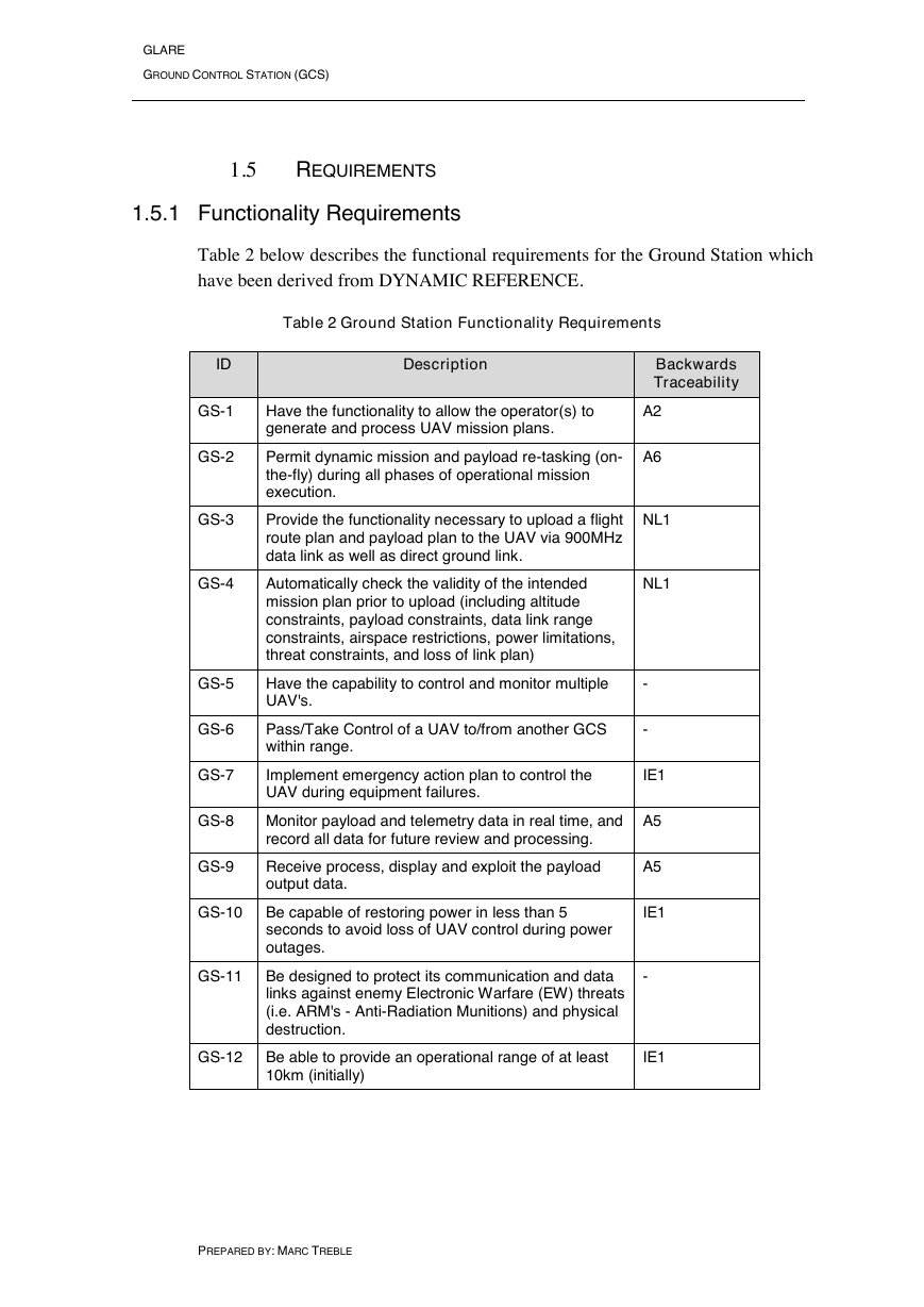
Table 2 below describes the functional requirements for the Ground Station which
have been derived from DYNAMIC REFERENCE.
Table 2 Ground Station Functionality Requirements
Description
Backwards
Traceability
Have the functionality to allow the operator(s) to
generate and process UAV mission plans.
Permit dynamic mission and payload re-tasking (on-
the-fly) during all phases of operational mission
execution.
Provide the functionality necessary to upload a flight
route plan and payload plan to the UAV via 900MHz
data link as well as direct ground link.
Automatically check the validity of the intended
mission plan prior to upload (including altitude
constraints, payload constraints, data link range
constraints, airspace restrictions, power limitations,
threat constraints, and loss of link plan)
Have the capability to control and monitor multiple
UAV's.
Pass/Take Control of a UAV to/from another GCS
within range.
Implement emergency action plan to control the
UAV during equipment failures.
Monitor payload and telemetry data in real time, and
record all data for future review and processing.
Receive process, display and exploit the payload
output data.
A2
A6
NL1
NL1
-
-
IE1
A5
A5
ID
GS-1
GS-2
GS-3
GS-4
GS-5
GS-6
GS-7
GS-8
GS-9
GS-10 Be capable of restoring power in less than 5
IE1
seconds to avoid loss of UAV control during power
outages.
GS-11 Be designed to protect its communication and data
-
links against enemy Electronic Warfare (EW) threats
(i.e. ARM's - Anti-Radiation Munitions) and physical
destruction.
GS-12 Be able to provide an operational range of at least
IE1
10km (initially)
PREPARED BY: MARC TREBLE
�
GLARE
GROUND CONTROL STATION (GCS)
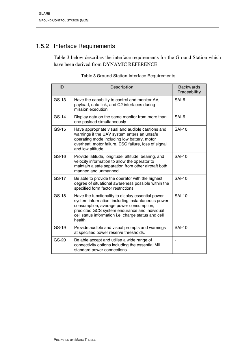
1.5.2 Interface Requirements
Table 3 below describes the interface requirements for the Ground Station which
have been derived from DYNAMIC REFERENCE.
Table 3 Ground Station Interface Requirements
Description
Have the capability to control and monitor AV,
payload, data link, and C2 interfaces during
mission execution
Backwards
Traceability
SAI-6
Display data on the same monitor from more than
one payload simultaneously
SAI-6
Have appropriate visual and audible cautions and
warnings if the UAV system enters an unsafe
operating mode including low battery, motor
overheat, motor failure, ESC failure, loss of signal
and low altitude.
Provide latitude, longitude, altitude, bearing, and
velocity information to allow the operator to
maintain a safe separation from other aircraft both
manned and unmanned.
Be able to provide the operator with the highest
degree of situational awareness possible within the
specified form factor restrictions.
Have the functionality to display essential power
system information, including instantaneous power
consumption, average power consumption,
predicted GCS system endurance and individual
cell status information i.e. charge status and cell
health.
SAI-10
SAI-10
SAI-10
SAI-10
Provide audible and visual prompts and warnings
at specified power reserve thresholds.
SAI-10
Be able accept and utilise a wide range of
connectivity options including the essential MIL
standard power connections.
-
ID
GS-13
GS-14
GS-15
GS-16
GS-17
GS-18
GS-19
GS-20
PREPARED BY: MARC TREBLE
�
GLARE
GROUND CONTROL STATION (GCS)
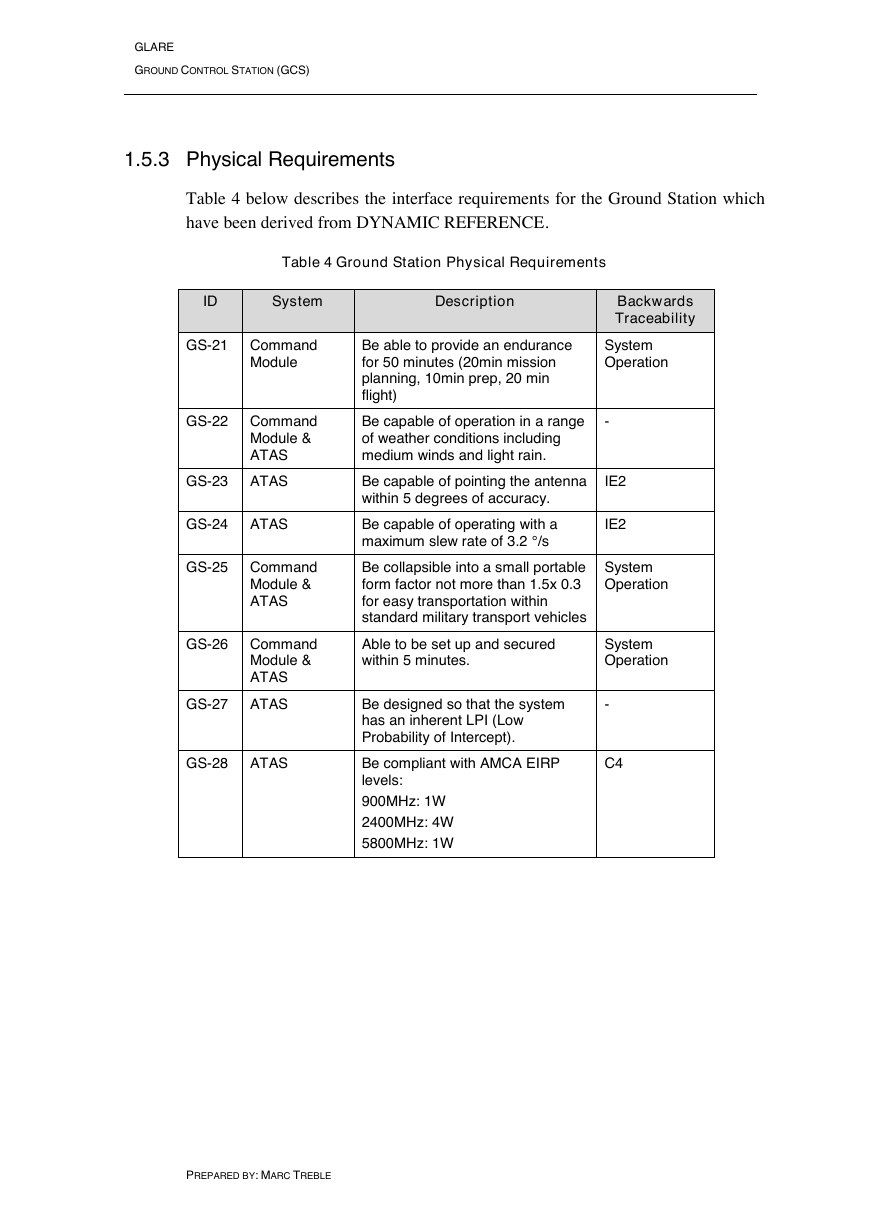
1.5.3 Physical Requirements
Table 4 below describes the interface requirements for the Ground Station which
have been derived from DYNAMIC REFERENCE.
Table 4 Ground Station Physical Requirements
ID
System
Description
GS-21 Command
Module
Be able to provide an endurance
for 50 minutes (20min mission
planning, 10min prep, 20 min
flight)
Backwards
Traceability
System
Operation
GS-22 Command
Module &
ATAS
Be capable of operation in a range
of weather conditions including
medium winds and light rain.
-
GS-23 ATAS
GS-24 ATAS
GS-25 Command
Module &
ATAS
GS-26 Command
Module &
ATAS
GS-27 ATAS
GS-28 ATAS
Be capable of pointing the antenna
within 5 degrees of accuracy.
Be capable of operating with a
maximum slew rate of 3.2 °/s
IE2
IE2
Be collapsible into a small portable
form factor not more than 1.5x 0.3
for easy transportation within
standard military transport vehicles
System
Operation
Able to be set up and secured
within 5 minutes.
System
Operation
Be designed so that the system
has an inherent LPI (Low
Probability of Intercept).
Be compliant with AMCA EIRP
levels:
-
C4
900MHz: 1W
2400MHz: 4W
5800MHz: 1W
PREPARED BY: MARC TREBLE
�
GLARE
GROUND CONTROL STATION (GCS)
1.6
DESIGN CONSIDERATIONS
1.6.1 Overview
A number of design considerations were addressed in the ongoing design of the
GCS and ATAS modules. The following design considerations are comprised of
items that have affected the design but are not explicitly specified within the
design requirements.
1.6.2 Cost
As the project budget is restricted by the level of sponsorship from both the
University of Queensland and Australian Aerospace (AA) the system was
designed according to a set cost point. This has heavily influenced component
quality selection during the design process. Prioritisation was hence key to
ensuring the best system performance within budgetary constraints.
1.6.3 Ergonomics
In order to ensure that the end human user can operate the system comfortably and
in an efficient manner, much consideration has been given to the design of the
overall layout and ergonomics characteristics of the module.
1.6.3.1 Size and Weight
The overall size and weight of the GCS was considered during the design to
ensure the system was easy to use and transport.
Ergonomic statistics dictate that the average human is capable of lifting 95 kg,
however if the individual needs to lift this weight several times, or the package is
not conducive to lifting (i.e. requires bending) this is revised down to 20kg. As the
total system weight was expected to exceed this value, it was necessary to
consider designs that included transport aids to ensure the maximum ease of use.
The overall size of the system was also considered in order to ensure that it is able
to be transported around using standard methods of transport.
PREPARED BY: MARC TREBLE
�
GLARE
GROUND CONTROL STATION (GCS)
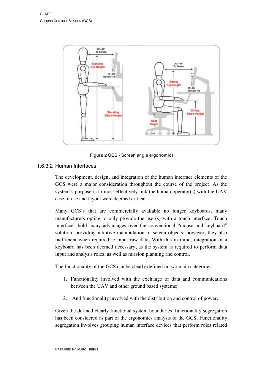
Figure 2 GCS - Screen angle ergonomics
1.6.3.2 Human Interfaces
The development, design, and integration of the human interface elements of the
GCS were a major consideration throughout the course of the project. As the
system‟s purpose is to most effectively link the human operator(s) with the UAV
ease of use and layout were deemed critical.
Many GCS‟s that are commercially available no longer keyboards, many
manufacturers opting to only provide the user(s) with a touch interface. Touch
interfaces hold many advantages over the conventional “mouse and keyboard”
solution, providing intuitive manipulation of screen objects; however, they also
inefficient when required to input raw data. With this in mind, integration of a
keyboard has been deemed necessary, as the system is required to perform data
input and analysis roles, as well as mission planning and control.
The functionality of the GCS can be clearly defined in two main categories:
1. Functionality involved with the exchange of data and communications
between the UAV and other ground based systems;
2. And functionality involved with the distribution and control of power.
Given the defined clearly functional system boundaries, functionality segregation
has been considered as part of the ergonomics analysis of the GCS. Functionality
segregation involves grouping human interface devices that perform roles related
PREPARED BY: MARC TREBLE
�


 2023年江西萍乡中考道德与法治真题及答案.doc
 2012年重庆南川中考生物真题及答案.doc
 2013年江西师范大学地理学综合及文艺理论基础考研真题.doc
 2020年四川甘孜小升初语文真题及答案I卷.doc
 2020年注册岩土工程师专业基础考试真题及答案.doc
 2023-2024学年福建省厦门市九年级上学期数学月考试题及答案.doc
 2021-2022学年辽宁省沈阳市大东区九年级上学期语文期末试题及答案.doc
 2022-2023学年北京东城区初三第一学期物理期末试卷及答案.doc
 2018上半年江西教师资格初中地理学科知识与教学能力真题及答案.doc
 2012年河北国家公务员申论考试真题及答案-省级.doc
 2020-2021学年江苏省扬州市江都区邵樊片九年级上学期数学第一次质量检测试题及答案.doc
 2022下半年黑龙江教师资格证中学综合素质真题及答案.doc