Chapter 2
Basics of Sigma-Delta Modulation
The principle of sigma-delta modulation, although widely used nowadays, was de-
veloped over a time span of more than 25 years. Initially the concept of oversam-
pling and noise shaping was not known and the search for an efficient technique for
transmitting voice signals digitally resulted in the Delta Modulator. Delta modula-
tion was independently invented at the ITT Laboratories by Deloraine et al. [11, 12]
the Philips Research Laboratories by de Jager [10], and at Bell Telephone Labs [8]
by Cutler. In 1954 the concept of oversampling and noise shaping was introduced
and patented by Cutler [9]. His objective was not to reduce the data rate of the signal
to transmit as in earlier published work, but to achieve a higher signal-to-noise ratio
in a limited frequency band. All the elements of modern sigma-delta modulation
are present in his invention, except for the digital decimation filter required for ob-
taining a Nyquist rate signal. The name Delta-Sigma Modulator (DSM) was finally
introduced in 1962 by Inose et al. [25, 26] in their papers discussing 1-bit converters.
By 1969 the realization of a digital decimation filter was feasible and described in a
publication by Goodman [16]. In 1974 Candy published the first complete multi-bit
Sigma-Delta Modulator (SDM) in [6]. Around the same time the name SDM was
introduced as an alternative for Delta-Sigma Modulator and since then both names
are in use. In this book the oversampled noise-shaping structure will be referred
to as SDM. According to the author SDM is the more appropriate name since the
integration or summing (the sigma) is over the difference (the delta).
In the 70’s, because of the initially limited performance of Sigma-Delta Modula-
tors, their main use was in encoding low frequency audio signals (analog-to-digital
conversion) using a 1-bit quantizer and a first or a second order loop filter. The
creation of black and white images for print from a gray scale input was another ap-
plication where Sigma-Delta noise-shaping techniques were used (digital-to-digital
conversion). Since then a lot of research on improving SDM performance has been
performed and great improvements have been realized. Nowadays top of the line
SDM based analog-to-digital converters (ADCs) use a multi-bit quantizer and a
high-order loop filter and are capable of converting 10’s of MHz of bandwidth with
high dynamic range. Because of high power efficiency, Sigma-Delta based analog-
to-digital converters are used in the radio of mobile telephones. Another example
E. Janssen, A. van Roermund, Look-Ahead Based Sigma-Delta Modulation,
Analog Circuits and Signal Processing,
DOI 10.1007/978-94-007-1387-1_2, © Springer Science+Business Media B.V. 2011
5
�
6
2 Basics of Sigma-Delta Modulation
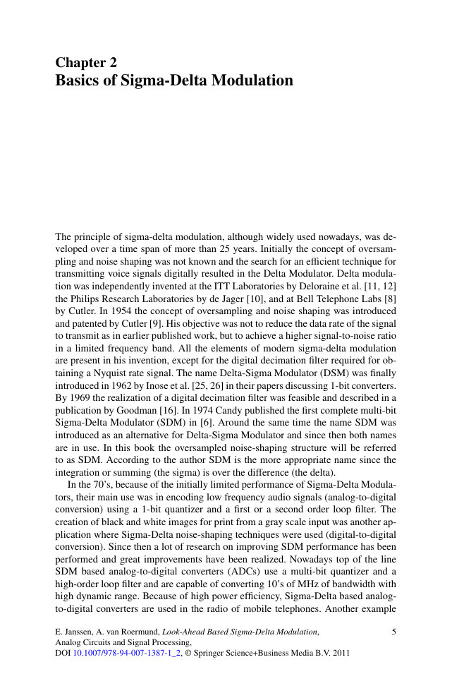
Fig. 2.1 Oversampling does not affect the signal power or total quantization noise power but
reduces the noise spectral density
of the efficient use of sigma-delta modulation techniques is the Super Audio CD
format which uses a 64 times oversampled 1-bit signal for delivering a 120 dB
signal-to-noise ratio (SNR) over the 0–20 kHz band. In this specific example the
decimation filter is omitted and the oversampled signal is directly stored as to min-
imize signal operations and therefore maximize the signal quality. An omnipresent
example of sigma-delta modulation in digital-to-analog conversion can be found in
portable audio playback devices, e.g. IPOD and MP3 players. The audio digital-to-
analog converter (DAC) in these devices realizes its performance using noise shap-
ing (NS) and pulse-width-modulation (PWM) or pulse-density-modulation (PDM)
techniques. These PWM/PDM signals are typically generated using a (modified)
digital SDM.
Although all these SDM solutions are optimized for a certain application and
context, they still share the same underlying basic principles of oversampling and
noise shaping. Oversampling is the process of taking more samples per second than
required on the basis of the Nyquist-Shannon criterion. By changing the sampling
rate the signal power and total quantization noise power is not affected. Therefore,
the signal to quantization noise ratio is not changed. However, the quantization noise
is spread over a larger frequency range, reducing the spectral density of the quanti-
zation noise. If now only the original Nyquist band is considered, the quantization
noise power is reduced by 3 dB for every doubling of the oversampling ratio and the
signal to quantization noise ratio is improved accordingly. This effect is illustrated
in Fig. 2.1 for an oversampling ratio (OSR) of 1, 2, and 4 times.
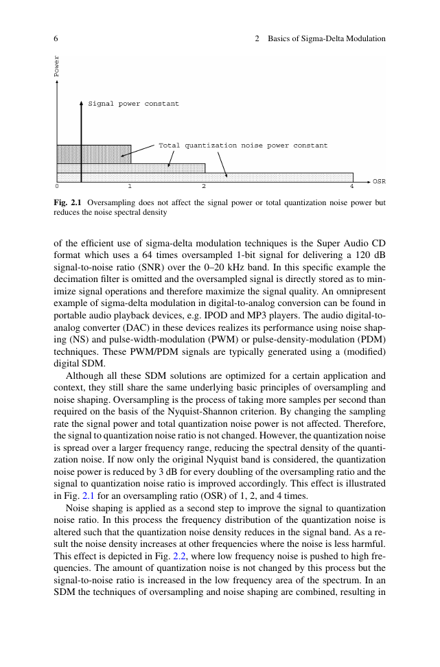
Noise shaping is applied as a second step to improve the signal to quantization
noise ratio. In this process the frequency distribution of the quantization noise is
altered such that the quantization noise density reduces in the signal band. As a re-
sult the noise density increases at other frequencies where the noise is less harmful.
This effect is depicted in Fig. 2.2, where low frequency noise is pushed to high fre-
quencies. The amount of quantization noise is not changed by this process but the
signal-to-noise ratio is increased in the low frequency area of the spectrum. In an
SDM the techniques of oversampling and noise shaping are combined, resulting in
�
2 Basics of Sigma-Delta Modulation
7
Fig. 2.2 Low frequency
noise is pushed to high
frequencies by noise shaping
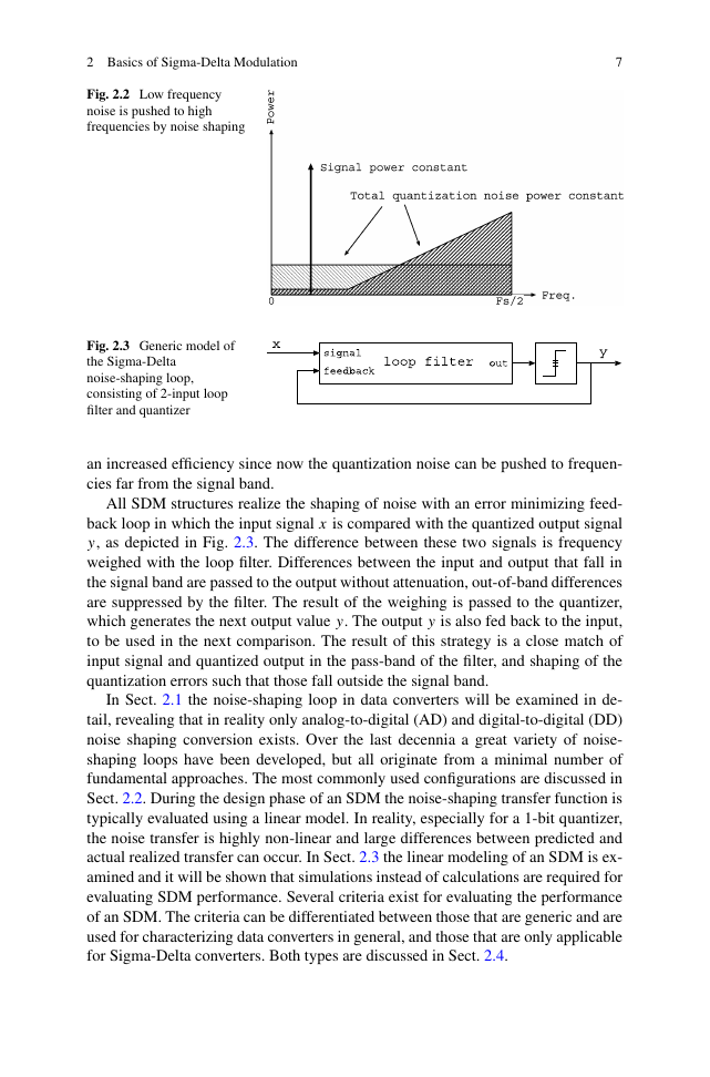
Fig. 2.3 Generic model of
the Sigma-Delta
noise-shaping loop,
consisting of 2-input loop
filter and quantizer
an increased efficiency since now the quantization noise can be pushed to frequen-
cies far from the signal band.
All SDM structures realize the shaping of noise with an error minimizing feed-
back loop in which the input signal x is compared with the quantized output signal
y, as depicted in Fig. 2.3. The difference between these two signals is frequency
weighed with the loop filter. Differences between the input and output that fall in
the signal band are passed to the output without attenuation, out-of-band differences
are suppressed by the filter. The result of the weighing is passed to the quantizer,
which generates the next output value y. The output y is also fed back to the input,
to be used in the next comparison. The result of this strategy is a close match of
input signal and quantized output in the pass-band of the filter, and shaping of the
quantization errors such that those fall outside the signal band.
In Sect. 2.1 the noise-shaping loop in data converters will be examined in de-
tail, revealing that in reality only analog-to-digital (AD) and digital-to-digital (DD)
noise shaping conversion exists. Over the last decennia a great variety of noise-
shaping loops have been developed, but all originate from a minimal number of
fundamental approaches. The most commonly used configurations are discussed in
Sect. 2.2. During the design phase of an SDM the noise-shaping transfer function is
typically evaluated using a linear model. In reality, especially for a 1-bit quantizer,
the noise transfer is highly non-linear and large differences between predicted and
actual realized transfer can occur. In Sect. 2.3 the linear modeling of an SDM is ex-
amined and it will be shown that simulations instead of calculations are required for
evaluating SDM performance. Several criteria exist for evaluating the performance
of an SDM. The criteria can be differentiated between those that are generic and are
used for characterizing data converters in general, and those that are only applicable
for Sigma-Delta converters. Both types are discussed in Sect. 2.4.
�
8
2 Basics of Sigma-Delta Modulation
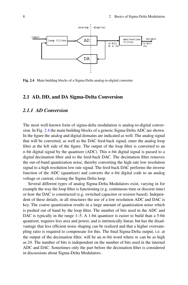
Fig. 2.4 Main building blocks of a Sigma-Delta analog-to-digital converter
2.1 AD, DD, and DA Sigma-Delta Conversion
2.1.1 AD Conversion
The most well-known form of sigma-delta modulation is analog-to-digital conver-
sion. In Fig. 2.4 the main building blocks of a generic Sigma-Delta ADC are shown.
In the figure the analog and digital domains are indicated as well. The analog signal
that will be converted, as well as the DAC feed-back signal, enter the analog loop
filter at the left side of the figure. The output of the loop filter is converted to an
n-bit digital signal by the quantizer (ADC). This n-bit digital signal is passed to a
digital decimation filter and to the feed-back DAC. The decimation filter removes
the out-of-band quantization noise, thereby converting the high rate low resolution
signal to a high resolution low rate signal. The feed-back DAC performs the inverse
function of the ADC (quantizer) and converts the n-bit digital code to an analog
voltage or current, closing the Sigma-Delta loop.
Several different types of analog Sigma-Delta Modulators exist, varying in for
example the way the loop filter is functioning (e.g. continuous time or discrete time)
or how the DAC is constructed (e.g. switched capacitor or resistor based). Indepen-
dent of these details, in all structures the use of a low resolution ADC and DAC is
key. The coarse quantization results in a large amount of quantization noise which
is pushed out of band by the loop filter. The number of bits used in the ADC and
DAC is typically in the range 1–5. A 1-bit quantizer is easier to build than a 5-bit
quantizer, requires less area and power, and is intrinsically linear, but has the disad-
vantage that less efficient noise shaping can be realized and that a higher oversam-
pling ratio is required to compensate for this. The final Sigma-Delta output, i.e. at
the output of the decimation filter, will be an m-bit word where m can be as high
as 24. The number of bits is independent on the number of bits used in the internal
ADC and DAC. Sometimes only the part before the decimation filter is considered
in discussions about Sigma-Delta Modulators.
�
2.1 AD, DD, and DA Sigma-Delta Conversion
9
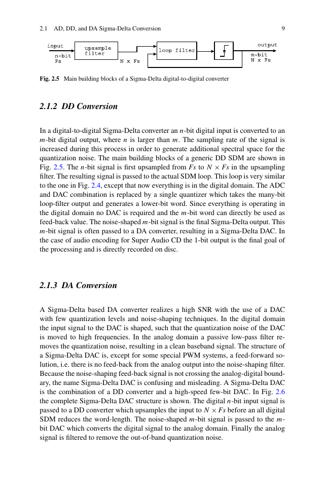
Fig. 2.5 Main building blocks of a Sigma-Delta digital-to-digital converter
2.1.2 DD Conversion
In a digital-to-digital Sigma-Delta converter an n-bit digital input is converted to an
m-bit digital output, where n is larger than m. The sampling rate of the signal is
increased during this process in order to generate additional spectral space for the
quantization noise. The main building blocks of a generic DD SDM are shown in
Fig. 2.5. The n-bit signal is first upsampled from Fs to N × Fs in the upsampling
filter. The resulting signal is passed to the actual SDM loop. This loop is very similar
to the one in Fig. 2.4, except that now everything is in the digital domain. The ADC
and DAC combination is replaced by a single quantizer which takes the many-bit
loop-filter output and generates a lower-bit word. Since everything is operating in
the digital domain no DAC is required and the m-bit word can directly be used as
feed-back value. The noise-shaped m-bit signal is the final Sigma-Delta output. This
m-bit signal is often passed to a DA converter, resulting in a Sigma-Delta DAC. In
the case of audio encoding for Super Audio CD the 1-bit output is the final goal of
the processing and is directly recorded on disc.
2.1.3 DA Conversion
A Sigma-Delta based DA converter realizes a high SNR with the use of a DAC
with few quantization levels and noise-shaping techniques. In the digital domain
the input signal to the DAC is shaped, such that the quantization noise of the DAC
is moved to high frequencies. In the analog domain a passive low-pass filter re-
moves the quantization noise, resulting in a clean baseband signal. The structure of
a Sigma-Delta DAC is, except for some special PWM systems, a feed-forward so-
lution, i.e. there is no feed-back from the analog output into the noise-shaping filter.
Because the noise-shaping feed-back signal is not crossing the analog-digital bound-
ary, the name Sigma-Delta DAC is confusing and misleading. A Sigma-Delta DAC
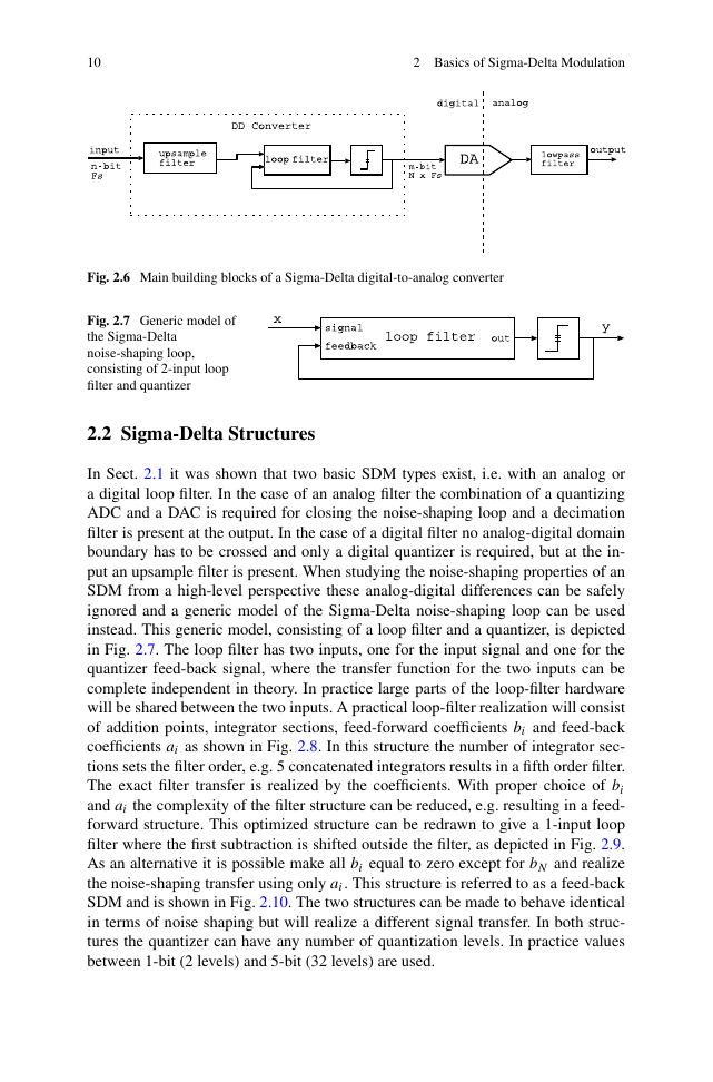
is the combination of a DD converter and a high-speed few-bit DAC. In Fig. 2.6
the complete Sigma-Delta DAC structure is shown. The digital n-bit input signal is
passed to a DD converter which upsamples the input to N × Fs before an all digital
SDM reduces the word-length. The noise-shaped m-bit signal is passed to the m-
bit DAC which converts the digital signal to the analog domain. Finally the analog
signal is filtered to remove the out-of-band quantization noise.
�
10
2 Basics of Sigma-Delta Modulation
Fig. 2.6 Main building blocks of a Sigma-Delta digital-to-analog converter
Fig. 2.7 Generic model of
the Sigma-Delta
noise-shaping loop,
consisting of 2-input loop
filter and quantizer
2.2 Sigma-Delta Structures
In Sect. 2.1 it was shown that two basic SDM types exist, i.e. with an analog or
a digital loop filter. In the case of an analog filter the combination of a quantizing
ADC and a DAC is required for closing the noise-shaping loop and a decimation
filter is present at the output. In the case of a digital filter no analog-digital domain
boundary has to be crossed and only a digital quantizer is required, but at the in-
put an upsample filter is present. When studying the noise-shaping properties of an
SDM from a high-level perspective these analog-digital differences can be safely
ignored and a generic model of the Sigma-Delta noise-shaping loop can be used
instead. This generic model, consisting of a loop filter and a quantizer, is depicted
in Fig. 2.7. The loop filter has two inputs, one for the input signal and one for the
quantizer feed-back signal, where the transfer function for the two inputs can be
complete independent in theory. In practice large parts of the loop-filter hardware
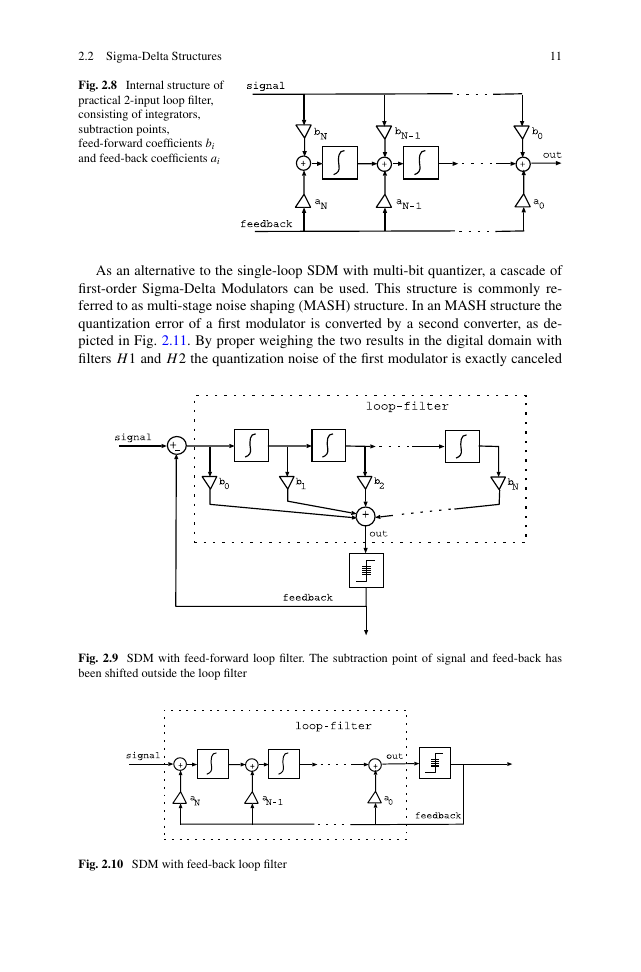
will be shared between the two inputs. A practical loop-filter realization will consist
of addition points, integrator sections, feed-forward coefficients bi and feed-back
coefficients ai as shown in Fig. 2.8. In this structure the number of integrator sec-
tions sets the filter order, e.g. 5 concatenated integrators results in a fifth order filter.
The exact filter transfer is realized by the coefficients. With proper choice of bi
and ai the complexity of the filter structure can be reduced, e.g. resulting in a feed-
forward structure. This optimized structure can be redrawn to give a 1-input loop
filter where the first subtraction is shifted outside the filter, as depicted in Fig. 2.9.
As an alternative it is possible make all bi equal to zero except for bN and realize
the noise-shaping transfer using only ai. This structure is referred to as a feed-back
SDM and is shown in Fig. 2.10. The two structures can be made to behave identical
in terms of noise shaping but will realize a different signal transfer. In both struc-
tures the quantizer can have any number of quantization levels. In practice values
between 1-bit (2 levels) and 5-bit (32 levels) are used.
�
2.2 Sigma-Delta Structures
Fig. 2.8 Internal structure of
practical 2-input loop filter,
consisting of integrators,
subtraction points,
feed-forward coefficients bi
and feed-back coefficients ai
11
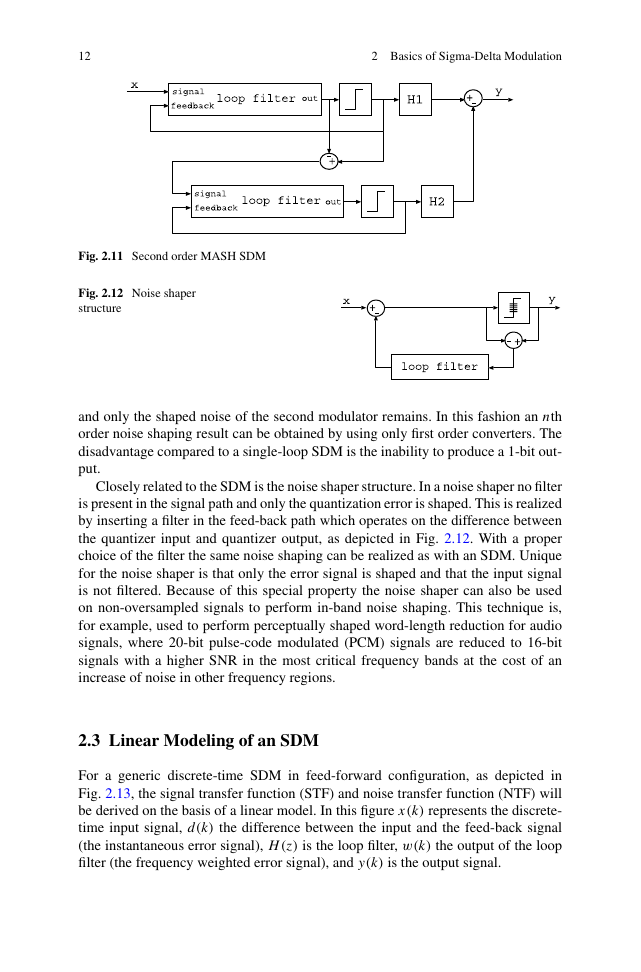
As an alternative to the single-loop SDM with multi-bit quantizer, a cascade of
first-order Sigma-Delta Modulators can be used. This structure is commonly re-
ferred to as multi-stage noise shaping (MASH) structure. In an MASH structure the
quantization error of a first modulator is converted by a second converter, as de-
picted in Fig. 2.11. By proper weighing the two results in the digital domain with
filters H 1 and H 2 the quantization noise of the first modulator is exactly canceled
Fig. 2.9 SDM with feed-forward loop filter. The subtraction point of signal and feed-back has
been shifted outside the loop filter
Fig. 2.10 SDM with feed-back loop filter
�
12
2 Basics of Sigma-Delta Modulation
Fig. 2.11 Second order MASH SDM
Fig. 2.12 Noise shaper
structure
and only the shaped noise of the second modulator remains. In this fashion an nth
order noise shaping result can be obtained by using only first order converters. The
disadvantage compared to a single-loop SDM is the inability to produce a 1-bit out-
put.
Closely related to the SDM is the noise shaper structure. In a noise shaper no filter
is present in the signal path and only the quantization error is shaped. This is realized
by inserting a filter in the feed-back path which operates on the difference between
the quantizer input and quantizer output, as depicted in Fig. 2.12. With a proper
choice of the filter the same noise shaping can be realized as with an SDM. Unique
for the noise shaper is that only the error signal is shaped and that the input signal
is not filtered. Because of this special property the noise shaper can also be used
on non-oversampled signals to perform in-band noise shaping. This technique is,
for example, used to perform perceptually shaped word-length reduction for audio
signals, where 20-bit pulse-code modulated (PCM) signals are reduced to 16-bit
signals with a higher SNR in the most critical frequency bands at the cost of an
increase of noise in other frequency regions.
2.3 Linear Modeling of an SDM
For a generic discrete-time SDM in feed-forward configuration, as depicted in
Fig. 2.13, the signal transfer function (STF) and noise transfer function (NTF) will
be derived on the basis of a linear model. In this figure x(k) represents the discrete-
time input signal, d(k) the difference between the input and the feed-back signal
(the instantaneous error signal), H (z) is the loop filter, w(k) the output of the loop
filter (the frequency weighted error signal), and y(k) is the output signal.
�


 2023年江西萍乡中考道德与法治真题及答案.doc
 2012年重庆南川中考生物真题及答案.doc
 2013年江西师范大学地理学综合及文艺理论基础考研真题.doc
 2020年四川甘孜小升初语文真题及答案I卷.doc
 2020年注册岩土工程师专业基础考试真题及答案.doc
 2023-2024学年福建省厦门市九年级上学期数学月考试题及答案.doc
 2021-2022学年辽宁省沈阳市大东区九年级上学期语文期末试题及答案.doc
 2022-2023学年北京东城区初三第一学期物理期末试卷及答案.doc
 2018上半年江西教师资格初中地理学科知识与教学能力真题及答案.doc
 2012年河北国家公务员申论考试真题及答案-省级.doc
 2020-2021学年江苏省扬州市江都区邵樊片九年级上学期数学第一次质量检测试题及答案.doc
 2022下半年黑龙江教师资格证中学综合素质真题及答案.doc