logo资料库

um0560_stm8_bootloader.pdf

第1页 / 共75页
第2页 / 共75页
第3页 / 共75页
第4页 / 共75页
第5页 / 共75页
第6页 / 共75页
第7页 / 共75页
第8页 / 共75页
资料共75页,剩余部分请下载后查看
1 Bootloader introduction
Table 1. STM8 groups featuring a bootloader
Table 2. STM8 groups without bootloader
1.1 Bootloader activation
Table 3. Bootloader versions for which bootloader activation flowchart is valid
Figure 1. Bootloader activation flowchart
Table 4. Initial checking
2 Peripheral settings
Table 5. Serial interfaces associated with STM8 devices
2.1 USART/UARTs settings
2.1.1 LINUART/UARTs in “reply” mode settings
2.2 SPI settings
2.3 CAN settings
Figure 2. CAN frame
3 Bootloader command set
Table 6. Bootloader commands
Table 7. Bootloader codes
3.1 Get command
3.1.1 Get command via USART/LINUART/UART1/ UART2/UART3
Figure 3. Get command via USART/LINUART/UART1/UART2/UART3 - host side
Figure 4. Get command via USART/LINUART/UART1/UART2/UART3 - device side
3.1.2 Get command via SPI
Figure 5. Get command via SPI - host side
Figure 6. Get command via SPI - device side
3.1.3 Get command via CAN
Figure 7. Get command via CAN - host side
Figure 8. Get command via CAN - device side
3.2 Read memory command
3.2.1 Read memory command via USART/LINUART/UART1/2/3
Figure 9. Read memory command via USART/LINUART/UART1/UART2/UART3 - host side
Figure 10. Read memory command via USART/LINUART/UART1/UART2/UART3 - device side
3.2.2 Read memory command via SPI
Figure 11. Read memory command via SPI - host side
Figure 12. Read memory command via SPI - device side
3.2.3 Read memory command via CAN
Figure 13. Read memory command via CAN - host side
Figure 14. Read memory command via CAN - device side
3.3 Erase memory command
3.3.1 Erase memory command via USART/LINUART/UART1/2/3
Figure 15. Erase memory command via USART/LINUART/UART1/2/3 - host side
Figure 16. Erase memory command via USART/LINUART/UART1/2/3 - device side
3.3.2 Erase memory command via SPI
Figure 17. Erase memory command via SPI - host side
Figure 18. Erase memory command via SPI - device side
3.3.3 Erase memory command via CAN
Figure 19. Erase memory command via CAN - host side
Figure 20. Erase memory command via CAN - device side
3.4 Write memory command
3.4.1 Write memory command via USART/LINUART/UART1/2/3
Figure 21. Write memory command via USART/LINUART/UART1/UART2/UART3 - host side
Figure 22. Write memory command via USART/LINUART/UART1/2/3 - device side
3.4.2 Write memory command via SPI
Figure 23. Write memory command via SPI - host side
Table 8. Examples of delay
Figure 24. Write memory command via SPI - device side
3.4.3 Write memory command via CAN
Figure 25. Write memory command via CAN - host side
Figure 26. Write memory command via CAN - device side
3.5 Speed command
3.5.1 Speed command via CAN
Figure 27. Speed command via CAN - host side
Figure 28. Speed command via CAN - device side
3.6 Go command
3.6.1 Go command via USART/LINUART/UART1/UART2/UART3
Figure 29. Go command via USART/LINUART/UART1/UART2/UART3 - host side
Figure 30. Go command via USART/LINUART/UART1/UART2/UART3 - device side
3.6.2 Go command via SPI
Figure 31. Go command via SPI - host side
Figure 32. Go command via SPI - device side
3.6.3 Go command via CAN
Figure 33. Go command via CAN - host side
Figure 34. Go command via CAN - device side
3.7 Sector codes
Table 9. STM8 sector codes
3.8 Software model (STM8AF, STM8AL, STM8L and STM8S Series)
3.8.1 RAM erase/write routines
4 Error management
Table 10. Error table
5 Programming time
Table 11. USART/LINUART/UART1/UART2/UART3 programming times
Table 12. SPI programming time
Table 13. CAN programming time
Appendix A How to upgrade ROP protected device
A.1 Rules for upgrading ROP protected devices
Appendix B Bootloader entry points
Table 14. Bootloader entry points
Appendix C SPI peripheral timing options
C.1 SPI with busy state checking
C.2 Modified erase/write RAM routines
Figure 35. Delay elimination in modified RAM routines
Appendix D PC software support
Figure 36. "Flash loader demonstrator" software
Appendix E Bootloader UART limitation
E.1 Description
E.1.1 UART automatic baudrate calculation
E.1.2 Description of UART limitation
E.2 Workaround for UART limitation
Appendix F Limitations and improvements versus bootloader versions
Table 15. Description of limitation, improvements and added features
Revision history
Table 16. Document revision history
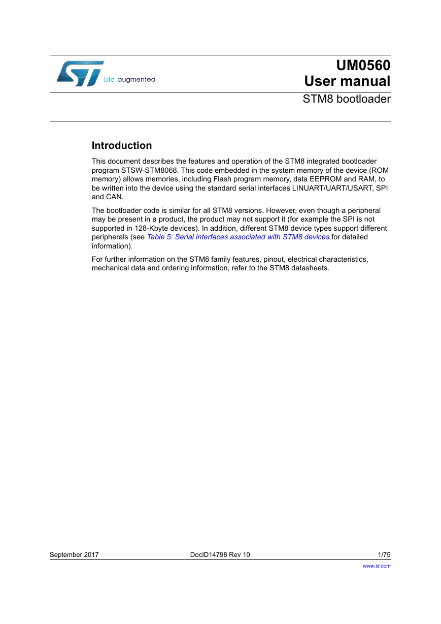
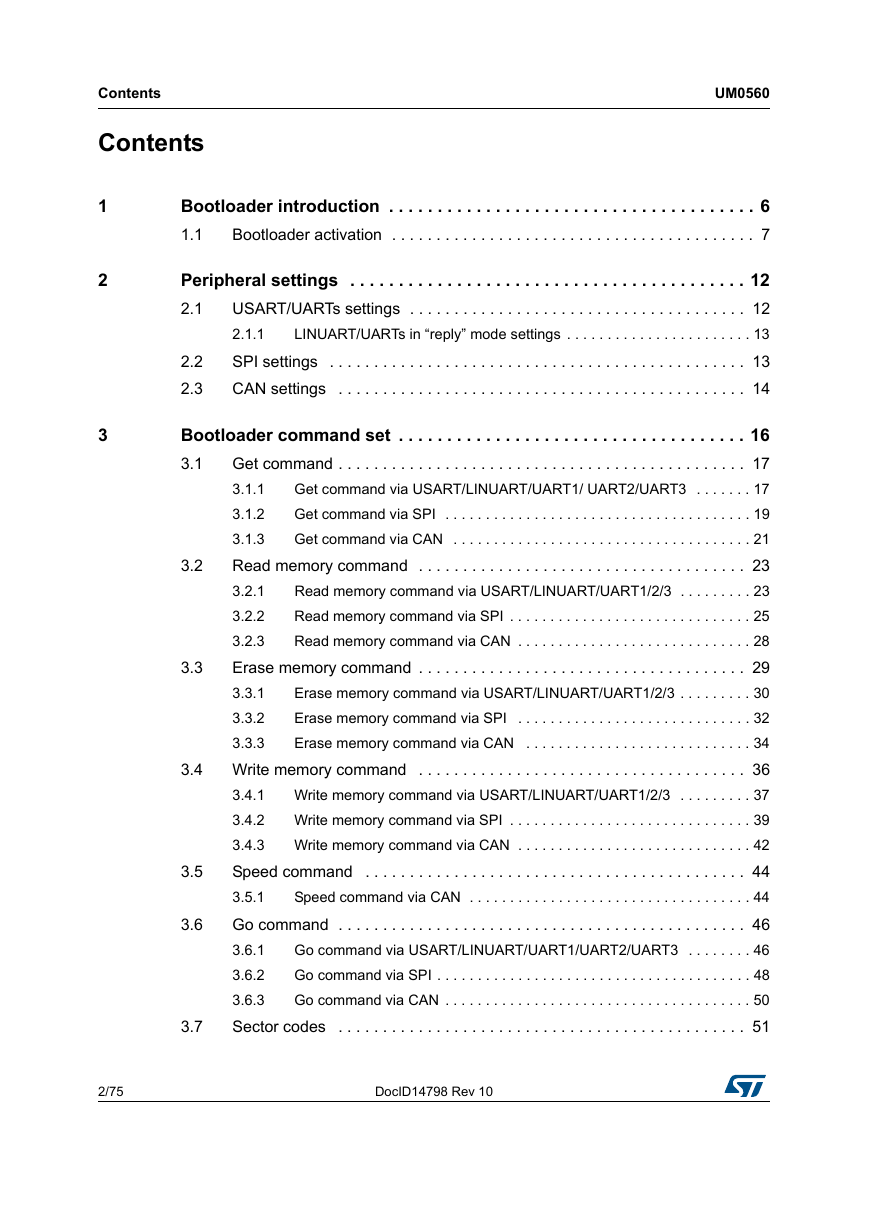
UM0560 User manual STM8 bootloader Introduction This document describes the features and operation of the STM8 integrated bootloader program STSW-STM8068. This code embedded in the system memory of the device (ROM memory) allows memories, including Flash program memory, data EEPROM and RAM, to be written into the device using the standard serial interfaces LINUART/UART/USART, SPI and CAN. The bootloader code is similar for all STM8 versions. However, even though a peripheral may be present in a product, the product may not support it (for example the SPI is not supported in 128-Kbyte devices). In addition, different STM8 device types support different peripherals (see Table 5: Serial interfaces associated with STM8 devices for detailed information). For further information on the STM8 family features, pinout, electrical characteristics, mechanical data and ordering information, refer to the STM8 datasheets. September 2017 DocID14798 Rev 10 1/75 www.st.com 1
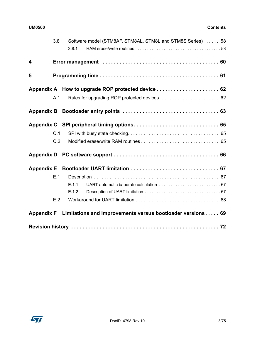
Contents Contents UM0560 1 2 3 Bootloader introduction . . . . . . . . . . . . . . . . . . . . . . . . . . . . . . . . . . . . . . 6 1.1 Bootloader activation . . . . . . . . . . . . . . . . . . . . . . . . . . . . . . . . . . . . . . . . . 7 Peripheral settings . . . . . . . . . . . . . . . . . . . . . . . . . . . . . . . . . . . . . . . . . 12 USART/UARTs settings . . . . . . . . . . . . . . . . . . . . . . . . . . . . . . . . . . . . . . 12 2.1 2.1.1 LINUART/UARTs in “reply” mode settings . . . . . . . . . . . . . . . . . . . . . . . 13 SPI settings . . . . . . . . . . . . . . . . . . . . . . . . . . . . . . . . . . . . . . . . . . . . . . . 13 CAN settings . . . . . . . . . . . . . . . . . . . . . . . . . . . . . . . . . . . . . . . . . . . . . . 14 2.2 2.3 3.2 Bootloader command set . . . . . . . . . . . . . . . . . . . . . . . . . . . . . . . . . . . . 16 Get command . . . . . . . . . . . . . . . . . . . . . . . . . . . . . . . . . . . . . . . . . . . . . . 17 3.1 3.1.1 Get command via USART/LINUART/UART1/ UART2/UART3 . . . . . . . 17 Get command via SPI . . . . . . . . . . . . . . . . . . . . . . . . . . . . . . . . . . . . . . 19 3.1.2 3.1.3 Get command via CAN . . . . . . . . . . . . . . . . . . . . . . . . . . . . . . . . . . . . . 21 Read memory command . . . . . . . . . . . . . . . . . . . . . . . . . . . . . . . . . . . . . 23 Read memory command via USART/LINUART/UART1/2/3 . . . . . . . . . 23 3.2.1 3.2.2 Read memory command via SPI . . . . . . . . . . . . . . . . . . . . . . . . . . . . . . 25 3.2.3 Read memory command via CAN . . . . . . . . . . . . . . . . . . . . . . . . . . . . . 28 Erase memory command . . . . . . . . . . . . . . . . . . . . . . . . . . . . . . . . . . . . . 29 3.3.1 Erase memory command via USART/LINUART/UART1/2/3 . . . . . . . . . 30 Erase memory command via SPI . . . . . . . . . . . . . . . . . . . . . . . . . . . . . 32 3.3.2 3.3.3 Erase memory command via CAN . . . . . . . . . . . . . . . . . . . . . . . . . . . . 34 3.4 Write memory command . . . . . . . . . . . . . . . . . . . . . . . . . . . . . . . . . . . . . 36 Write memory command via USART/LINUART/UART1/2/3 . . . . . . . . . 37 3.4.1 Write memory command via SPI . . . . . . . . . . . . . . . . . . . . . . . . . . . . . . 39 3.4.2 Write memory command via CAN . . . . . . . . . . . . . . . . . . . . . . . . . . . . . 42 3.4.3 Speed command . . . . . . . . . . . . . . . . . . . . . . . . . . . . . . . . . . . . . . . . . . . 44 3.5.1 Speed command via CAN . . . . . . . . . . . . . . . . . . . . . . . . . . . . . . . . . . . 44 Go command . . . . . . . . . . . . . . . . . . . . . . . . . . . . . . . . . . . . . . . . . . . . . . 46 Go command via USART/LINUART/UART1/UART2/UART3 . . . . . . . . 46 3.6.1 3.6.2 Go command via SPI . . . . . . . . . . . . . . . . . . . . . . . . . . . . . . . . . . . . . . . 48 3.6.3 Go command via CAN . . . . . . . . . . . . . . . . . . . . . . . . . . . . . . . . . . . . . . 50 Sector codes . . . . . . . . . . . . . . . . . . . . . . . . . . . . . . . . . . . . . . . . . . . . . . 51 3.7 3.3 3.5 3.6 2/75 DocID14798 Rev 10
UM0560 4 5 Contents 3.8 Software model (STM8AF, STM8AL, STM8L and STM8S Series) . . . . . 58 3.8.1 RAM erase/write routines . . . . . . . . . . . . . . . . . . . . . . . . . . . . . . . . . . . 58 Error management . . . . . . . . . . . . . . . . . . . . . . . . . . . . . . . . . . . . . . . . . 60 Programming time . . . . . . . . . . . . . . . . . . . . . . . . . . . . . . . . . . . . . . . . . . 61 Appendix A How to upgrade ROP protected device . . . . . . . . . . . . . . . . . . . . . . 62 Rules for upgrading ROP protected devices. . . . . . . . . . . . . . . . . . . . . . . 62 A.1 Appendix B Bootloader entry points . . . . . . . . . . . . . . . . . . . . . . . . . . . . . . . . . . 63 Appendix C SPI peripheral timing options. . . . . . . . . . . . . . . . . . . . . . . . . . . . . . 65 SPI with busy state checking. . . . . . . . . . . . . . . . . . . . . . . . . . . . . . . . . . . 65 Modified erase/write RAM routines . . . . . . . . . . . . . . . . . . . . . . . . . . . . . . 65 C.1 C.2 Appendix D PC software support . . . . . . . . . . . . . . . . . . . . . . . . . . . . . . . . . . . . . 66 E.1 Appendix E Bootloader UART limitation . . . . . . . . . . . . . . . . . . . . . . . . . . . . . . . 67 Description . . . . . . . . . . . . . . . . . . . . . . . . . . . . . . . . . . . . . . . . . . . . . . . . 67 E.1.1 UART automatic baudrate calculation . . . . . . . . . . . . . . . . . . . . . . . . . . 67 Description of UART limitation . . . . . . . . . . . . . . . . . . . . . . . . . . . . . . . . 67 E.1.2 E.2 Workaround for UART limitation . . . . . . . . . . . . . . . . . . . . . . . . . . . . . . . . 68 Appendix F Limitations and improvements versus bootloader versions. . . . . 69 Revision history . . . . . . . . . . . . . . . . . . . . . . . . . . . . . . . . . . . . . . . . . . . . . . . . . . . . 72 DocID14798 Rev 10 3/75 3
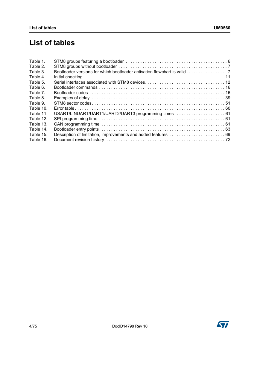
List of tables List of tables UM0560 Table 1. Table 2. Table 3. Table 4. Table 5. Table 6. Table 7. Table 8. Table 9. Table 10. Table 11. Table 12. Table 13. Table 14. Table 15. Table 16. STM8 groups featuring a bootloader . . . . . . . . . . . . . . . . . . . . . . . . . . . . . . . . . . . . . . . . . . 6 STM8 groups without bootloader . . . . . . . . . . . . . . . . . . . . . . . . . . . . . . . . . . . . . . . . . . . . . 7 Bootloader versions for which bootloader activation flowchart is valid . . . . . . . . . . . . . . . . . 7 Initial checking . . . . . . . . . . . . . . . . . . . . . . . . . . . . . . . . . . . . . . . . . . . . . . . . . . . . . . . . . . 11 Serial interfaces associated with STM8 devices. . . . . . . . . . . . . . . . . . . . . . . . . . . . . . . . . 12 Bootloader commands . . . . . . . . . . . . . . . . . . . . . . . . . . . . . . . . . . . . . . . . . . . . . . . . . . . . 16 Bootloader codes . . . . . . . . . . . . . . . . . . . . . . . . . . . . . . . . . . . . . . . . . . . . . . . . . . . . . . . . 16 Examples of delay . . . . . . . . . . . . . . . . . . . . . . . . . . . . . . . . . . . . . . . . . . . . . . . . . . . . . . . 39 STM8 sector codes. . . . . . . . . . . . . . . . . . . . . . . . . . . . . . . . . . . . . . . . . . . . . . . . . . . . . . . 51 Error table . . . . . . . . . . . . . . . . . . . . . . . . . . . . . . . . . . . . . . . . . . . . . . . . . . . . . . . . . . . . . . 60 USART/LINUART/UART1/UART2/UART3 programming times . . . . . . . . . . . . . . . . . . . . . 61 SPI programming time . . . . . . . . . . . . . . . . . . . . . . . . . . . . . . . . . . . . . . . . . . . . . . . . . . . . 61 CAN programming time . . . . . . . . . . . . . . . . . . . . . . . . . . . . . . . . . . . . . . . . . . . . . . . . . . . 61 Bootloader entry points. . . . . . . . . . . . . . . . . . . . . . . . . . . . . . . . . . . . . . . . . . . . . . . . . . . . 63 Description of limitation, improvements and added features . . . . . . . . . . . . . . . . . . . . . . . 69 Document revision history . . . . . . . . . . . . . . . . . . . . . . . . . . . . . . . . . . . . . . . . . . . . . . . . . 72 4/75 DocID14798 Rev 10
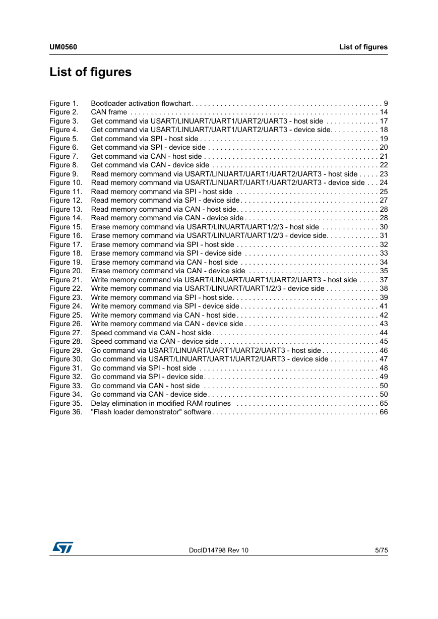
UM0560 List of figures List of figures Bootloader activation flowchart. . . . . . . . . . . . . . . . . . . . . . . . . . . . . . . . . . . . . . . . . . . . . . . 9 Figure 1. CAN frame . . . . . . . . . . . . . . . . . . . . . . . . . . . . . . . . . . . . . . . . . . . . . . . . . . . . . . . . . . . . . 14 Figure 2. Get command via USART/LINUART/UART1/UART2/UART3 - host side . . . . . . . . . . . . . 17 Figure 3. Get command via USART/LINUART/UART1/UART2/UART3 - device side. . . . . . . . . . . . 18 Figure 4. Get command via SPI - host side . . . . . . . . . . . . . . . . . . . . . . . . . . . . . . . . . . . . . . . . . . . . 19 Figure 5. Get command via SPI - device side . . . . . . . . . . . . . . . . . . . . . . . . . . . . . . . . . . . . . . . . . . 20 Figure 6. Get command via CAN - host side . . . . . . . . . . . . . . . . . . . . . . . . . . . . . . . . . . . . . . . . . . . 21 Figure 7. Get command via CAN - device side . . . . . . . . . . . . . . . . . . . . . . . . . . . . . . . . . . . . . . . . . 22 Figure 8. Figure 9. Read memory command via USART/LINUART/UART1/UART2/UART3 - host side . . . . . 23 Figure 10. Read memory command via USART/LINUART/UART1/UART2/UART3 - device side . . . 24 Figure 11. Read memory command via SPI - host side . . . . . . . . . . . . . . . . . . . . . . . . . . . . . . . . . . . 25 Figure 12. Read memory command via SPI - device side. . . . . . . . . . . . . . . . . . . . . . . . . . . . . . . . . . 27 Figure 13. Read memory command via CAN - host side. . . . . . . . . . . . . . . . . . . . . . . . . . . . . . . . . . . 28 Figure 14. Read memory command via CAN - device side . . . . . . . . . . . . . . . . . . . . . . . . . . . . . . . . . 28 Figure 15. Erase memory command via USART/LINUART/UART1/2/3 - host side . . . . . . . . . . . . . . 30 Figure 16. Erase memory command via USART/LINUART/UART1/2/3 - device side. . . . . . . . . . . . . 31 Figure 17. Erase memory command via SPI - host side . . . . . . . . . . . . . . . . . . . . . . . . . . . . . . . . . . . 32 Figure 18. Erase memory command via SPI - device side . . . . . . . . . . . . . . . . . . . . . . . . . . . . . . . . . 33 Figure 19. Erase memory command via CAN - host side . . . . . . . . . . . . . . . . . . . . . . . . . . . . . . . . . . 34 Figure 20. Erase memory command via CAN - device side . . . . . . . . . . . . . . . . . . . . . . . . . . . . . . . . 35 Figure 21. Write memory command via USART/LINUART/UART1/UART2/UART3 - host side . . . . . 37 Figure 22. Write memory command via USART/LINUART/UART1/2/3 - device side . . . . . . . . . . . . . 38 Figure 23. Write memory command via SPI - host side. . . . . . . . . . . . . . . . . . . . . . . . . . . . . . . . . . . . 39 Figure 24. Write memory command via SPI - device side . . . . . . . . . . . . . . . . . . . . . . . . . . . . . . . . . . 41 Figure 25. Write memory command via CAN - host side. . . . . . . . . . . . . . . . . . . . . . . . . . . . . . . . . . . 42 Figure 26. Write memory command via CAN - device side . . . . . . . . . . . . . . . . . . . . . . . . . . . . . . . . . 43 Figure 27. Speed command via CAN - host side. . . . . . . . . . . . . . . . . . . . . . . . . . . . . . . . . . . . . . . . . 44 Figure 28. Speed command via CAN - device side . . . . . . . . . . . . . . . . . . . . . . . . . . . . . . . . . . . . . . . 45 Figure 29. Go command via USART/LINUART/UART1/UART2/UART3 - host side . . . . . . . . . . . . . . 46 Figure 30. Go command via USART/LINUART/UART1/UART2/UART3 - device side . . . . . . . . . . . . 47 Figure 31. Go command via SPI - host side . . . . . . . . . . . . . . . . . . . . . . . . . . . . . . . . . . . . . . . . . . . . 48 Figure 32. Go command via SPI - device side. . . . . . . . . . . . . . . . . . . . . . . . . . . . . . . . . . . . . . . . . . . 49 Figure 33. Go command via CAN - host side . . . . . . . . . . . . . . . . . . . . . . . . . . . . . . . . . . . . . . . . . . . 50 Figure 34. Go command via CAN - device side. . . . . . . . . . . . . . . . . . . . . . . . . . . . . . . . . . . . . . . . . . 50 Figure 35. Delay elimination in modified RAM routines . . . . . . . . . . . . . . . . . . . . . . . . . . . . . . . . . . . 65 Figure 36. "Flash loader demonstrator" software. . . . . . . . . . . . . . . . . . . . . . . . . . . . . . . . . . . . . . . . . 66 DocID14798 Rev 10 5/75 5
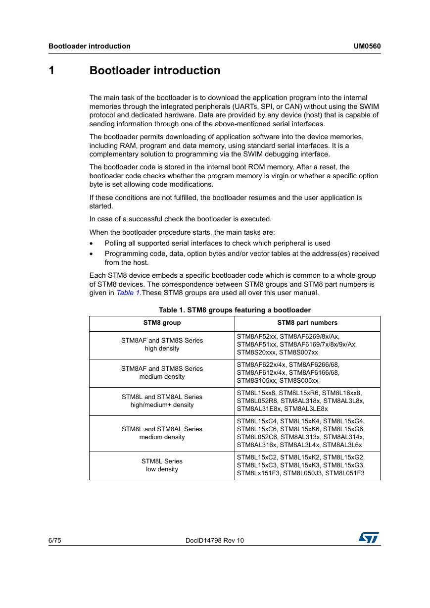
Bootloader introduction UM0560 1 Bootloader introduction The main task of the bootloader is to download the application program into the internal memories through the integrated peripherals (UARTs, SPI, or CAN) without using the SWIM protocol and dedicated hardware. Data are provided by any device (host) that is capable of sending information through one of the above-mentioned serial interfaces. The bootloader permits downloading of application software into the device memories, including RAM, program and data memory, using standard serial interfaces. It is a complementary solution to programming via the SWIM debugging interface. The bootloader code is stored in the internal boot ROM memory. After a reset, the bootloader code checks whether the program memory is virgin or whether a specific option byte is set allowing code modifications. If these conditions are not fulfilled, the bootloader resumes and the user application is started. In case of a successful check the bootloader is executed. When the bootloader procedure starts, the main tasks are: • • Polling all supported serial interfaces to check which peripheral is used Programming code, data, option bytes and/or vector tables at the address(es) received from the host. Each STM8 device embeds a specific bootloader code which is common to a whole group of STM8 devices. The correspondence between STM8 groups and STM8 part numbers is given in Table 1.These STM8 groups are used all over this user manual. Table 1. STM8 groups featuring a bootloader STM8 group STM8 part numbers STM8AF and STM8S Series high density STM8AF and STM8S Series medium density STM8L and STM8AL Series high/medium+ density STM8L and STM8AL Series medium density STM8L Series low density STM8AF52xx, STM8AF6269/8x/Ax, STM8AF51xx, STM8AF6169/7x/8x/9x/Ax, STM8S20xxx, STM8S007xx STM8AF622x/4x, STM8AF6266/68, STM8AF612x/4x, STM8AF6166/68, STM8S105xx, STM8S005xx STM8L15xx8, STM8L15xR6, STM8L16xx8, STM8L052R8, STM8AL318x, STM8AL3L8x, STM8AL31E8x, STM8AL3LE8x STM8L15xC4, STM8L15xK4, STM8L15xG4, STM8L15xC6, STM8L15xK6, STM8L15xG6, STM8L052C6, STM8AL313x, STM8AL314x, STM8AL316x, STM8AL3L4x, STM8AL3L6x STM8L15xC2, STM8L15xK2, STM8L15xG2, STM8L15xC3, STM8L15xK3, STM8L15xG3, STM8Lx151F3, STM8L050J3, STM8L051F3 6/75 DocID14798 Rev 10
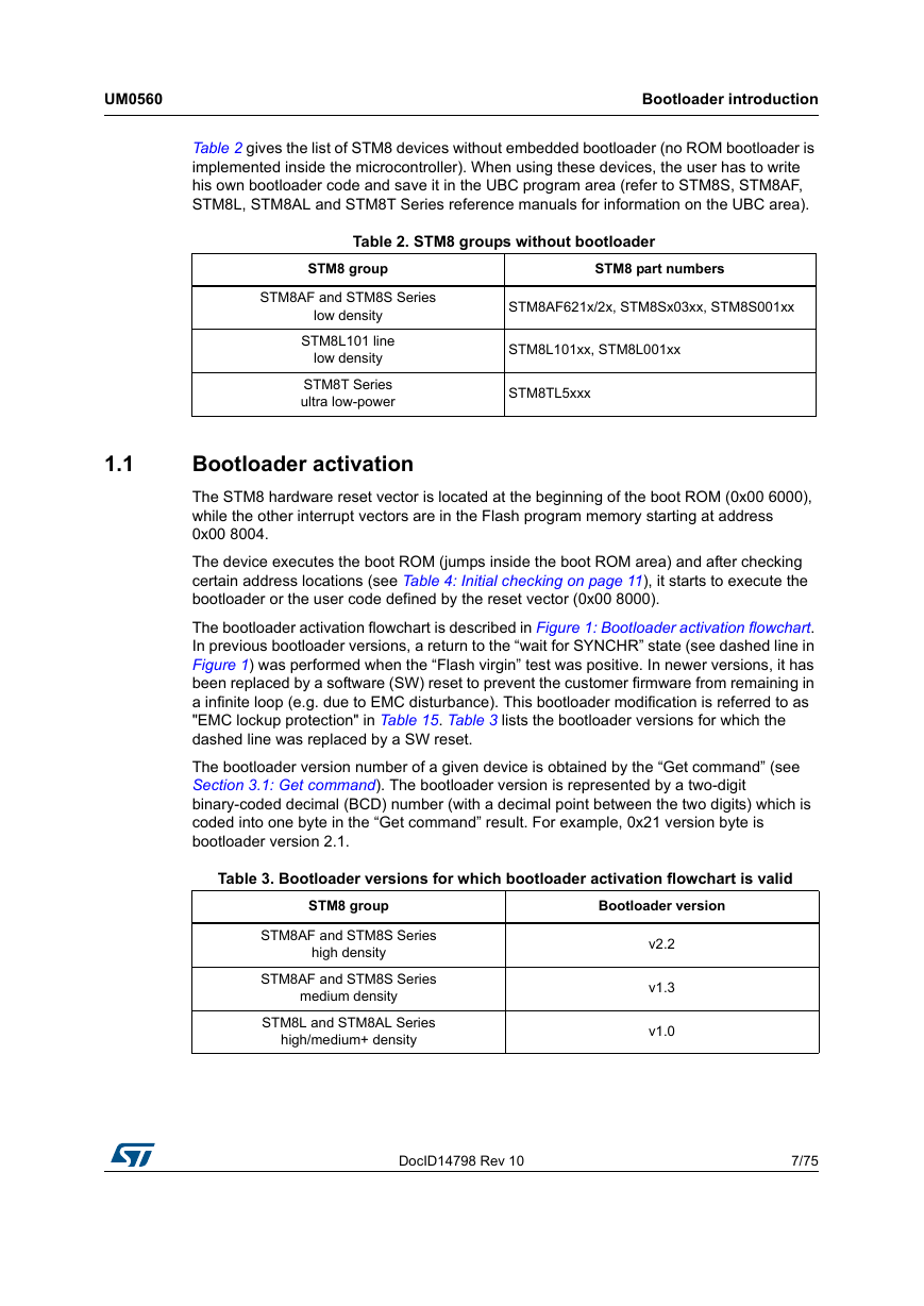
UM0560 Bootloader introduction 1.1 Table 2 gives the list of STM8 devices without embedded bootloader (no ROM bootloader is implemented inside the microcontroller). When using these devices, the user has to write his own bootloader code and save it in the UBC program area (refer to STM8S, STM8AF, STM8L, STM8AL and STM8T Series reference manuals for information on the UBC area). Table 2. STM8 groups without bootloader STM8 group STM8AF and STM8S Series low density STM8L101 line low density STM8T Series ultra low-power STM8 part numbers STM8AF621x/2x, STM8Sx03xx, STM8S001xx STM8L101xx, STM8L001xx STM8TL5xxx Bootloader activation The STM8 hardware reset vector is located at the beginning of the boot ROM (0x00 6000), while the other interrupt vectors are in the Flash program memory starting at address 0x00 8004. The device executes the boot ROM (jumps inside the boot ROM area) and after checking certain address locations (see Table 4: Initial checking on page 11), it starts to execute the bootloader or the user code defined by the reset vector (0x00 8000). The bootloader activation flowchart is described in Figure 1: Bootloader activation flowchart. In previous bootloader versions, a return to the “wait for SYNCHR” state (see dashed line in Figure 1) was performed when the “Flash virgin” test was positive. In newer versions, it has been replaced by a software (SW) reset to prevent the customer firmware from remaining in a infinite loop (e.g. due to EMC disturbance). This bootloader modification is referred to as "EMC lockup protection" in Table 15. Table 3 lists the bootloader versions for which the dashed line was replaced by a SW reset. The bootloader version number of a given device is obtained by the “Get command” (see Section 3.1: Get command). The bootloader version is represented by a two-digit binary-coded decimal (BCD) number (with a decimal point between the two digits) which is coded into one byte in the “Get command” result. For example, 0x21 version byte is bootloader version 2.1. Table 3. Bootloader versions for which bootloader activation flowchart is valid STM8 group STM8AF and STM8S Series high density STM8AF and STM8S Series medium density STM8L and STM8AL Series high/medium+ density Bootloader version v2.2 v1.3 v1.0 DocID14798 Rev 10 7/75 74
Bootloader introduction UM0560 Table 3. Bootloader versions for which bootloader activation flowchart is valid STM8 group Bootloader version STM8L and STM8AL Series medium density STM8L Series low density v1.2 v1.0 8/75 DocID14798 Rev 10
分享到:
收藏