logo资料库

ICM-42605.pdf

第1页 / 共97页
第2页 / 共97页
第3页 / 共97页
第4页 / 共97页
第5页 / 共97页
第6页 / 共97页
第7页 / 共97页
第8页 / 共97页
资料共97页,剩余部分请下载后查看
Table of Figures
Table of Tables
1 Introduction
1.1 Purpose and Scope
1.2 Product Overview
1.3 Applications
2 Features
2.1 Gyroscope Features
2.2 Accelerometer Features
2.3 Motion Features
2.4 Additional Features
3 Electrical Characteristics
3.1 Gyroscope Specifications
3.2 Accelerometer Specifications
3.3 Electrical Specifications
3.3.1 D.C. Electrical Characteristics
3.3.2 A.C. Electrical Characteristics
3.4 I2C Timing Characterization
3.5 SPI Timing Characterization – 4-Wire SPI Mode
3.6 SPI Timing Characterization – 3-Wire SPI Mode
3.7 Absolute Maximum Ratings
4 Applications Information
4.1 Pin Out Diagram and Signal Description
4.2 Typical Operating Circuit
4.3 Bill of Materials for External Components
4.4 System Block Diagram
4.5 Overview
4.6 Three-Axis MEMS Gyroscope with 16-bit ADCs and Signal Conditioning
4.7 Three-Axis MEMS Accelerometer with 16-bit ADCs and Signal Conditioning
4.8 I3C, I2C and SPI Host Interface
4.9 Self-Test
4.10 Clocking
4.11 Sensor Data Registers
4.12 Interrupts
4.13 Digital-Output Temperature Sensor
4.14 Bias and LDOs
4.15 Charge Pump
4.16 Standard Power Modes
5 Signal Path
5.1 Summary of Parameters Used to Configure the Signal Path
5.2 Notch Filter
Frequency of Notch Filter (each axis)
Bandwidth of Notch Filter (common to all axes)
5.3 Anti-Alias Filter
5.4 User Programmable Offset
5.5 UI Filter Block
1st Order Filter 3dB Bandwidth, Noise Bandwidth (NBW), Group Delay
2nd Order Filter 3dB Bandwidth, Noise Bandwidth (NBW), Group Delay
3rd Order Filter 3dB Bandwidth, Noise Bandwidth (NBW), Group Delay
5.6 ODR And FSR Selection
6 FIFO
6.1 Packet Structure
6.2 FIFO Header
6.3 Maximum FIFO Storage
6.4 FIFO Configuration Registers
7 Programmable Interrupts
8 APEX Motion Functions
8.1 APEX ODR Support
8.2 Pedometer Programming
8.3 Tilt Detection Programming
8.4 Tap Detection Programming
8.5 Wake on Motion Programming
8.6 Significant Motion Detection Programming
9 Digital Interface
9.1 I3C, I2C and SPI Serial Interfaces
9.2 I3C Interface
9.3 I2C Interface
9.4 I2C Communications Protocol
9.5 I2C Terms
9.6 SPI Interface
10 Assembly
10.1 Orientation of Axes
10.2 Package Dimensions
11 Part Number Package Marking
12 Use Notes
12.1 Accelerometer Mode Transitions
12.2 Accelerometer Low Power (LP) Mode Averaging Filter Setting
12.3 Settings for I2C, I3C, and SPI Operation
12.4 Notch Filter and Anti-Alias Filter Operation
13 Register Map
13.1 User Bank 0 Register Map
13.2 User Bank 1 Register Map
13.3 User Bank 2 Register Map
13.4 User Bank 4 Register Map
14 User Bank 0 Register Map – Descriptions
14.1 DEVICE_CONFIG
14.2 DRIVE_CONFIG
14.3 INT_CONFIG
14.4 FIFO_CONFIG
14.5 TEMP_DATA1
14.6 TEMP_DATA0
14.7 ACCEL_DATA_X1
14.8 ACCEL_DATA_X0
14.9 ACCEL_DATA_Y1
14.10 ACCEL_DATA_Y0
14.11 ACCEL_DATA_Z1
14.12 ACCEL_DATA_Z0
14.13 GYRO_DATA_X1
14.14 GYRO_DATA_X0
14.15 GYRO_DATA_Y1
14.16 GYRO_DATA_Y0
14.17 GYRO_DATA_Z1
14.18 GYRO_DATA_Z0
14.19 TMST_FSYNCH
14.20 TMST_FSYNCL
14.21 INT_STATUS
14.22 FIFO_COUNTH
14.23 FIFO_COUNTL
14.24 FIFO_DATA
14.25 APEX_DATA0
14.26 APEX_DATA1
14.27 APEX_DATA2
14.28 APEX_DATA3
14.29 APEX_DATA4
14.30 INT_STATUS2
14.31 INT_STATUS3
14.32 SIGNAL_PATH_RESET
14.33 INTF_CONFIG0
14.34 INTF_CONFIG1
14.35 PWR_MGMT0
14.36 GYRO_CONFIG0
14.37 ACCEL_CONFIG0
14.38 GYRO_CONFIG1
14.39 GYRO_ACCEL_CONFIG0
14.40 ACCEL_CONFIG1
14.41 TMST_CONFIG
14.42 APEX_CONFIG0
14.43 SMD_CONFIG
14.44 FIFO_CONFIG1
14.45 FIFO_CONFIG2
14.46 FIFO_CONFIG3
14.47 FSYNC_CONFIG
14.48 INT_CONFIG0
14.49 INT_SOURCE0
14.50 INT_SOURCE1
14.51 INT_SOURCE3
14.52 INT_SOURCE4
14.53 FIFO_LOST_PKT0
14.54 FIFO_LOST_PKT1
14.55 SELF_TEST_CONFIG
14.56 WHO_AM_I
14.57 REG_BANK_SEL
15 User Bank 1 Register Map – Descriptions
15.1 SENSOR_CONFIG0
15.2 GYRO_CONFIG_STATIC2
15.3 GYRO_CONFIG_STATIC3
15.4 GYRO_CONFIG_STATIC4
15.5 GYRO_CONFIG_STATIC5
15.6 GYRO_CONFIG_STATIC6
15.7 GYRO_CONFIG_STATIC7
15.8 GYRO_CONFIG_STATIC8
15.9 GYRO_CONFIG_STATIC9
15.10 GYRO_CONFIG_STATIC10
15.11 XG_ST_DATA
15.12 YG_ST_DATA
15.13 ZG_ST_DATA
15.14 TMSTVAL0
15.15 TMSTVAL1
15.16 TMSTVAL2
15.17 REG_BANK_SEL
15.18 INTF_CONFIG4
15.19 INTF_CONFIG5
15.20 INTF_CONFIG6
16 User Bank 2 Register Map – Descriptions
16.1 ACCEL_CONFIG_STATIC2
16.2 ACCEL_CONFIG_STATIC3
16.3 ACCEL_CONFIG_STATIC4
16.4 XA_ST_DATA
16.5 YA_ST_DATA
16.6 ZA_ST_DATA
16.7 REG_BANK_SEL
17 User Bank 4 Register Map – Descriptions
17.1 APEX_CONFIG1
17.2 APEX_CONFIG2
17.3 APEX_CONFIG3
17.4 APEX_CONFIG4
17.5 APEX_CONFIG7
17.6 APEX_CONFIG8
17.7 ACCEL_WOM_X_THR
17.8 ACCEL_WOM_Y_THR
17.9 ACCEL_WOM_Z_THR
17.10 INT_SOURCE6
17.11 INT_SOURCE7
17.12 INT_SOURCE8
17.13 INT_SOURCE9
17.14 INT_SOURCE10
17.15 REG_BANK_SEL
17.16 OFFSET_USER0
17.17 OFFSET_USER1
17.18 OFFSET_USER2
17.19 OFFSET_USER3
17.20 OFFSET_USER4
17.21 OFFSET_USER5
17.22 OFFSET_USER6
17.23 OFFSET_USER7
17.24 OFFSET_USER8
18 Reference
19 Document Information
19.1 Revision History
ICM-42605 ICM-42605 Datasheet This document contains information on a pre-production product, and should not be considered for production until qualification is complete. InvenSense Inc. reserves the right to change specifications and information herein without notice. TDK Corporation 1745 Technology Drive, San Jose, CA 95110 U.S.A +1(408) 988–7339 www.invensense.com Document Number: DS-000228 Revision: 0.4 Rev. Date: 05/09/2018
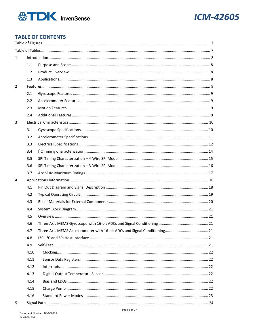
ICM-42605 2 5 3 TABLE OF CONTENTS Table of Figures ............................................................................................................................................................... 7 Table of Tables ................................................................................................................................................................ 7 Introduction ......................................................................................................................................................... 8 1 Purpose and Scope .................................................................................................................................... 8 1.1 1.2 Product Overview...................................................................................................................................... 8 1.3 Applications ............................................................................................................................................... 8 Features ............................................................................................................................................................... 9 2.1 Gyroscope Features .................................................................................................................................. 9 2.2 Accelerometer Features ............................................................................................................................ 9 2.3 Motion Features ........................................................................................................................................ 9 2.4 Additional Features ................................................................................................................................... 9 Electrical Characteristics .................................................................................................................................... 10 3.1 Gyroscope Specifications ........................................................................................................................ 10 3.2 Accelerometer Specifications .................................................................................................................. 11 Electrical Specifications ........................................................................................................................... 12 3.3 I2C Timing Characterization ..................................................................................................................... 14 3.4 3.5 SPI Timing Characterization – 4-Wire SPI Mode ..................................................................................... 15 SPI Timing Characterization – 3-Wire SPI Mode ..................................................................................... 16 3.6 3.7 Absolute Maximum Ratings .................................................................................................................... 17 Applications Information ................................................................................................................................... 18 Pin Out Diagram and Signal Description ................................................................................................. 18 4.1 Typical Operating Circuit ......................................................................................................................... 19 4.2 4.3 Bill of Materials for External Components .............................................................................................. 20 4.4 System Block Diagram ............................................................................................................................. 21 4.5 Overview ................................................................................................................................................. 21 4.6 Three-Axis MEMS Gyroscope with 16-bit ADCs and Signal Conditioning ............................................... 21 Three-Axis MEMS Accelerometer with 16-bit ADCs and Signal Conditioning ......................................... 21 4.7 I3C, I2C and SPI Host Interface ................................................................................................................ 21 4.8 4.9 Self-Test .................................................................................................................................................. 21 Clocking ............................................................................................................................................... 22 4.10 4.11 Sensor Data Registers ......................................................................................................................... 22 Interrupts ............................................................................................................................................ 22 4.12 Digital-Output Temperature Sensor ................................................................................................... 22 4.13 4.14 Bias and LDOs ..................................................................................................................................... 22 Charge Pump ...................................................................................................................................... 22 4.15 4.16 Standard Power Modes ...................................................................................................................... 23 Signal Path ......................................................................................................................................................... 24 4 Document Number: DS-000228 Revision: 0.4 Page 2 of 97
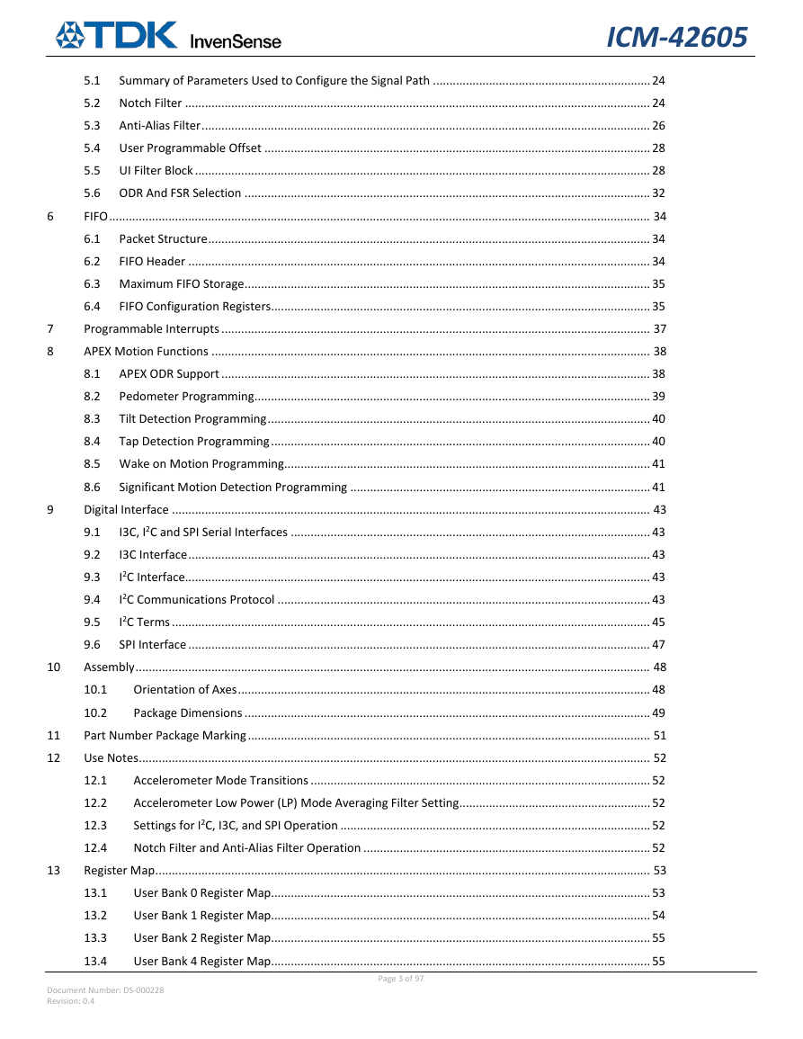
6 7 8 9 10 11 12 13 ICM-42605 5.1 Summary of Parameters Used to Configure the Signal Path .................................................................. 24 5.2 Notch Filter ............................................................................................................................................. 24 5.3 Anti-Alias Filter ........................................................................................................................................ 26 5.4 User Programmable Offset ..................................................................................................................... 28 5.5 UI Filter Block .......................................................................................................................................... 28 5.6 ODR And FSR Selection ........................................................................................................................... 32 FIFO .................................................................................................................................................................... 34 6.1 Packet Structure ...................................................................................................................................... 34 6.2 FIFO Header ............................................................................................................................................ 34 6.3 Maximum FIFO Storage ........................................................................................................................... 35 6.4 FIFO Configuration Registers ................................................................................................................... 35 Programmable Interrupts .................................................................................................................................. 37 APEX Motion Functions ..................................................................................................................................... 38 8.1 APEX ODR Support .................................................................................................................................. 38 Pedometer Programming ........................................................................................................................ 39 8.2 8.3 Tilt Detection Programming .................................................................................................................... 40 8.4 Tap Detection Programming ................................................................................................................... 40 8.5 Wake on Motion Programming ............................................................................................................... 41 8.6 Significant Motion Detection Programming ........................................................................................... 41 Digital Interface ................................................................................................................................................. 43 I3C, I2C and SPI Serial Interfaces ............................................................................................................. 43 9.1 9.2 I3C Interface ............................................................................................................................................ 43 I2C Interface ............................................................................................................................................. 43 9.3 I2C Communications Protocol ................................................................................................................. 43 9.4 9.5 I2C Terms ................................................................................................................................................. 45 9.6 SPI Interface ............................................................................................................................................ 47 Assembly ............................................................................................................................................................ 48 10.1 Orientation of Axes ............................................................................................................................. 48 10.2 Package Dimensions ........................................................................................................................... 49 Part Number Package Marking .......................................................................................................................... 51 Use Notes ........................................................................................................................................................... 52 Accelerometer Mode Transitions ....................................................................................................... 52 12.1 Accelerometer Low Power (LP) Mode Averaging Filter Setting .......................................................... 52 12.2 12.3 Settings for I2C, I3C, and SPI Operation .............................................................................................. 52 12.4 Notch Filter and Anti-Alias Filter Operation ....................................................................................... 52 Register Map ...................................................................................................................................................... 53 13.1 User Bank 0 Register Map................................................................................................................... 53 User Bank 1 Register Map................................................................................................................... 54 13.2 User Bank 2 Register Map................................................................................................................... 55 13.3 13.4 User Bank 4 Register Map................................................................................................................... 55 Document Number: DS-000228 Revision: 0.4 Page 3 of 97
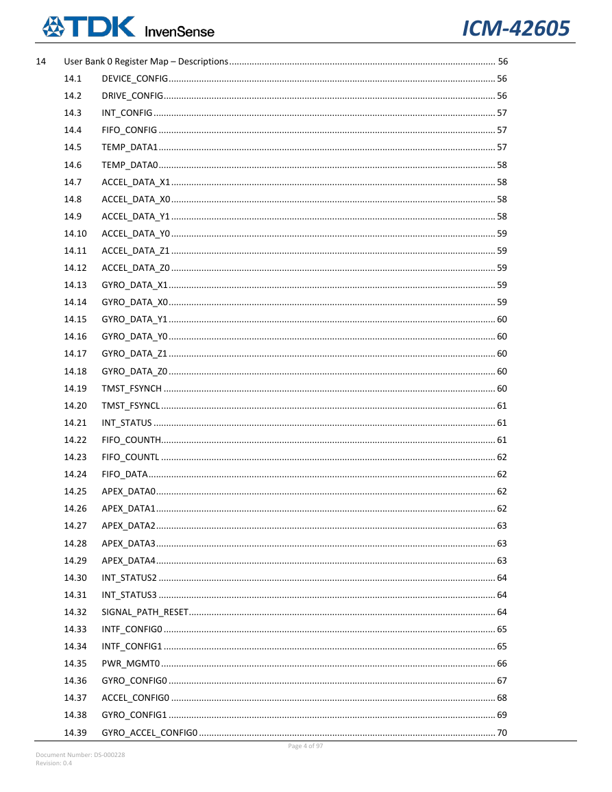
14 ICM-42605 User Bank 0 Register Map – Descriptions .......................................................................................................... 56 14.1 DEVICE_CONFIG .................................................................................................................................. 56 DRIVE_CONFIG .................................................................................................................................... 56 14.2 INT_CONFIG ........................................................................................................................................ 57 14.3 14.4 FIFO_CONFIG ...................................................................................................................................... 57 TEMP_DATA1 ...................................................................................................................................... 57 14.5 TEMP_DATA0 ...................................................................................................................................... 58 14.6 14.7 ACCEL_DATA_X1 ................................................................................................................................. 58 ACCEL_DATA_X0 ................................................................................................................................. 58 14.8 ACCEL_DATA_Y1 ................................................................................................................................. 58 14.9 14.10 ACCEL_DATA_Y0 ................................................................................................................................. 59 ACCEL_DATA_Z1 ................................................................................................................................. 59 14.11 ACCEL_DATA_Z0 ................................................................................................................................. 59 14.12 14.13 GYRO_DATA_X1 .................................................................................................................................. 59 GYRO_DATA_X0 .................................................................................................................................. 59 14.14 14.15 GYRO_DATA_Y1 .................................................................................................................................. 60 GYRO_DATA_Y0 .................................................................................................................................. 60 14.16 GYRO_DATA_Z1 .................................................................................................................................. 60 14.17 14.18 GYRO_DATA_Z0 .................................................................................................................................. 60 TMST_FSYNCH .................................................................................................................................... 60 14.19 TMST_FSYNCL ..................................................................................................................................... 61 14.20 14.21 INT_STATUS ........................................................................................................................................ 61 FIFO_COUNTH ..................................................................................................................................... 61 14.22 FIFO_COUNTL ..................................................................................................................................... 62 14.23 14.24 FIFO_DATA .......................................................................................................................................... 62 APEX_DATA0 ....................................................................................................................................... 62 14.25 APEX_DATA1 ....................................................................................................................................... 62 14.26 14.27 APEX_DATA2 ....................................................................................................................................... 63 APEX_DATA3 ....................................................................................................................................... 63 14.28 APEX_DATA4 ....................................................................................................................................... 63 14.29 14.30 INT_STATUS2 ...................................................................................................................................... 64 INT_STATUS3 ...................................................................................................................................... 64 14.31 SIGNAL_PATH_RESET .......................................................................................................................... 64 14.32 14.33 INTF_CONFIG0 .................................................................................................................................... 65 INTF_CONFIG1 .................................................................................................................................... 65 14.34 PWR_MGMT0 ..................................................................................................................................... 66 14.35 14.36 GYRO_CONFIG0 .................................................................................................................................. 67 ACCEL_CONFIG0 ................................................................................................................................. 68 14.37 GYRO_CONFIG1 .................................................................................................................................. 69 14.38 14.39 GYRO_ACCEL_CONFIG0 ...................................................................................................................... 70 Document Number: DS-000228 Revision: 0.4 Page 4 of 97
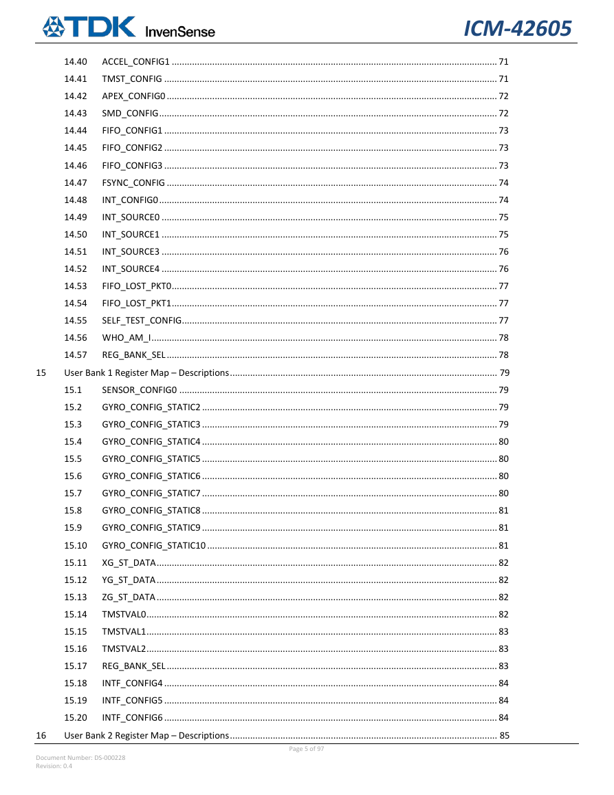
ICM-42605 ACCEL_CONFIG1 ................................................................................................................................. 71 14.40 TMST_CONFIG .................................................................................................................................... 71 14.41 APEX_CONFIG0 ................................................................................................................................... 72 14.42 SMD_CONFIG ...................................................................................................................................... 72 14.43 FIFO_CONFIG1 .................................................................................................................................... 73 14.44 FIFO_CONFIG2 .................................................................................................................................... 73 14.45 FIFO_CONFIG3 .................................................................................................................................... 73 14.46 FSYNC_CONFIG ................................................................................................................................... 74 14.47 INT_CONFIG0 ...................................................................................................................................... 74 14.48 INT_SOURCE0 ..................................................................................................................................... 75 14.49 INT_SOURCE1 ..................................................................................................................................... 75 14.50 INT_SOURCE3 ..................................................................................................................................... 76 14.51 INT_SOURCE4 ..................................................................................................................................... 76 14.52 FIFO_LOST_PKT0 ................................................................................................................................. 77 14.53 FIFO_LOST_PKT1 ................................................................................................................................. 77 14.54 SELF_TEST_CONFIG ............................................................................................................................. 77 14.55 14.56 WHO_AM_I ......................................................................................................................................... 78 14.57 REG_BANK_SEL ................................................................................................................................... 78 User Bank 1 Register Map – Descriptions .......................................................................................................... 79 SENSOR_CONFIG0 .............................................................................................................................. 79 15.1 GYRO_CONFIG_STATIC2 ..................................................................................................................... 79 15.2 15.3 GYRO_CONFIG_STATIC3 ..................................................................................................................... 79 GYRO_CONFIG_STATIC4 ..................................................................................................................... 80 15.4 GYRO_CONFIG_STATIC5 ..................................................................................................................... 80 15.5 15.6 GYRO_CONFIG_STATIC6 ..................................................................................................................... 80 GYRO_CONFIG_STATIC7 ..................................................................................................................... 80 15.7 GYRO_CONFIG_STATIC8 ..................................................................................................................... 81 15.8 15.9 GYRO_CONFIG_STATIC9 ..................................................................................................................... 81 GYRO_CONFIG_STATIC10 ................................................................................................................... 81 15.10 XG_ST_DATA ....................................................................................................................................... 82 15.11 15.12 YG_ST_DATA ....................................................................................................................................... 82 ZG_ST_DATA ....................................................................................................................................... 82 15.13 TMSTVAL0 ........................................................................................................................................... 82 15.14 15.15 TMSTVAL1 ........................................................................................................................................... 83 TMSTVAL2 ........................................................................................................................................... 83 15.16 REG_BANK_SEL ................................................................................................................................... 83 15.17 15.18 INTF_CONFIG4 .................................................................................................................................... 84 INTF_CONFIG5 .................................................................................................................................... 84 15.19 15.20 INTF_CONFIG6 .................................................................................................................................... 84 User Bank 2 Register Map – Descriptions .......................................................................................................... 85 15 16 Document Number: DS-000228 Revision: 0.4 Page 5 of 97
ICM-42605 ACCEL_CONFIG_STATIC2 .................................................................................................................... 85 16.1 ACCEL_CONFIG_STATIC3 .................................................................................................................... 85 16.2 ACCEL_CONFIG_STATIC4 .................................................................................................................... 85 16.3 XA_ST_DATA ....................................................................................................................................... 85 16.4 YA_ST_DATA ....................................................................................................................................... 86 16.5 ZA_ST_DATA ....................................................................................................................................... 86 16.6 16.7 REG_BANK_SEL ................................................................................................................................... 86 User Bank 4 Register Map – Descriptions .......................................................................................................... 87 APEX_CONFIG1 ................................................................................................................................... 87 17.1 APEX_CONFIG2 ................................................................................................................................... 87 17.2 17.3 APEX_CONFIG3 ................................................................................................................................... 88 APEX_CONFIG4 ................................................................................................................................... 88 17.4 APEX_CONFIG7 ................................................................................................................................... 89 17.5 17.6 APEX_CONFIG8 ................................................................................................................................... 89 ACCEL_WOM_X_THR .......................................................................................................................... 89 17.7 17.8 ACCEL_WOM_Y_THR .......................................................................................................................... 89 ACCEL_WOM_Z_THR .......................................................................................................................... 90 17.9 INT_SOURCE6 ..................................................................................................................................... 90 17.10 17.11 INT_SOURCE7 ..................................................................................................................................... 90 INT_SOURCE8 ..................................................................................................................................... 91 17.12 INT_SOURCE9 ..................................................................................................................................... 91 17.13 17.14 INT_SOURCE10 ................................................................................................................................... 92 17.15 REG_BANK_SEL ................................................................................................................................... 92 17.16 OFFSET_USER0 .................................................................................................................................... 92 17.17 OFFSET_USER1 .................................................................................................................................... 93 17.18 OFFSET_USER2 .................................................................................................................................... 93 17.19 OFFSET_USER3 .................................................................................................................................... 93 17.20 OFFSET_USER4 .................................................................................................................................... 93 17.21 OFFSET_USER5 .................................................................................................................................... 94 17.22 OFFSET_USER6 .................................................................................................................................... 94 17.23 OFFSET_USER7 .................................................................................................................................... 94 17.24 OFFSET_USER8 .................................................................................................................................... 94 Reference ........................................................................................................................................................... 95 Document Information ...................................................................................................................................... 96 Revision History .................................................................................................................................. 96 19.1 17 18 19 Document Number: DS-000228 Revision: 0.4 Page 6 of 97
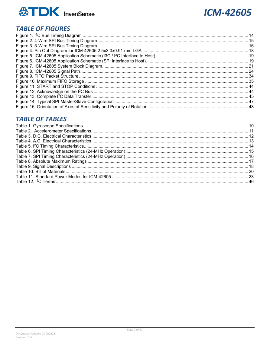
ICM-42605 TABLE OF FIGURES Figure 1. I2C Bus Timing Diagram ........................................................................................................................................ 14 Figure 2. 4-Wire SPI Bus Timing Diagram ............................................................................................................................ 15 Figure 3. 3-Wire SPI Bus Timing Diagram ............................................................................................................................ 16 Figure 4. Pin Out Diagram for ICM-42605 2.5x3.0x0.91 mm LGA ....................................................................................... 18 Figure 5. ICM-42605 Application Schematic (I3C / I2C Interface to Host) ............................................................................ 19 Figure 6. ICM-42605 Application Schematic (SPI Interface to Host) .................................................................................... 19 Figure 7. ICM-42605 System Block Diagram ........................................................................................................................ 21 Figure 8. ICM-42605 Signal Path .......................................................................................................................................... 24 Figure 9. FIFO Packet Structure ........................................................................................................................................... 34 Figure 10. Maximum FIFO Storage ...................................................................................................................................... 35 Figure 11. START and STOP Conditions ............................................................................................................................. 44 Figure 12. Acknowledge on the I2C Bus ............................................................................................................................... 44 Figure 13. Complete I2C Data Transfer ................................................................................................................................. 45 Figure 14. Typical SPI Master/Slave Configuration .............................................................................................................. 47 Figure 15. Orientation of Axes of Sensitivity and Polarity of Rotation .................................................................................. 48 TABLE OF TABLES Table 1. Gyroscope Specifications ....................................................................................................................................... 10 Table 2. Accelerometer Specifications ................................................................................................................................. 11 Table 3. D.C. Electrical Characteristics ................................................................................................................................ 12 Table 4. A.C. Electrical Characteristics ................................................................................................................................. 13 Table 5. I2C Timing Characteristics ....................................................................................................................................... 14 Table 6. SPI Timing Characteristics (24-MHz Operation) ..................................................................................................... 15 Table 7. SPI Timing Characteristics (24-MHz Operation) ..................................................................................................... 16 Table 8. Absolute Maximum Ratings .................................................................................................................................... 17 Table 9. Signal Descriptions ................................................................................................................................................. 18 Table 10. Bill of Materials ...................................................................................................................................................... 20 Table 11. Standard Power Modes for ICM-42605 ................................................................................................................ 23 Table 12. I2C Terms .............................................................................................................................................................. 46 Document Number: DS-000228 Revision: 0.4 Page 7 of 97
ICM-42605 INTRODUCTION 1 1.1 PURPOSE AND SCOPE This document is a product specification, providing a description, specifications, and design related information on the ICM-42605 Single-Interface MotionTracking device. The device is housed in a small 2.5x3x0.91 mm 14-pin LGA package. 1.2 PRODUCT OVERVIEW The ICM-42605 is a 6-axis MotionTracking device that combines a 3-axis gyroscope, and a 3-axis accelerometer in a small 2.5x3x0.91 mm (14-pin LGA) package. It also features a 2K-byte FIFO that can lower the traffic on the serial bus interface, and reduce power consumption by allowing the system processor to burst read sensor data and then go into a low-power mode. ICM-42605, with its 6-axis integration, enables manufacturers to eliminate the costly and complex selection, qualification, and system level integration of discrete devices, guaranteeing optimal motion performance for consumers. The gyroscope supports eight independently programmable full-scale range settings from ±15.625dps to ±2000dps, and the accelerometer supports four independently programmable full-scale range settings from ±2g to ±16g. Other industry-leading features include on-chip 16-bit ADCs, programmable digital filters, an embedded temperature sensor, and programmable interrupts. The device features I3C, I2C and SPI serial interfaces, and VDD operating range of 1.71 V to 3.6 V. The host interface can be configured to support I3C slave, I2C slave, or SPI slave modes. The I3C interface supports speeds up to 12.5MHz (data rates up to 12.5Mbps in SDR mode, 25Mbps in DDR mode), the I2C interface supports speeds up to 1 MHz, and the SPI interface supports speeds up to 24 MHz. By leveraging its patented and volume-proven CMOS-MEMS fabrication platform, which integrates MEMS wafers with companion CMOS electronics through wafer-level bonding, InvenSense has driven the package size down to a footprint and thickness of 2.5x3x0.91 mm (14-pin LGA), to provide a very small yet high performance low cost package. The device provides high robustness by supporting 20,000g shock reliability. 1.3 APPLICATIONS • Smartphones and Tablets • Head Mounted Displays • Wearable Sensors Document Number: DS-000228 Revision: 0.4 Page 8 of 97
分享到:
收藏