TMS320C6455/C6454 DSP DDR2 Memory Controller
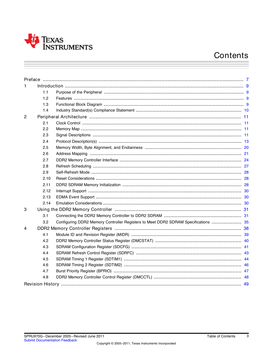
Table of Contents
Preface
1 Introduction
1.1 Purpose of the Peripheral
1.2 Features
1.3 Functional Block Diagram
1.4 Industry Standard(s) Compliance Statement
2 Peripheral Architecture
2.1 Clock Control
2.2 Memory Map
2.3 Signal Descriptions
2.4 Protocol Description(s)
2.4.1 Mode Register Set (MRS and EMRS)
2.4.2 Refresh Mode
2.4.3 Activation (ACTV)
2.4.4 Deactivation (DCAB and DEAC)
2.4.5 READ Command
2.4.6 Write (WRT) Command
2.5 Memory Width, Byte Alignment, and Endianness
2.6 Address Mapping
2.7 DDR2 Memory Controller Interface
2.7.1 Command Ordering and Scheduling, Advanced Concept
2.7.2 Command Starvation
2.7.3 Possible Race Condition
2.8 Refresh Scheduling
2.9 Self-Refresh Mode
2.10 Reset Considerations
2.11 DDR2 SDRAM Memory Initialization
2.11.1 DDR2 SDRAM Device Mode Register Configuration Values
2.11.2 DDR2 SDRAM Initialization After Reset
2.11.3 DDR2 SDRAM Initialization After Register Configuration
2.12 Interrupt Support
2.13 EDMA Event Support
2.14 Emulation Considerations
3 Using the DDR2 Memory Controller
3.1 Connecting the DDR2 Memory Controller to DDR2 SDRAM
3.2 Configuring DDR2 Memory Controller Registers to Meet DDR2 SDRAM Specifications
3.2.1 Programming the SDRAM Configuration Register (SDCFG)
3.2.2 Programming the SDRAM Refresh Control Register (SDRFC)
3.2.3 Configuring SDRAM Timing Registers (SDTIM1 and SDTIM2)
3.2.4 Configuring the DDR2 Memory Controller Control Register (DMCCTL)
4 DDR2 Memory Controller Registers
4.1 Module ID and Revision Register (MIDR)
4.2 DDR2 Memory Controller Status Register (DMCSTAT)
4.3 SDRAM Configuration Register (SDCFG)
4.4 SDRAM Refresh Control Register (SDRFC)
4.5 SDRAM Timing 1 Register (SDTIM1)
4.6 SDRAM Timing 2 Register (SDTIM2)
4.7 Burst Priority Register (BPRIO)
4.8 DDR2 Memory Controller Control Register (DMCCTL)
Revision History


 2023年江西萍乡中考道德与法治真题及答案.doc
 2012年重庆南川中考生物真题及答案.doc
 2013年江西师范大学地理学综合及文艺理论基础考研真题.doc
 2020年四川甘孜小升初语文真题及答案I卷.doc
 2020年注册岩土工程师专业基础考试真题及答案.doc
 2023-2024学年福建省厦门市九年级上学期数学月考试题及答案.doc
 2021-2022学年辽宁省沈阳市大东区九年级上学期语文期末试题及答案.doc
 2022-2023学年北京东城区初三第一学期物理期末试卷及答案.doc
 2018上半年江西教师资格初中地理学科知识与教学能力真题及答案.doc
 2012年河北国家公务员申论考试真题及答案-省级.doc
 2020-2021学年江苏省扬州市江都区邵樊片九年级上学期数学第一次质量检测试题及答案.doc
 2022下半年黑龙江教师资格证中学综合素质真题及答案.doc