Drew Technologies, Inc.
SAE J2534
API
REFERENCE
Copyright 2003 Drew Technologies, Inc.
i
�
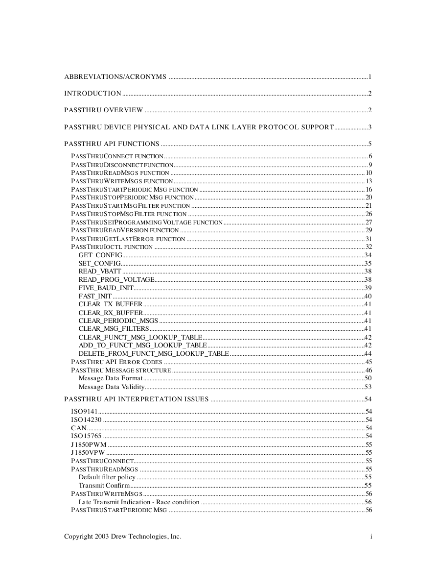
ABBREVIATIONS/ACRONYMS ............................................................................................................................1
INTRODUCTION.........................................................................................................................................................2
PASSTHRU OVERVIEW ...........................................................................................................................................2
PASSTHRU DEVICE PHYSICAL AND DATA LINK LAYER PROTOCOL SUPPORT.....................3
PASSTHRU API FUNCTIONS .................................................................................................................................5
PASSTHRUCONNECT FUNCTION............................................................................................................................... 6
PASSTHRUDISCONNECT FUNCTION......................................................................................................................... 9
PASSTHRUREADMSGS FUNCTION ......................................................................................................................... 10
PASSTHRUWRITEMSGS FUNCTION....................................................................................................................... 13
PASSTHRUSTARTPERIODIC MSG FUNCTION ....................................................................................................... 16
PASSTHRUSTOPPERIODICMSG FUNCTION.......................................................................................................... 20
PASSTHRUSTARTMSGFILTER FUNCTION ............................................................................................................ 21
PASSTHRUSTOPMSGFILTER FUNCTION .............................................................................................................. 26
PASSTHRUSETPROGRAMMINGVOLTAGE FUNCTION........................................................................................ 27
PASSTHRUREADVERSION FUNCTION ................................................................................................................... 29
PASSTHRUGETLASTERROR FUNCTION ............................................................................................................... 31
PASSTHRUIOCTL FUNCTION ................................................................................................................................... 32
GET_CONFIG.......................................................................................................................................................34
SET_CONFIG........................................................................................................................................................35
READ_VBATT .......................................................................................................................................................38
READ_PROG_VOLTAGE...................................................................................................................................38
FIVE_BAUD_INIT................................................................................................................................................39
FAST_INIT .............................................................................................................................................................40
CLEAR_TX_BUFFER..........................................................................................................................................41
CLEAR_RX_BUFFER..........................................................................................................................................41
CLEAR_PERIODIC_MSGS ................................................................................................................................41
CLEAR_MSG_FILTERS......................................................................................................................................41
CLEAR_FUNCT_MSG_LOOKUP_TABLE.....................................................................................................42
ADD_TO_FUNCT_MSG_LOOKUP_TABLE..................................................................................................42
DELETE_FROM_FUNCT_MSG_LOOKUP_TABLE....................................................................................44
PASSTHRU API ERROR CODES ............................................................................................................................. 45
PASSTHRU MESSAGE STRUCTURE........................................................................................................................ 46
Message Data Format..........................................................................................................................................50
Message Data Validity.........................................................................................................................................53
PASSTHRU API INTERPRETATION ISSUES ................................................................................................54
ISO9141...................................................................................................................................................................... 54
ISO14230 ................................................................................................................................................................... 54
CAN............................................................................................................................................................................. 54
ISO15765 ................................................................................................................................................................... 54
J1850PWM................................................................................................................................................................ 55
J1850VPW................................................................................................................................................................. 55
PASSTHRUCONNECT................................................................................................................................................ 55
PASSTHRUREADMSGS ............................................................................................................................................ 55
Default filter policy ..............................................................................................................................................55
Transmit Confirm..................................................................................................................................................55
PASSTHRUWRITEMSGS.......................................................................................................................................... 56
Late Transmit Indication - Race condition ......................................................................................................56
PASSTHRUSTARTPERIODIC MSG .......................................................................................................................... 56
Copyright 2003 Drew Technologies, Inc.
i
�
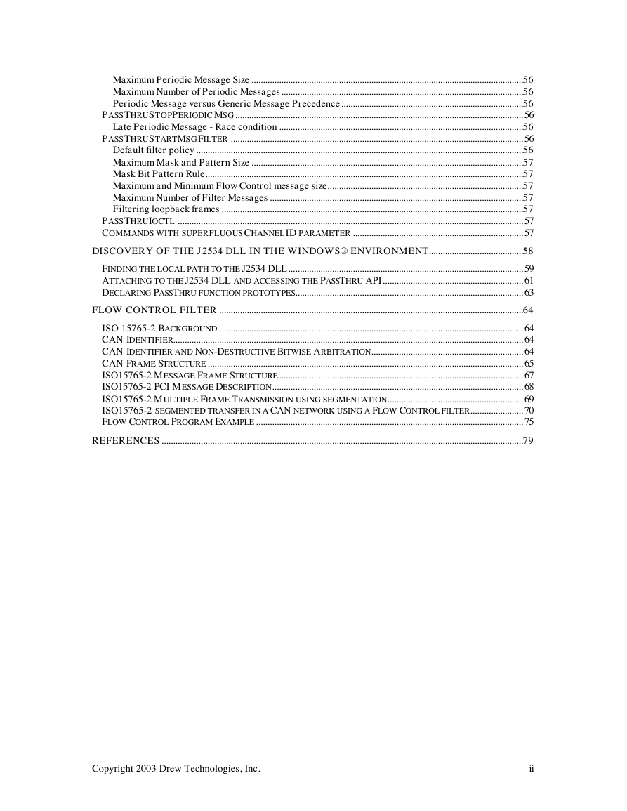
Maximum Periodic Message Size ......................................................................................................................56
Maximum Number of Periodic Messages.........................................................................................................56
Periodic Message versus Generic Message Precedence...............................................................................56
PASSTHRUSTOPPERIODICMSG............................................................................................................................. 56
Late Periodic Message - Race condition ..........................................................................................................56
PASSTHRUSTARTMSGFILTER ............................................................................................................................... 56
Default filter policy ..............................................................................................................................................56
Maximum Mask and Pattern Size ......................................................................................................................57
Mask Bit Pattern Rule..........................................................................................................................................57
Maximum and Minimum Flow Control message size.....................................................................................57
Maximum Number of Filter Messages ..............................................................................................................57
Filtering loopback frames ...................................................................................................................................57
PASSTHRUIOCTL ...................................................................................................................................................... 57
COMMANDS WITH SUPERFLUOUS CHANNELID PARAMETER .......................................................................... 57
DISCOVERY OF THE J2534 DLL IN THE WINDOWS® ENVIRONMENT.........................................58
FINDING THE LOCAL PATH TO THE J2534 DLL...................................................................................................... 59
ATTACHING TO THE J2534 DLL AND ACCESSING THE PASSTHRU API............................................................. 61
DECLARING PASSTHRU FUNCTION PROTOTYPES................................................................................................... 63
FLOW CONTROL FILTER ....................................................................................................................................64
ISO 15765-2 BACKGROUND .................................................................................................................................... 64
CAN IDENTIFIER........................................................................................................................................................ 64
CAN IDENTIFIER AND NON-DESTRUCTIVE BITWISE ARBITRATION.................................................................. 64
CAN FRAME STRUCTURE ......................................................................................................................................... 65
ISO15765-2 MESSAGE FRAME STRUCTURE.......................................................................................................... 67
ISO15765-2 PCI MESSAGE DESCRIPTION............................................................................................................. 68
ISO15765-2 MULTIPLE FRAME TRANSMISSION USING SEGMENTATION........................................................... 69
ISO15765-2 SEGMENTED TRANSFER IN A CAN NETWORK USING A FLOW CONTROL FILTER....................... 70
FLOW CONTROL PROGRAM EXAMPLE .................................................................................................................... 75
REFERENCES .............................................................................................................................................................79
Copyright 2003 Drew Technologies, Inc.
ii
�
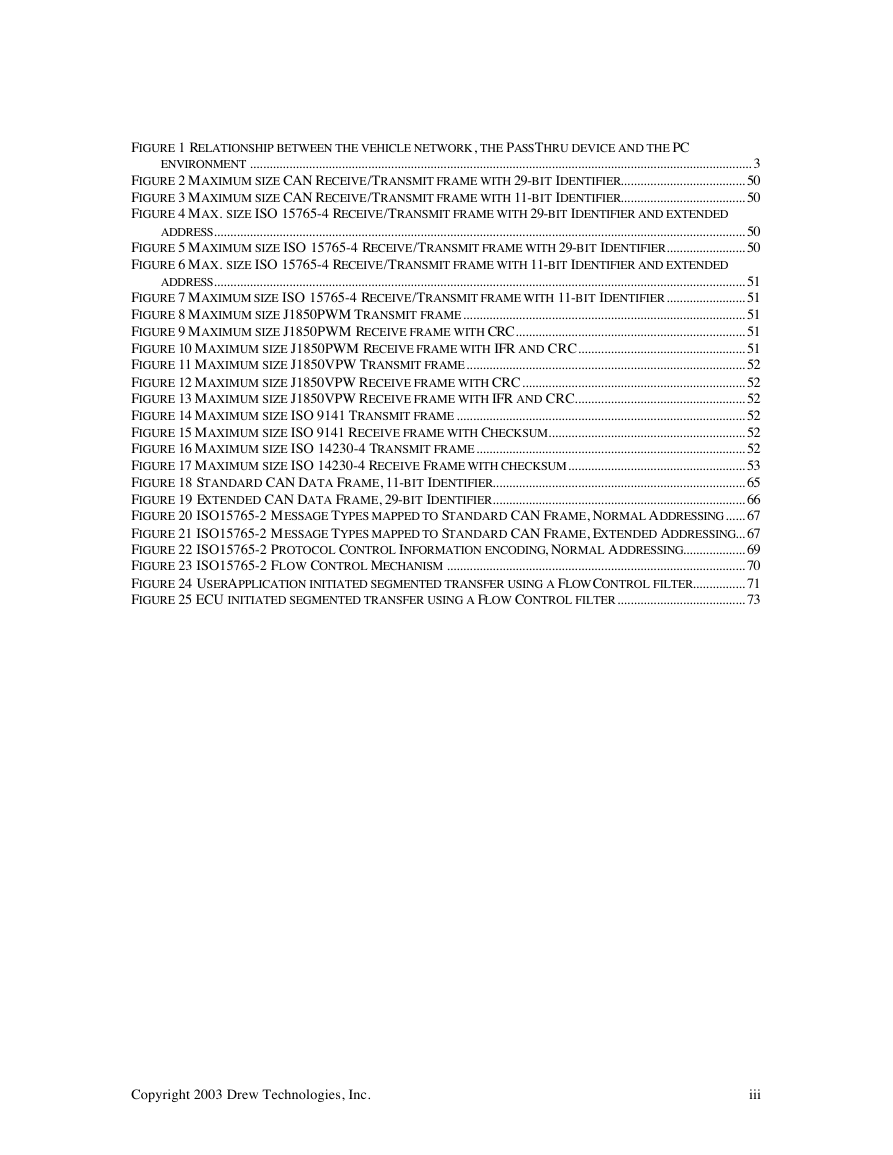
FIGURE 1 RELATIONSHIP BETWEEN THE VEHICLE NETWORK, THE PASSTHRU DEVICE AND THE PC
ENVIRONMENT ......................................................................................................................................................... 3
FIGURE 2 MAXIMUM SIZE CAN RECEIVE/TRANSMIT FRAME WITH 29-BIT IDENTIFIER...................................... 50
FIGURE 3 MAXIMUM SIZE CAN RECEIVE/TRANSMIT FRAME WITH 11-BIT IDENTIFIER...................................... 50
FIGURE 4 MAX. SIZE ISO 15765-4 RECEIVE/TRANSMIT FRAME WITH 29-BIT IDENTIFIER AND EXTENDED
ADDRESS.................................................................................................................................................................. 50
FIGURE 5 MAXIMUM SIZE ISO 15765-4 RECEIVE/TRANSMIT FRAME WITH 29-BIT IDENTIFIER........................ 50
FIGURE 6 MAX. SIZE ISO 15765-4 RECEIVE/TRANSMIT FRAME WITH 11-BIT IDENTIFIER AND EXTENDED
ADDRESS.................................................................................................................................................................. 51
FIGURE 7 MAXIMUM SIZE ISO 15765-4 RECEIVE/TRANSMIT FRAME WITH 11-BIT IDENTIFIER........................ 51
FIGURE 8 MAXIMUM SIZE J1850PWM TRANSMIT FRAME...................................................................................... 51
FIGURE 9 MAXIMUM SIZE J1850PWM RECEIVE FRAME WITH CRC...................................................................... 51
FIGURE 10 MAXIMUM SIZE J1850PWM RECEIVE FRAME WITH IFR AND CRC................................................... 51
FIGURE 11 MAXIMUM SIZE J1850VPW TRANSMIT FRAME..................................................................................... 52
FIGURE 12 MAXIMUM SIZE J1850VPW RECEIVE FRAME WITH CRC.................................................................... 52
FIGURE 13 MAXIMUM SIZE J1850VPW RECEIVE FRAME WITH IFR AND CRC.................................................... 52
FIGURE 14 MAXIMUM SIZE ISO 9141 TRANSMIT FRAME ........................................................................................ 52
FIGURE 15 MAXIMUM SIZE ISO 9141 RECEIVE FRAME WITH CHECKSUM............................................................ 52
FIGURE 16 MAXIMUM SIZE ISO 14230-4 TRANSMIT FRAME.................................................................................. 52
FIGURE 17 MAXIMUM SIZE ISO 14230-4 RECEIVE FRAME WITH CHECKSUM...................................................... 53
FIGURE 18 STANDARD CAN DATA FRAME, 11-BIT IDENTIFIER............................................................................. 65
FIGURE 19 EXTENDED CAN DATA FRAME, 29-BIT IDENTIFIER............................................................................. 66
FIGURE 20 ISO15765-2 MESSAGE TYPES MAPPED TO STANDARD CAN FRAME, NORMAL ADDRESSING...... 67
FIGURE 21 ISO15765-2 MESSAGE TYPES MAPPED TO STANDARD CAN FRAME, EXTENDED ADDRESSING... 67
FIGURE 22 ISO15765-2 PROTOCOL CONTROL INFORMATION ENCODING, NORMAL ADDRESSING................... 69
FIGURE 23 ISO15765-2 FLOW CONTROL MECHANISM ........................................................................................... 70
FIGURE 24 USERAPPLICATION INITIATED SEGMENTED TRANSFER USING A FLOWCONTROL FILTER................ 71
FIGURE 25 ECU INITIATED SEGMENTED TRANSFER USING A FLOW CONTROL FILTER....................................... 73
Copyright 2003 Drew Technologies, Inc.
iii
�
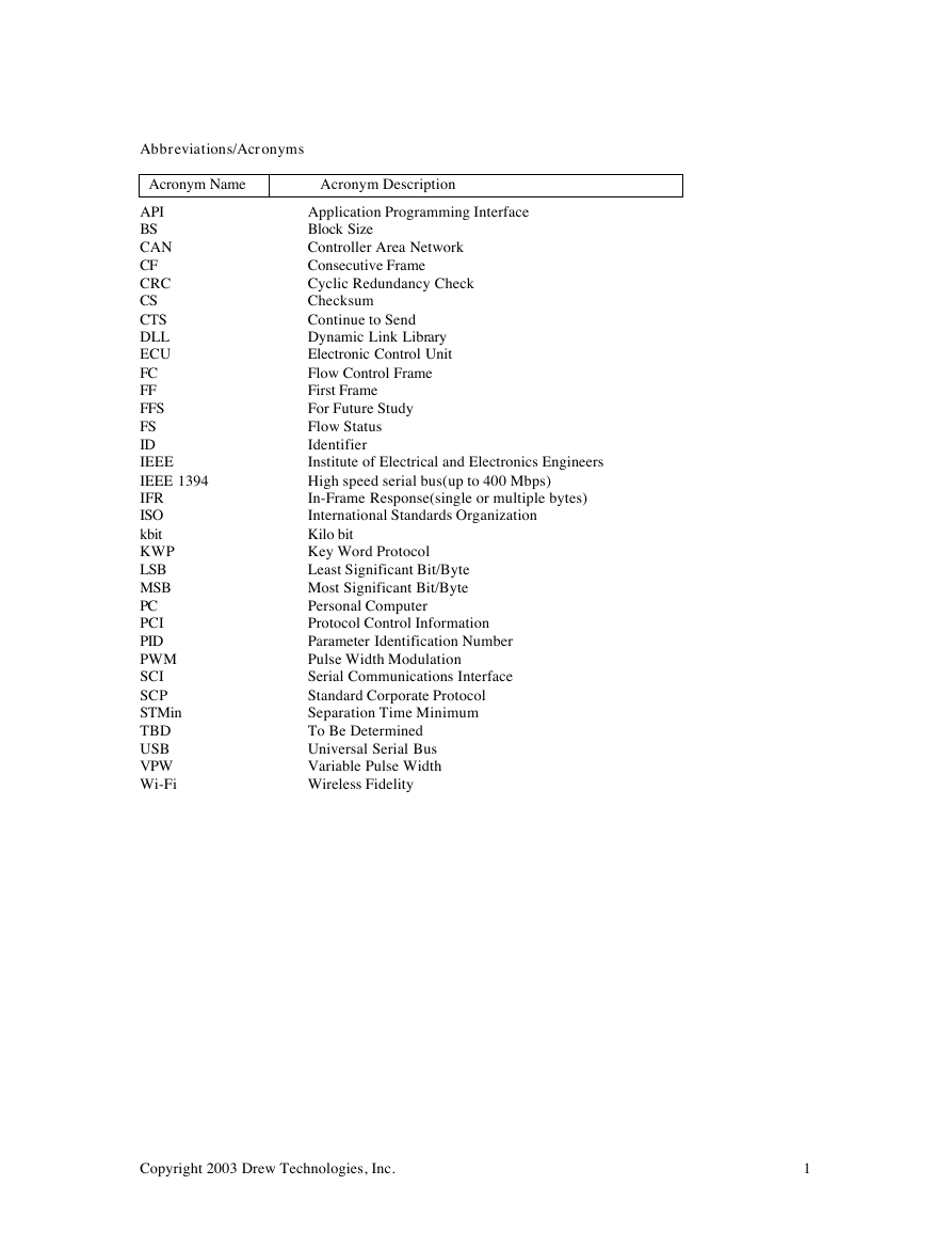
Abbreviations/Acronyms
Acronym Name
Acronym Description
API
BS
CAN
CF
CRC
CS
CTS
DLL
ECU
FC
FF
FFS
FS
ID
IEEE
IEEE 1394
IFR
ISO
kbit
KWP
LSB
MSB
PC
PCI
PID
PWM
SCI
SCP
STMin
TBD
USB
VPW
Wi-Fi
Application Programming Interface
Block Size
Controller Area Network
Consecutive Frame
Cyclic Redundancy Check
Checksum
Continue to Send
Dynamic Link Library
Electronic Control Unit
Flow Control Frame
First Frame
For Future Study
Flow Status
Identifier
Institute of Electrical and Electronics Engineers
High speed serial bus(up to 400 Mbps)
In-Frame Response(single or multiple bytes)
International Standards Organization
Kilo bit
Key Word Protocol
Least Significant Bit/Byte
Most Significant Bit/Byte
Personal Computer
Protocol Control Information
Parameter Identification Number
Pulse Width Modulation
Serial Communications Interface
Standard Corporate Protocol
Separation Time Minimum
To Be Determined
Universal Serial Bus
Variable Pulse Width
Wireless Fidelity
Copyright 2003 Drew Technologies, Inc.
1
�
Introduction
This paper describes a communication API that connects ECUs on a vehicle network to a PC based user
application running in a standard Windows® environment.
Using external reprogramming tools for updating ECU firmware and calibration settings is a growing trend.
Before the J2534 specification multiple hardware and software tools were necessary to reprogram vehicles
from different manufacturers. The “multiple tool” situation proved confusing and expensive for any
aftermarket business that repaired or customized vehicles from a wide array of international and/or
domestic manufacturers. In addition the U.S. Environmental Protection Agency(EPA) has developed
vehicle network requirements that all vehicle manufacturers must meet for the 2004 model year and
beyond. The EPA mandated compliance test suite(J1699) requires communicating with the vehicle network
through a scan tool device. Both private business demands and new governmental regulations have
provided the impetus for developing a hardware platform that is compatible with all vehicles.
The J2534 specification defines a hardware device that interfaces to the vehicle network and a PC based
software Application API that controls the hardware device. The PC based Application manages all aspects
of the ECU reprogramming process through the J2534 API. The hardware device is concerned with
providing physical and data link layer support for the specified J2534 protocols. This arrangement allows
the vehicle manufactures to restrict access to proprietary reprogramming algorithms and support files and
allows one hardware device to be used for programming all vehicles.
PassThru Overview
The PassThru User Application executes on a Windows® PC and contains the proprietary software steps
for reprogramming, calibrating and monitoring ECUs within the target vehicle network. The PassThru User
Application contains the GUI presented to the user/operator, parses the Windows® registry to locate and
dynamically link to the vendor’s PassThru J2534 API/DLL, provides access to proprietary downloadable
software and calibration files, maintains and enforces security policies to control user access and provides
vehicle specific programming algorithms for controlling the ECU reflashing process. The generic PC must
have a Win32® operating system installed(i.e. Windows® 95/98, Windows NT™, Windows® Millennium
Edition, Windows® 2000, Windows® XP, ….). Also the PC may need to have an Internet connection, as
some User Applications may be WEB based or require access to external WEB sites for obtaining the
flashable ECU files.
The User Application references J2534 API routines to control the PassThru device and control the
message flow between the PassThru device and the target vehicle’s ECUs. The PassThru device does not
interpret, modify or examine User Application messages destined for the vehicle network(except for
ISO15765-2 protocol). Its role is to provide physical layer connectivity for the required list of network
layer protocols and to take care of the data link layer formatting details for each network protocol. The
PassThru device allows network messages to flow seamlessly between the ECUs connected to the vehicle
network and the User Application running on the PC.
The PassThru device manufacturer supplies the hardware appliance and cable that connects to and
communicates with the vehicle network. The physical interface to the vehicle network is the SAE J1962
connector, which supports the various vehicle serial data protocols. The following network layer protocols
are supported:
ISO 9141
ISO 14230-4(KWP2000, Keyword Protocol)
SAE J1850 41.6 KBPS PWM(Pulse Width Modulation)
SAE J1850 10.4 KBPS VPW(Variable Pulse Width)
CAN(Controller Area Network, ISO 11898)
ISO 15765-4(CAN)
SAE J2610 DaimlerChrysler SCI(Serial Communications Interface)
Copyright 2003 Drew Technologies, Inc.
2
�
The PassThru device manufacturer also supplies the cable and any required specialized Comm Port drivers
that form the communication link to the PC. This communication link can be RS-232, USB, Ethernet,
IEEE1394 or Wi-Fi. The PassThru manufacturer also supplies the J2534 DLL, which is installed on the PC
and referenced by the User Application. In order to reduce programming complexity the J2534 DLL does
not support multi-threading so the User Application is restricted to a single thread design.
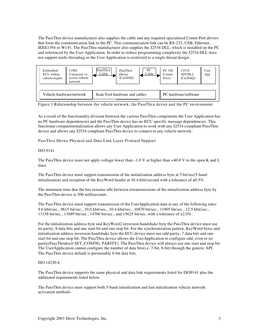
Embedded
ECU within
vehicle engine
J1962
Connector to
access vehicle
network
PassThru
Cable
PassThru
Device
(CarDAQ)
PC
Cable
PC OS
Comm
Ports
J2534
API/DLL
(CarDAQ)
User
App
Vehicle hardware/network
Scan Tool hardware and cables
PC hardware/software
Figure 1 Relationship between the vehicle network, the PassThru device and the PC environment
As a result of the functionality division between the various PassThru components the User Application has
no PC hardware dependencies and the PassThru device has no ECU specific message dependencies. This
functional compartmentalization allows any User Application to work with any J2534 compliant PassThru
device and allows any J2534 compliant PassThru device to connect to any vehicle network.
PassThru Device Physical and Data Link Layer Protocol Support
ISO 9141
The PassThru device must not apply voltage lower than –1.0 V or higher than +40.0 V to the open K and L
lines.
The PassThru device must support transmission of the initialization address byte at 5 bit/sec(5-baud
initialization) and reception of the KeyWord header at 10.4 kbit/second with a tolerance of ±0.5%.
The minimum time that the bus remains idle between retransmissions of the initialization address byte by
the PassThru device is 300 milliseconds.
The PassThru device must support transmission of the UserApplication data at any of the following rates:
9.6 kbit/sec., 9615 bit/sec., 10.0 kbit/sec., 10.4 kbit/sec., 10870 bit/sec., 11905 bit/sec., 12.5 kbit/sec.,
13158 bit/sec., 13889 bit/sec., 14706 bit/sec., and 15625 bit/sec. with a tolerance of ±2.0%.
For the initialization address byte and KeyWord2 inversion handshake byte the PassThru device must use
no parity, 8 data bits and one start bit and one stop bit. For the synchronization pattern, KeyWord bytes and
initialization address inversion handshake byte the ECU device must use odd parity, 7 data bits and one
start bit and one stop bit. The PassThru device allows the UserApplication to configure odd, even or no
parity(PassThruIoctl SET_CONFIG, PARITY). The PassThru device will always use one start and stop bit.
The UserApplication cannot configure the number of data bits(i.e. 7-bit, 8-bit) through the generic API.
The PassThru device default is presumably 8-bit data bits.
ISO 14230-4
The PassThru device supports the same physical and data link requirements listed for ISO9141 plus the
additional requirements listed below.
The PassThru device must support both 5-baud initialization and fast initialization vehicle network
activation methods.
Copyright 2003 Drew Technologies, Inc.
3
�
The PassThru device automatically sends TesterPresent messages to the ECUs after network initialization
to keep network communications active.
The PassThru device automatically handles the RequestCorrectlyReceived-ResponsePending(0x78) ECU
negative response by remaining in receive mode longer than the P2_MAX(maximum ECU response time)
time interval. The PassThru device may receive multiple RequestCorrectlyReceived-ResponsePending
responses until the ECU completes the request and either returns a positive or negative response(other than
0x78).
J1850PWM
The PassThru device supports two baud rates, 41.6 kbit/sec. for normal diagnostic operations and an 83.3
kbit/sec. for reprogramming.
The PassThru device must follow J1850PWM(SCP) physical layer requirements.
J1850VPW
The PassThru device supports two baud rates, 10.4 kbit/sec. for normal diagnostic operations and a 41.6
kbit/sec. for reprogramming. The PassThru device must accommodate receive and transmit frames up to
4,128 bytes in size.
CAN
The PassThru device supports sample point positioning at 80% ±2% and 68.5% ±2% of the nominal bit
rate.
The PassThru device supports two baud rates 250 kbit/second and 500 kbit/second.
The PassThru device does not provide support for a flow control mechanism and the UserApplication must
support any custom flow control mechanism.
ISO 15765-4
The PassThru device supports sample point positioning at 80% ±2% of the nominal bit rate.
The PassThru device supports two baud rates 250 kbit/second and 500 kbit/second. The PassThru device
support s both 11-bit and 29-bit Identifiers with or without extended addressing. The PassThru device
provides support for the ISO 15765-2 flow control mechanism.
SCI
Refer to J2610 DaimlerChrysler SCI for physical and data link layer details.
Copyright 2003 Drew Technologies, Inc.
4
�



 2023年江西萍乡中考道德与法治真题及答案.doc
 2012年重庆南川中考生物真题及答案.doc
 2013年江西师范大学地理学综合及文艺理论基础考研真题.doc
 2020年四川甘孜小升初语文真题及答案I卷.doc
 2020年注册岩土工程师专业基础考试真题及答案.doc
 2023-2024学年福建省厦门市九年级上学期数学月考试题及答案.doc
 2021-2022学年辽宁省沈阳市大东区九年级上学期语文期末试题及答案.doc
 2022-2023学年北京东城区初三第一学期物理期末试卷及答案.doc
 2018上半年江西教师资格初中地理学科知识与教学能力真题及答案.doc
 2012年河北国家公务员申论考试真题及答案-省级.doc
 2020-2021学年江苏省扬州市江都区邵樊片九年级上学期数学第一次质量检测试题及答案.doc
 2022下半年黑龙江教师资格证中学综合素质真题及答案.doc