Deskbook Release 4.0
�
The file "Deskbook Rel 4.0.pdf" is the latest version of the “Systems Engineering Best Practices with the Rational Solution for Systems and Software
Engineering Deskbook Release 4.0” (“Deskbook”), released July 2013.
The Deskbook is written for the practitioner. Screenshots, notes and best practice tips are added to the workflow descriptions. The brief introductions
are minimal rather than narrative. The Deskbook is not intended to replace IBM Rational Rhapsody training; it is intended to supplement it. It is
assumed that the reader is familiar with UML/SysML and the IBM Rational Rhapsody tool.
Permission to use, copy, and distribute, this Deskbook, is granted; provided, however, that the use, copy, and distribution of the Deskbook is made in
whole and not in part.
THIS DESKBOOK IS PROVIDED "AS IS." IBM MAKE NO REPRESENTATIONS OR WARRANTIES, EXPRESS OR IMPLIED, INCLUDING, BUT
NOT LIMITED TO, WARRANTIES OF MERCHANTABILITY, OR FITNESS FOR A PARTICULAR PURPOSE.
IBM WILL NOT BE LIABLE FOR ANY DIRECT, INDIRECT, SPECIAL, OR CONSEQUENTIAL DAMAGES ARISING OUT OF ANY USE OF THE
DESKBOOK OR THE PERFORMANCE OR IMPLEMENTATION OF THE CONTENTS OF THE DESKBOOK.
The directory "Deskbook Rel.4.0 Requirements and Models" contains the requirements specification for the Security System example and
snapshots of the models generated with Rhapsody.
Copyright IBM Corporation 2006, 2011
IBM Corporation
Software Group
Route 100
Somers, NY 10589
U.S.A.
Licensed Materials - Property of IBM Corporation
U.S. Government Users Restricted Rights: Use, duplication or disclosure restricted by GSA ADP Schedule Contract with IBM Corp.
IBM, the IBM logo, Rational, the Rational logo, Telelogic, the Telelogic logo and other IBM products and services are trademarks of the International
Business Machines Corporation, in the United States, other countries or both.
Other company, product, or service names may be trademarks or service marks of others.
The Rational Software home page on the Internet can be found at ibm.com/software/rational
The IBM home page on the Internet can be found at ibm.com
�
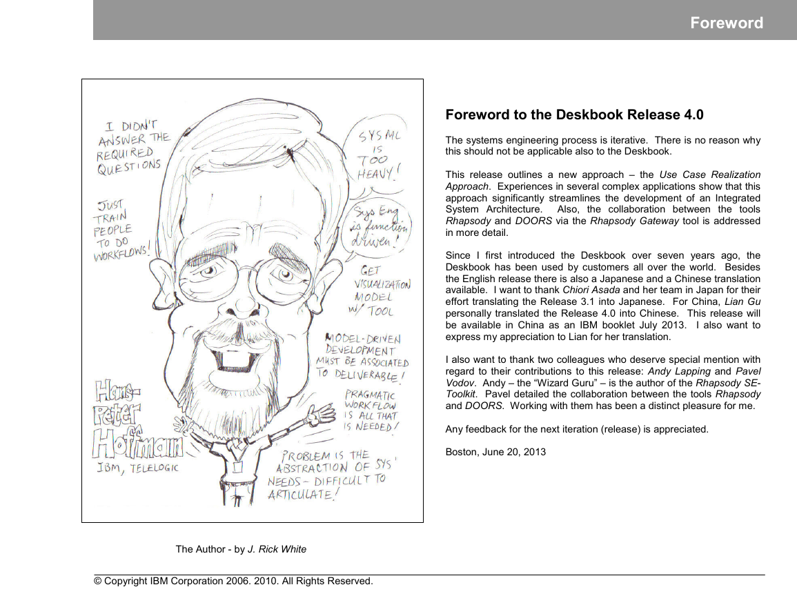
The Author - by J. Rick White
© Copyright IBM Corporation 2006. 2010. All Rights Reserved.
Foreword
Foreword to the Deskbook Release 4.0
The systems engineering process is iterative. There is no reason why
this should not be applicable also to the Deskbook.
This release outlines a new approach – the Use Case Realization
Approach. Experiences in several complex applications show that this
approach significantly streamlines the development of an Integrated
System Architecture. Also, the collaboration between the tools
Rhapsody and DOORS via the Rhapsody Gateway tool is addressed
in more detail.
Since I first introduced the Deskbook over seven years ago, the
Deskbook has been used by customers all over the world. Besides
the English release there is also a Japanese and a Chinese translation
available. I want to thank Chiori Asada and her team in Japan for their
effort translating the Release 3.1 into Japanese. For China, Lian Gu
personally translated the Release 4.0 into Chinese. This release will
be available in China as an IBM booklet July 2013. I also want to
express my appreciation to Lian for her translation.
I also want to thank two colleagues who deserve special mention with
regard to their contributions to this release: Andy Lapping and Pavel
Vodov. Andy – the “Wizard Guru” – is the author of the Rhapsody SE-
Toolkit. Pavel detailed the collaboration between the tools Rhapsody
and DOORS. Working with them has been a distinct pleasure for me.
Any feedback for the next iteration (release) is appreciated.
Boston, June 20, 2013
�
Table of Contents
Table of Contents
1
INTRODUCTION ......................................................................................................................................................................................................... 1
1.1 SCOPE ................................................................................................................................................................................................................... 1
1.2 DOCUMENT OVERVIEW............................................................................................................................................................................................ 1
2 FUNDAMENTALS OF HARMONY FOR SYSTEMS ENGINEERING ........................................................................................................................ 2
2.2.1
2.2.2
2.2.3
2.2.4
2.3.1
2.3.2
2.3.3
2.2.3.1
2.2.3.2
2.1 RATIONAL INTEGRATED SYSTEMS / EMBEDDED SOFTWARE DEVELOPMENT PROCESS HARMONY ................................................................................ 2
2.2 MODEL-BASED SYSTEMS ENGINEERING PROCESS.................................................................................................................................................... 4
Requirements Analysis.................................................................................................................................................................................. 5
System Functional Analysis .......................................................................................................................................................................... 6
Design Synthesis......................................................................................................................................................................................... 10
Architectural Analysis ........................................................................................................................................................................... 10
Architectural Design ............................................................................................................................................................................. 13
Systems Engineering Hand-Off................................................................................................................................................................... 17
2.3 ESSENTIAL SYSML ARTIFACTS OF MODEL-BASED SYSTEMS ENGINEERING.............................................................................................................. 18
Requirements Diagram ............................................................................................................................................................................... 19
Structure Diagrams...................................................................................................................................................................................... 19
Block Definition Diagram...................................................................................................................................................................... 19
Internal Block Diagram......................................................................................................................................................................... 19
Parametric Diagram ............................................................................................................................................................................. 21
Behavior Diagrams ...................................................................................................................................................................................... 21
Use Case Diagram ............................................................................................................................................................................... 22
Activity Diagram ................................................................................................................................................................................... 22
Sequence Diagram .............................................................................................................................................................................. 23
Statechart Diagram .............................................................................................................................................................................. 23
Artifact Relationships at the Requirements Analysis / System Functional Analysis Level.......................................................................... 24
2.4 SERVICE REQUEST-DRIVEN MODELING APPROACH ................................................................................................................................................ 25
2.3.3.1
2.3.3.2
2.3.3.3
2.3.3.4
2.3.2.1
2.3.2.2
2.3.2.3
2.3.4
3 RHAPSODY PROJECT STRUCTURE ..................................................................................................................................................................... 26
3.1 PROJECT STRUCTURE OVERVIEW .......................................................................................................................................................................... 26
3.2 REQUIREMENTS ANALYSIS PACKAGE ..................................................................................................................................................................... 27
3.3
FUNCTIONAL ANALYSIS PACKAGE .......................................................................................................................................................................... 28
3.4 DESIGN SYNTHESIS PACKAGE ............................................................................................................................................................................... 29
Architectural Analysis Package ................................................................................................................................................................... 29
Architectural Design Package ..................................................................................................................................................................... 30
3.5 SYSTEM-LEVEL DEFINITIONS ................................................................................................................................................................................. 31
3.4.1
3.4.2
4 CASE STUDY: SECURITY SYSTEM ....................................................................................................................................................................... 32
4.1 CASE STUDY WORKFLOW...................................................................................................................................................................................... 32
4.2 CREATION OF A HARMONY PROJECT STRUCTURE................................................................................................................................................... 33
Harmony for SE Deskbook | ii
© Copyright IBM Corporation 2006, 2010. All Rights Reserved.
�
Table of Contents
4.3.5.1
4.4.2
4.5.1
4.3.1
4.3.2
4.3.3
4.3.4
4.3.5
4.3.6
4.4.1
4.4.1.1
4.4.1.2
4.4.1.3
4.4.1.4
4.4.1.5
4.4.1.6
4.4.1.7
4.3 REQUIREMENTS ANALYSIS..................................................................................................................................................................................... 34
DOORS: Import of Stakeholder Requirements ........................................................................................................................................... 35
DOORS: Import of System Requirements................................................................................................................................................... 36
Linking System Requirements to Stakeholder Requirements..................................................................................................................... 38
DOORS -> Gateway -> Rhapsody: Import of System Requirements ......................................................................................................... 41
Definition of System-Level Use Cases ........................................................................................................................................................ 42
Linking Requirements to Use Cases.................................................................................................................................................... 43
Rhapsody -> Gateway -> DOORS: Export of Use Cases ........................................................................................................................... 46
4.4 SYSTEM FUNCTIONAL ANALYSIS............................................................................................................................................................................. 48
Uc1ControlEntry .......................................................................................................................................................................................... 49
Definition of Model Context .................................................................................................................................................................. 49
Definition of Functional Flow ................................................................................................................................................................ 52
Derivation of Black-Box Use Case Scenarios ...................................................................................................................................... 53
Definition of Ports and Interfaces ......................................................................................................................................................... 57
Definition of Use Case Behavior .......................................................................................................................................................... 58
Use Case Model Verification ................................................................................................................................................................ 60
Linking Model Properties to Requirements .......................................................................................................................................... 62
Uc2ControlExit............................................................................................................................................................................................. 64
Definition of Model Context .................................................................................................................................................................. 64
Definition of Functional Flow ................................................................................................................................................................ 64
Derivation of Black-Box Use Case Scenarios ...................................................................................................................................... 65
Definition of Ports and Interfaces ......................................................................................................................................................... 66
Definition of Use Case Behavior .......................................................................................................................................................... 66
Use Case Model Verification ................................................................................................................................................................ 67
Linking Model Properties to Requirements .......................................................................................................................................... 67
4.5 DESIGN SYNTHESIS............................................................................................................................................................................................... 68
Architectural Analysis (Trade-Off Analysis)................................................................................................................................................. 68
Definition of Key System Functions ..................................................................................................................................................... 69
Definition of Candidate Solutions ......................................................................................................................................................... 70
Definition of Assessment Criteria ......................................................................................................................................................... 71
Assigning Weights to Assessment Criteria .......................................................................................................................................... 72
Definition of a Utility Curve for each Criterion ...................................................................................................................................... 73
Assigning Measures of Effectiveness (MoE) to each Solution............................................................................................................. 74
Determination of Solution ..................................................................................................................................................................... 75
Documentation of the Solution in the ArchitecturalDesignPkg............................................................................................................. 77
Architectural Design .................................................................................................................................................................................... 78
Use Case Realization Uc1ControlEntry ............................................................................................................................................... 79
4.5.2.1.1 Update of the ArchitecturalDesignPkg ............................................................................................................................................. 79
4.5.2.1.2 Allocation of System Block Properies to Parts ................................................................................................................................. 80
4.5.2.1.2.1 Allocation of Operations to Parts ............................................................................................................................................... 80
4.5.2.1.2.2 Allocation of Attributes and Events to Parts .............................................................................................................................. 84
4.5.2.1.3 Derivation of White-Box Sequence Diagrams.................................................................................................................................. 85
4.5.2.1.4 Definition of Ports and Interfaces ..................................................................................................................................................... 88
4.5.1.1
4.5.1.2
4.5.1.3
4.5.1.4
4.5.1.5
4.5.1.6
4.5.1.7
4.5.1.8
4.4.2.1
4.4.2.2
4.4.2.3
4.4.2.4
4.4.2.5
4.4.2.6
4.4.2.7
4.5.2
4.5.2.1
© Copyright IBM Corporation 2006, 2010. All Rights Reserved.
Harmony for SE Deskbook | iii
�
Table of Contents
4.5.2.2
4.5.2.1.5 Definition of Realized Use Case Behavior ....................................................................................................................................... 90
4.5.2.1.6 Realized Use Case Verification........................................................................................................................................................ 93
4.5.2.1.7 Allocation of Non-functional Requirements ..................................................................................................................................... 93
Use Case Realization Uc2ControlExit ................................................................................................................................................. 94
4.5.2.2.1 Update of the ArchitecturalDesignPkg ............................................................................................................................................. 94
4.5.2.2.2 Allocation of System Block Properies to Parts ................................................................................................................................. 94
4.5.2.2.3 Derivation of White-Box Sequence Diagrams.................................................................................................................................. 94
4.5.2.2.4 Definition of Ports and Interfaces ..................................................................................................................................................... 95
4.5.2.2.5 Definition of Realized Use Case Behavior ....................................................................................................................................... 95
4.5.2.2.6 Realized Use Case Verification........................................................................................................................................................ 96
4.5.2.2.7 Allocation of Non-functional Requirements ..................................................................................................................................... 96
Integrated Use Case Realization ......................................................................................................................................................... 97
4.5.2.3.1 Creation of Base IA Model ............................................................................................................................................................... 98
4.5.2.3.2 Configuring Realized Use Case Model Handoff .............................................................................................................................. 99
4.5.2.3.3
Integration of Realized Use Case .................................................................................................................................................. 100
4.5.2.3.4 Verification of Use Cases Collaboration......................................................................................................................................... 108
4.5.2.3
5 HAND-OFF TO SUBSYSTEM DEVELOPMENT .................................................................................................................................................... 109
6 APPENDIX............................................................................................................................................................................................................... 115
A1.1
A1.2
A1.3
A1.4
A1.5
A1.6
A1.7
A1.8
A1 MODELING GUIDELINES ....................................................................................................................................................................................... 115
General Guidelines and Drawing Conventions ......................................................................................................................................... 115
Use Case Diagram .................................................................................................................................................................................... 116
Block Definition Diagram ........................................................................................................................................................................... 117
Internal Block Diagram .............................................................................................................................................................................. 118
Activity Diagram......................................................................................................................................................................................... 120
Sequence Diagram.................................................................................................................................................................................... 123
Statechart Diagram.................................................................................................................................................................................... 125
Profiles....................................................................................................................................................................................................... 127
DERIVING A STATECHART DIAGRAM ..................................................................................................................................................................... 128
USAGE OF ACTIVITY DIAGRAM INFORMATION IN THE SE WORKFLOW ..................................................................................................................... 133
RHAPSODY ACTION LANGUAGE............................................................................................................................................................................ 136
RHAPSODY SE-TOOLKIT (OVERVIEW) .................................................................................................................................................................. 139
A2
A3
A4
A5
7 REFERENCES ........................................................................................................................................................................................................ 142
Harmony for SE Deskbook | iv
© Copyright IBM Corporation 2006, 2010. All Rights Reserved.
�
1 Introduction
1.1 Scope
language
the standardized
Meanwhile, many books and articles have been published about
SysML,
for model-based systems
engineering [1]. But in most cases, the question of how to apply it in
an integrated systems and software development process has not
been addressed. This deskbook tries to close the gap. Based on the
Rational®
Integrated Systems/Embedded Software Development
Process Harmony™ it provides systems engineers with a step-by step
guide on using the SysML in a way that allows a seamless transition to
the subsequent system development.
In this deskbook the chosen tools are the Rational® systems and
software design tool Rhapsody® Release 8.01 and the requirements
management and traceability tool DOORS® Release 9.3.
The deskbook is written for the practitioner. Screenshots, notes, and
best practice tips are added to the workflow descriptions. The brief
introductions are minimal rather than narrative.
The deskbook does not replace the Rhapsody training documentation.
It rather is intended to supplement it. It is assumed, that the reader is
familiar with the UML/SysML and the Rhapsody tool.
1.2 Document Overview
The deskbook is divided into 5 sections:
• Section 1 describes the scope and structure of this book.
• Section 2 introduces the basic concepts of Harmony for Systems
Engineering. It starts with an overview of how the systems
engineering part of the integrated systems/embedded software
development process Harmony
the model-driven
development lifecycle. Then, the task flow and the associated work
products in the different systems engineering phases are detailed.
With regard to modeling, this section also provides an overview of
SysML artifacts that are considered essential for model-based
systems engineering, followed by an introduction to the service
request driven modeling approach.
into
fits
Introduction
• Section 3 describes the project structure that should be followed
when the Rhapsody tool is used in a model-based systems
engineering project.
• Section 4 details a case study of the Harmony for Systems
Engineering workflow using the Rhapsody tool. The chosen
example is a Security System. The workflow starts with the import
of stakeholder requirements into DOORS and ends with the
definition of an executable integrated system architecture model.
The workflow is application oriented and focuses on the usage of
the Rhapsody SE-Toolkit.
• Section 5 addresses the handoff to the subsequent subsystem
(SecSysController) development.
Also provided are several appendices (Section 6) including
• a chapter about modeling/style guidelines regarding the usage of
the various SysML diagrams in model-based systems engineering
• a guideline how to derive a statechart diagram from the information
captured in an activity diagram and associated sequence diagrams.
• a chapter about the usage of Activity Diagram information in the SE
workflow,
• a quick reference guide to the Rhapsody Action Language,
• an overview of the Rhapsody SE-Toolkit features
Included to this deskbook is a volume containing
•
•
the SecSys Stakeholder and System Requirements
for each of the SE phases the incrementally extended Rhapsody
model database:
• SecSys_RA
• Uc1ControEntry
• Uc2ControlExit
• SecSys_AA
• SecSys_IA
• SecSysController_HandOff
• DOORS archive of the SecSys requirements
• Rhapsody Gateway custom types file
© Copyright IBM Corporation 2006, 2010. All Rights Reserved.
Harmony for SE Deskbook | 1
�
Fundamentals of Harmony for Systems Engineering
2 Fundamentals of Harmony for Systems Engineering
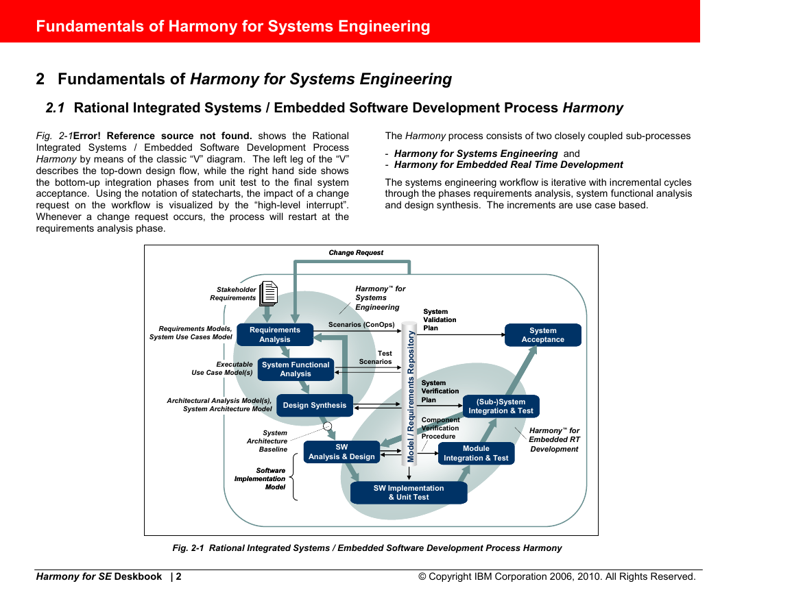
2.1 Rational Integrated Systems / Embedded Software Development Process Harmony
The Harmony process consists of two closely coupled sub-processes
- Harmony for Systems Engineering and
- Harmony for Embedded Real Time Development
The systems engineering workflow is iterative with incremental cycles
through the phases requirements analysis, system functional analysis
and design synthesis. The increments are use case based.
Change Request
Change Request
Harmony™ for
Systems
Engineering
Scenarios (ConOps)
System
System
Validation
Validation
Plan
Plan
y
r
o
t
i
System
System
Acceptance
Acceptance
Stakeholder
Requirements
Fig. 2-1Error! Reference source not found. shows the Rational
Integrated Systems / Embedded Software Development Process
Harmony by means of the classic “V” diagram. The left leg of the “V”
describes the top-down design flow, while the right hand side shows
the bottom-up integration phases from unit test to the final system
acceptance. Using the notation of statecharts, the impact of a change
request on the workflow is visualized by the “high-level interrupt”.
Whenever a change request occurs, the process will restart at the
requirements analysis phase.
Architectural Analysis Model(s),
System Architecture Model
Requirements Models,
System Use Cases Model
Software
Software
Implementation
Implementation
Model
Model
System
Architecture
Baseline
Requirements
Requirements
Analysis
Analysis
Executable
Use Case Model(s)
System Functional
System Functional
Analysis
Analysis
Design Synthesis
Design Synthesis
SW
SW
Analysis & Design
Analysis & Design
e
d
o
M
Module
Module
Integration & Test
Integration & Test
(Sub-)System
(Sub-)System
Integration & Test
Integration & Test
Harmony™ for
Embedded RT
Development
Test
Scenarios
s
o
p
e
R
s
t
n
e
m
e
r
i
u
q
e
R
/
l
System
System
Verification
Verification
Plan
Plan
Component
Verification
Procedure
SW Implementation
SW Implementation
& Unit Test
& Unit Test
Fig. 2-1 Rational Integrated Systems / Embedded Software Development Process Harmony
Harmony for SE Deskbook | 2
© Copyright IBM Corporation 2006, 2010. All Rights Reserved.
�


 2023年江西萍乡中考道德与法治真题及答案.doc
 2012年重庆南川中考生物真题及答案.doc
 2013年江西师范大学地理学综合及文艺理论基础考研真题.doc
 2020年四川甘孜小升初语文真题及答案I卷.doc
 2020年注册岩土工程师专业基础考试真题及答案.doc
 2023-2024学年福建省厦门市九年级上学期数学月考试题及答案.doc
 2021-2022学年辽宁省沈阳市大东区九年级上学期语文期末试题及答案.doc
 2022-2023学年北京东城区初三第一学期物理期末试卷及答案.doc
 2018上半年江西教师资格初中地理学科知识与教学能力真题及答案.doc
 2012年河北国家公务员申论考试真题及答案-省级.doc
 2020-2021学年江苏省扬州市江都区邵樊片九年级上学期数学第一次质量检测试题及答案.doc
 2022下半年黑龙江教师资格证中学综合素质真题及答案.doc