logo资料库

EFR32FG12系列用户手册.pdf

第1页 / 共265页
第2页 / 共265页
第3页 / 共265页
第4页 / 共265页
第5页 / 共265页
第6页 / 共265页
第7页 / 共265页
第8页 / 共265页
资料共265页,剩余部分请下载后查看
1. Feature List
2. Ordering Information
3. System Overview
3.1 Introduction
3.2 Radio
3.2.1 Antenna Interface
3.2.2 Fractional-N Frequency Synthesizer
3.2.3 Receiver Architecture
3.2.4 Transmitter Architecture
3.2.5 Wake on Radio
3.2.6 RFSENSE
3.2.7 Flexible Frame Handling
3.2.8 Packet and State Trace
3.2.9 Data Buffering
3.2.10 Radio Controller (RAC)
3.2.11 Random Number Generator
3.3 Power
3.3.1 Energy Management Unit (EMU)
3.3.2 DC-DC Converter
3.3.3 Power Domains
3.4 General Purpose Input/Output (GPIO)
3.5 Clocking
3.5.1 Clock Management Unit (CMU)
3.5.2 Internal and External Oscillators
3.6 Counters/Timers and PWM
3.6.1 Timer/Counter (TIMER)
3.6.2 Wide Timer/Counter (WTIMER)
3.6.3 Real Time Counter and Calendar (RTCC)
3.6.4 Low Energy Timer (LETIMER)
3.6.5 Ultra Low Power Wake-up Timer (CRYOTIMER)
3.6.6 Pulse Counter (PCNT)
3.6.7 Watchdog Timer (WDOG)
3.7 Communications and Other Digital Peripherals
3.7.1 Universal Synchronous/Asynchronous Receiver/Transmitter (USART)
3.7.2 Low Energy Universal Asynchronous Receiver/Transmitter (LEUART)
3.7.3 Inter-Integrated Circuit Interface (I2C)
3.7.4 Peripheral Reflex System (PRS)
3.7.5 Low Energy Sensor Interface (LESENSE)
3.8 Security Features
3.8.1 GPCRC (General Purpose Cyclic Redundancy Check)
3.8.2 Crypto Accelerator (CRYPTO)
3.8.3 True Random Number Generator (TRNG)
3.8.4 Security Management Unit (SMU)
3.9 Analog
3.9.1 Analog Port (APORT)
3.9.2 Analog Comparator (ACMP)
3.9.3 Analog to Digital Converter (ADC)
3.9.4 Capacitive Sense (CSEN)
3.9.5 Digital to Analog Current Converter (IDAC)
3.9.6 Digital to Analog Converter (VDAC)
3.9.7 Operational Amplifiers
3.10 Reset Management Unit (RMU)
3.11 Core and Memory
3.11.1 Processor Core
3.11.2 Memory System Controller (MSC)
3.11.3 Linked Direct Memory Access Controller (LDMA)
3.12 Memory Map
3.13 Configuration Summary
4. Electrical Specifications
4.1 Electrical Characteristics
4.1.1 Absolute Maximum Ratings
4.1.2 Operating Conditions
4.1.2.1 General Operating Conditions
4.1.3 DC-DC Converter
4.1.4 Current Consumption
4.1.4.1 Current Consumption 3.3 V without DC-DC Converter
4.1.4.2 Current Consumption 3.3 V using DC-DC Converter
4.1.4.3 Current Consumption 1.8 V without DC-DC Converter
4.1.4.4 Current Consumption Using Radio 3.3 V with DC-DC
4.1.5 Wake Up Times
4.1.6 Brown Out Detector (BOD)
4.1.7 Frequency Synthesizer
4.1.8 2.4 GHz RF Transceiver Characteristics
4.1.8.1 RF Transmitter General Characteristics for 2.4 GHz Band
4.1.8.2 RF Receiver General Characteristics for 2.4 GHz Band
4.1.8.3 RF Transmitter Characteristics for 1Mbps 2GFSK in the 2.4GHz Band, 1 Mbps Data Rate
4.1.8.4 RF Receiver Characteristics for 1Mbps 2GFSK in the 2.4GHz Band, 1 Mbps Data Rate
4.1.8.5 RF Transmitter Characteristics for 1Mbps 2GFSK in the 2.4GHz Band, 2 Mbps Data Rate
4.1.8.6 RF Receiver Characteristics for 1Mbps 2GFSK in the 2.4GHz Band, 2 Mbps Data Rate
4.1.8.7 RF Transmitter Characteristics for 802.15.4 DSSS-OQPSK in the 2.4 GHz Band
4.1.8.8 RF Receiver Characteristics for 802.15.4 DSSS-OQPSK in the 2.4 GHz Band
4.1.9 Sub-GHz RF Transceiver Characteristics
4.1.9.1 Sub-GHz RF Transmitter characteristics for 915 MHz Band
4.1.9.2 Sub-GHz RF Receiver Characteristics for 915 MHz Band
4.1.9.3 Sub-GHz RF Transmitter characteristics for 868 MHz Band
4.1.9.4 Sub-GHz RF Receiver Characteristics for 868 MHz Band
4.1.9.5 Sub-GHz RF Transmitter characteristics for 490 MHz Band
4.1.9.6 Sub-GHz RF Receiver Characteristics for 490 MHz Band
4.1.9.7 Sub-GHz RF Transmitter characteristics for 433 MHz Band
4.1.9.8 Sub-GHz RF Receiver Characteristics for 433 MHz Band
4.1.9.9 Sub-GHz RF Transmitter characteristics for 315 MHz Band
4.1.9.10 Sub-GHz RF Receiver Characteristics for 315 MHz Band
4.1.9.11 Sub-GHz RF Transmitter Characteristics for 169 MHz Band
4.1.9.12 Sub-GHz RF Receiver Characteristics for 169 MHz Band
4.1.10 Modem
4.1.11 Oscillators
4.1.11.1 Low-Frequency Crystal Oscillator (LFXO)
4.1.11.2 High-Frequency Crystal Oscillator (HFXO)
4.1.11.3 Low-Frequency RC Oscillator (LFRCO)
4.1.11.4 High-Freqency RC Oscillator (HFRCO)
4.1.11.5 Auxiliary High-Freqency RC Oscillator (AUXHFRCO)
4.1.11.6 Ultra-low Frequency RC Oscillator (ULFRCO)
4.1.12 Flash Memory Characteristics
4.1.13 General-Purpose I/O (GPIO)
4.1.14 Voltage Monitor (VMON)
4.1.15 Analog to Digital Converter (ADC)
4.1.16 Analog Comparator (ACMP)
4.1.17 Digital to Analog Converter (VDAC)
4.1.18 Current Digital to Analog Converter (IDAC)
4.1.19 Capacitive Sense (CSEN)
4.1.20 Operational Amplifier (OPAMP)
4.1.21 Pulse Counter (PCNT)
4.1.22 Analog Port (APORT)
4.1.23 I2C
4.1.23.1 I2C Standard-mode (Sm)
4.1.23.2 I2C Fast-mode (Fm)
4.1.23.3 I2C Fast-mode Plus (Fm+)
4.1.24 USART SPI
4.2 Typical Performance Curves
4.2.1 Supply Current
4.2.2 DC-DC Converter
4.2.3 2.4 GHz Radio
5. Typical Connection Diagrams
5.1 Power
5.2 RF Matching Networks
5.3 Other Connections
6. Pin Definitions
6.1 BGA125 2.4 GHz and Sub-GHz Device Pinout
6.1.1 BGA125 2.4 GHz and Sub-GHz GPIO Overview
6.2 BGA125 2.4 GHz Device Pinout
6.2.1 BGA125 2.4 GHz GPIO Overview
6.3 BGA125 Sub-GHz Device Pinout
6.3.1 BGA125 Sub-GHz GPIO Overview
6.4 QFN48 2.4 GHz and Sub-GHz Device Pinout
6.4.1 QFN48 2.4 GHz and Sub-GHz GPIO Overview
6.5 QFN48 2.4 GHz Device Pinout
6.5.1 QFN48 2.4 GHz GPIO Overview
6.6 QFN48 Sub-GHz Device Pinout
6.6.1 QFN48 Sub-GHz GPIO Overview
6.7 Alternate Functionality Overview
6.8 Analog Port (APORT) Client Maps
7. BGA125 Package Specifications
7.1 BGA125 Package Dimensions
7.2 BGA125 PCB Land Pattern
7.3 BGA125 Package Marking
8. QFN48 Package Specifications
8.1 QFN48 Package Dimensions
8.2 QFN48 PCB Land Pattern
8.3 QFN48 Package Marking
9. Revision History
9.1 Revision 0.6
9.2 Revision 0.5
9.3 Revision 0.2
Table of Contents
EFR32FG12 Flex Gecko Proprietary Protocol SoC Family Data Sheet The Flex Gecko proprietary protocol family of SoCs is part of the Wireless Gecko portfolio. Flex Gecko SoCs are ideal for enabling energy-friendly proprietary protocol networking for IoT devices. The single-die solution provides industry-leading energy efficiency, ultra-fast wakeup times, a scalable power amplifier, an integrated balun and no-compromise MCU fea- tures. Flex Gecko applications include: • Home and Building Automation and Security • Metering • Electronic Shelf Labels • Industrial Automation • Commercial and Retail Lighting and Sensing KEY FEATURES • 32-bit ARM® Cortex®-M4 core with 40 MHz maximum operating frequency • Up to 1 MB of flash and 256 kB of RAM • Pin-compatible with EFR32FG1 QFN48 devices (exceptions apply for 5V-tolerant pins) • 12-channel Peripheral Reflex System, Low-Energy Sensor Interface & Multi- channel Capacitive Sense Interface • Autonomous Hardware Crypto Accelerator and True Random Number Generator • Integrated PA with up to 19.5 dBm transmit power for 2.4 GHz and 20 dBm for Sub-GHz radios • Integrated balun for 2.4 GHz • Robust peripheral set and up to 65 GPIO Core / Memory Clock Management Energy Management ARM CortexTM M4 processor with DSP extensions and FPU Memory Protection Unit Flash Program Memory RAM Memory Debug Interface with ETM LDMA Controller High Frequency Crystal Oscillator Low Frequency RC Oscillator Low Frequency Crystal Oscillator High Frequency RC Oscillator Auxiliary High Frequency RC Oscillator Ultra Low Frequency RC Oscillator Voltage Monitor Power-On Reset Voltage Regulator DC-DC Converter Brown-Out Detector Other CRYPTO CRC True Random Number Generator SMU 32-bit bus Peripheral Reflex System Radio Transceiver I/O Ports Timers and Triggers Analog I/F RFSENSE Sub GHz LNA I RF Frontend PA Q RFSENSE 2.4 GHz BALUN LNA I RF Frontend PA DEMOD PGA IFADC To Sub GHz receive I/Q mixers and PA Frequency Synthesizer AGC MOD C R F C F U B C R C C A R To 2.4 GHz receive I/Q mixers and PA Lowest power mode with peripheral operational: Q To Sub GHz and 2.4 GHz PA Serial Interfaces USART Low Energy UARTTM External Interrupts General Purpose I/O Timer/Counter Protocol Timer Low Energy Timer Watchdog Timer I2C Pin Reset Pulse Counter Pin Wakeup Low Energy Sensor Interface Real Time Counter and Calendar Cryotimer ADC Analog Comparator IDAC Capacitive Sense VDAC Op-Amp EM0—Active EM1—Sleep EM2—Deep Sleep EM3—Stop EM4—Hibernate EM4—Shutoff silabs.com | Building a more connected world. This information applies to a product under development. Its characteristics and specifications are subject to change without notice. Preliminary Rev. 0.6
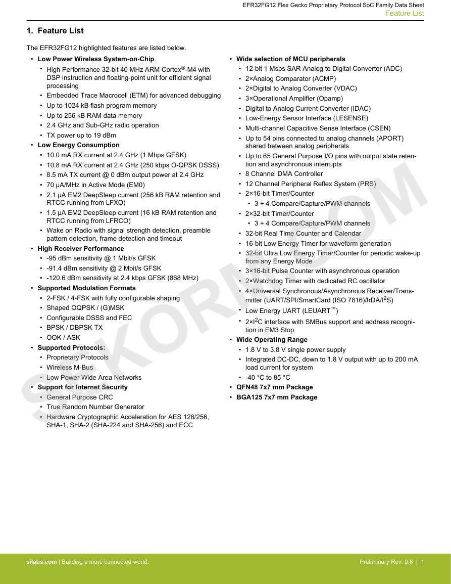
1. Feature List The EFR32FG12 highlighted features are listed below. • Low Power Wireless System-on-Chip. • High Performance 32-bit 40 MHz ARM Cortex®-M4 with DSP instruction and floating-point unit for efficient signal processing • Embedded Trace Macrocell (ETM) for advanced debugging • Up to 1024 kB flash program memory • Up to 256 kB RAM data memory • 2.4 GHz and Sub-GHz radio operation • TX power up to 19 dBm • Low Energy Consumption • 10.0 mA RX current at 2.4 GHz (1 Mbps GFSK) • 10.8 mA RX current at 2.4 GHz (250 kbps O-QPSK DSSS) • 8.5 mA TX current @ 0 dBm output power at 2.4 GHz • 70 μA/MHz in Active Mode (EM0) • 2.1 μA EM2 DeepSleep current (256 kB RAM retention and RTCC running from LFXO) • 1.5 μA EM2 DeepSleep current (16 kB RAM retention and RTCC running from LFRCO) • Wake on Radio with signal strength detection, preamble pattern detection, frame detection and timeout • High Receiver Performance • -95 dBm sensitivity @ 1 Mbit/s GFSK • -91.4 dBm sensitivity @ 2 Mbit/s GFSK • -120.6 dBm sensitivity at 2.4 kbps GFSK (868 MHz) • Supported Modulation Formats • 2-FSK / 4-FSK with fully configurable shaping • Shaped OQPSK / (G)MSK • Configurable DSSS and FEC • BPSK / DBPSK TX • OOK / ASK • Supported Protocols: • Proprietary Protocols • Wireless M-Bus • Low Power Wide Area Networks • Support for Internet Security • General Purpose CRC • True Random Number Generator • Hardware Cryptographic Acceleration for AES 128/256, SHA-1, SHA-2 (SHA-224 and SHA-256) and ECC EFR32FG12 Flex Gecko Proprietary Protocol SoC Family Data Sheet Feature List • Wide selection of MCU peripherals • 12-bit 1 Msps SAR Analog to Digital Converter (ADC) • 2×Analog Comparator (ACMP) • 2×Digital to Analog Converter (VDAC) • 3×Operational Amplifier (Opamp) • Digital to Analog Current Converter (IDAC) • Low-Energy Sensor Interface (LESENSE) • Multi-channel Capacitive Sense Interface (CSEN) • Up to 54 pins connected to analog channels (APORT) shared between analog peripherals • Up to 65 General Purpose I/O pins with output state reten- tion and asynchronous interrupts • 8 Channel DMA Controller • 12 Channel Peripheral Reflex System (PRS) • 2×16-bit Timer/Counter • 3 + 4 Compare/Capture/PWM channels • 2×32-bit Timer/Counter • 3 + 4 Compare/Capture/PWM channels • 32-bit Real Time Counter and Calendar • 16-bit Low Energy Timer for waveform generation • 32-bit Ultra Low Energy Timer/Counter for periodic wake-up from any Energy Mode • 3×16-bit Pulse Counter with asynchronous operation • 2×Watchdog Timer with dedicated RC oscillator • 4×Universal Synchronous/Asynchronous Receiver/Trans- mitter (UART/SPI/SmartCard (ISO 7816)/IrDA/I2S) • Low Energy UART (LEUART™) • 2×I2C interface with SMBus support and address recogni- tion in EM3 Stop • Wide Operating Range • 1.8 V to 3.8 V single power supply • Integrated DC-DC, down to 1.8 V output with up to 200 mA load current for system • -40 °C to 85 °C • QFN48 7x7 mm Package • BGA125 7x7 mm Package silabs.com | Building a more connected world. Preliminary Rev. 0.6 | 1
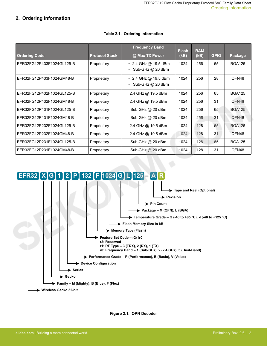
EFR32FG12 Flex Gecko Proprietary Protocol SoC Family Data Sheet Ordering Information 2. Ordering Information Table 2.1. Ordering Information Ordering Code Protocol Stack EFR32FG12P433F1024GL125-B Proprietary EFR32FG12P433F1024GM48-B Proprietary EFR32FG12P432F1024GL125-B EFR32FG12P432F1024GM48-B EFR32FG12P431F1024GL125-B EFR32FG12P431F1024GM48-B EFR32FG12P232F1024GL125-B EFR32FG12P232F1024GM48-B EFR32FG12P231F1024GL125-B EFR32FG12P231F1024GM48-B Proprietary Proprietary Proprietary Proprietary Proprietary Proprietary Proprietary Proprietary Frequency Band @ Max TX Power • 2.4 GHz @ 19.5 dBm • Sub-GHz @ 20 dBm • 2.4 GHz @ 19.5 dBm • Sub-GHz @ 20 dBm 2.4 GHz @ 19.5 dBm 2.4 GHz @ 19.5 dBm Sub-GHz @ 20 dBm Sub-GHz @ 20 dBm 2.4 GHz @ 19.5 dBm 2.4 GHz @ 19.5 dBm Sub-GHz @ 20 dBm Sub-GHz @ 20 dBm Flash (kB) 1024 RAM (kB) 256 1024 256 1024 1024 1024 1024 1024 1024 1024 1024 256 256 256 256 128 128 128 128 GPIO Package 65 28 65 31 65 31 65 31 65 31 BGA125 QFN48 BGA125 QFN48 BGA125 QFN48 BGA125 QFN48 BGA125 QFN48 EFR32 GX 1 2 P 132 F 1024 G L 125 – A R Tape and Reel (Optional) Revision Pin Count Package – M (QFN), L (BGA) Temperature Grade – G (-40 to +85 °C), -I (-40 to +125 °C) Flash Memory Size in kB Memory Type (Flash) Feature Set Code – r2r1r0 r2: Reserved r1: RF Type – 3 (TRX), 2 (RX), 1 (TX) r0: Frequency Band – 1 (Sub-GHz), 2 (2.4 GHz), 3 (Dual-Band) Performance Grade – P (Performance), B (Basic), V (Value) Device Configuration Series Gecko Family – M (Mighty), B (Blue), F (Flex) Wireless Gecko 32-bit Figure 2.1. OPN Decoder silabs.com | Building a more connected world. Preliminary Rev. 0.6 | 2
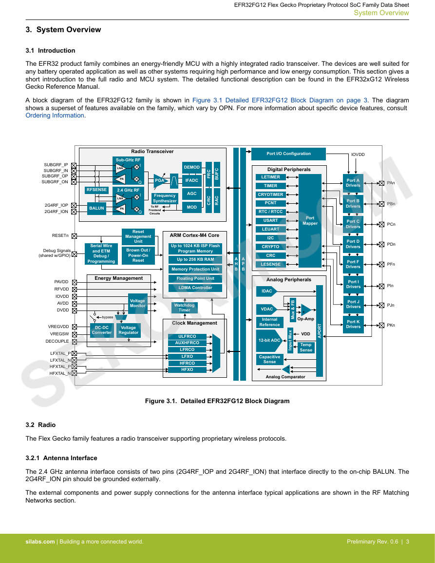
EFR32FG12 Flex Gecko Proprietary Protocol SoC Family Data Sheet System Overview 3. System Overview 3.1 Introduction The EFR32 product family combines an energy-friendly MCU with a highly integrated radio transceiver. The devices are well suited for any battery operated application as well as other systems requiring high performance and low energy consumption. This section gives a short introduction to the full radio and MCU system. The detailed functional description can be found in the EFR32xG12 Wireless Gecko Reference Manual. A block diagram of the EFR32FG12 family is shown in Figure 3.1 Detailed EFR32FG12 Block Diagram on page 3. The diagram shows a superset of features available on the family, which vary by OPN. For more information about specific device features, consult Ordering Information. Radio Transceiver Sub-GHz RF I LNA PA Q 2.4 GHz RF LNA PA I Q DEMOD PGA IFADC Frequency Synthesizer To RF Frontend Circuits AGC MOD C R F C F U B C R C C A R RFSENSE BALUN Serial Wire and ETM Debug / Programming Reset Management Unit Brown Out / Power-On Reset Energy Management Voltage Monitor bypass DC-DC Converter Voltage Regulator ARM Cortex-M4 Core Up to 1024 KB ISP Flash Program Memory Up to 256 KB RAM Memory Protection Unit Floating Point Unit LDMA Controller Watchdog Timer Clock Management ULFRCO AUXHFRCO LFRCO LFXO HFRCO HFXO SUBGRF_IP SUBGRF_IN SUBGRF_OP SUBGRF_ON 2G4RF_IOP 2G4RF_ION RESETn Debug Signals (shared w/GPIO) PAVDD RFVDD IOVDD AVDD DVDD VREGVDD VREGSW DECOUPLE LFXTAL_P LFXTAL_N HFXTAL_P HFXTAL_N Port I/O Configuration IOVDD Digital Peripherals Port A Drivers Port B Drivers Port C Drivers Port D Drivers Port F Drivers Port I Drivers Port J Drivers Port K Drivers PAn PBn PCn PDn PFn PIn PJn PKn LETIMER TIMER CRYOTIMER PCNT RTC / RTCC USART LEUART I2C CRYPTO CRC LESENSE A H B A P B Port Mapper Analog Peripherals IDAC VDAC Internal Reference 12-bit ADC Capacitive Sense B F & x u M - + Op-Amp T R O P A x u M t u p n I VDD Temp Sense + - Analog Comparator Figure 3.1. Detailed EFR32FG12 Block Diagram 3.2 Radio The Flex Gecko family features a radio transceiver supporting proprietary wireless protocols. 3.2.1 Antenna Interface The 2.4 GHz antenna interface consists of two pins (2G4RF_IOP and 2G4RF_ION) that interface directly to the on-chip BALUN. The 2G4RF_ION pin should be grounded externally. The external components and power supply connections for the antenna interface typical applications are shown in the RF Matching Networks section. silabs.com | Building a more connected world. Preliminary Rev. 0.6 | 3
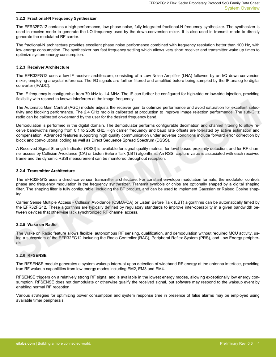
EFR32FG12 Flex Gecko Proprietary Protocol SoC Family Data Sheet System Overview 3.2.2 Fractional-N Frequency Synthesizer The EFR32FG12 contains a high performance, low phase noise, fully integrated fractional-N frequency synthesizer. The synthesizer is used in receive mode to generate the LO frequency used by the down-conversion mixer. It is also used in transmit mode to directly generate the modulated RF carrier. The fractional-N architecture provides excellent phase noise performance combined with frequency resolution better than 100 Hz, with low energy consumption. The synthesizer has fast frequency settling which allows very short receiver and transmitter wake up times to optimize system energy consumption. 3.2.3 Receiver Architecture The EFR32FG12 uses a low-IF receiver architecture, consisting of a Low-Noise Amplifier (LNA) followed by an I/Q down-conversion mixer, employing a crystal reference. The I/Q signals are further filtered and amplified before being sampled by the IF analog-to-digital converter (IFADC). The IF frequency is configurable from 70 kHz to 1.4 MHz. The IF can further be configured for high-side or low-side injection, providing flexibility with respect to known interferers at the image frequency. The Automatic Gain Control (AGC) module adjusts the receiver gain to optimize performance and avoid saturation for excellent selec- tivity and blocking performance. The 2.4 GHz radio is calibrated at production to improve image rejection performance. The sub-GHz radio can be calibrated on-demand by the user for the desired frequency band. Demodulation is performed in the digital domain. The demodulator performs configurable decimation and channel filtering to allow re- ceive bandwidths ranging from 0.1 to 2530 kHz. High carrier frequency and baud rate offsets are tolerated by active estimation and compensation. Advanced features supporting high quality communication under adverse conditions include forward error correction by block and convolutional coding as well as Direct Sequence Spread Spectrum (DSSS). A Received Signal Strength Indicator (RSSI) is available for signal quality metrics, for level-based proximity detection, and for RF chan- nel access by Collision Avoidance (CA) or Listen Before Talk (LBT) algorithms. An RSSI capture value is associated with each received frame and the dynamic RSSI measurement can be monitored throughout reception. 3.2.4 Transmitter Architecture The EFR32FG12 uses a direct-conversion transmitter architecture. For constant envelope modulation formats, the modulator controls phase and frequency modulation in the frequency synthesizer. Transmit symbols or chips are optionally shaped by a digital shaping filter. The shaping filter is fully configurable, including the BT product, and can be used to implement Gaussian or Raised Cosine shap- ing. Carrier Sense Multiple Access - Collision Avoidance (CSMA-CA) or Listen Before Talk (LBT) algorithms can be automatically timed by the EFR32FG12. These algorithms are typically defined by regulatory standards to improve inter-operability in a given bandwidth be- tween devices that otherwise lack synchronized RF channel access. 3.2.5 Wake on Radio The Wake on Radio feature allows flexible, autonomous RF sensing, qualification, and demodulation without required MCU activity, us- ing a subsystem of the EFR32FG12 including the Radio Controller (RAC), Peripheral Reflex System (PRS), and Low Energy peripher- als. 3.2.6 RFSENSE The RFSENSE module generates a system wakeup interrupt upon detection of wideband RF energy at the antenna interface, providing true RF wakeup capabilities from low energy modes including EM2, EM3 and EM4. RFSENSE triggers on a relatively strong RF signal and is available in the lowest energy modes, allowing exceptionally low energy con- sumption. RFSENSE does not demodulate or otherwise qualify the received signal, but software may respond to the wakeup event by enabling normal RF reception. Various strategies for optimizing power consumption and system response time in presence of false alarms may be employed using available timer peripherals. silabs.com | Building a more connected world. Preliminary Rev. 0.6 | 4
EFR32FG12 Flex Gecko Proprietary Protocol SoC Family Data Sheet System Overview 3.2.7 Flexible Frame Handling EFR32FG12 has an extensive and flexible frame handling support for easy implementation of even complex communication protocols. The Frame Controller (FRC) supports all low level and timing critical tasks together with the Radio Controller and Modulator/Demodula- tor: • Highly adjustable preamble length • Up to 2 simultaneous synchronization words, each up to 32 bits and providing separate interrupts • Frame disassembly and address matching (filtering) to accept or reject frames • Automatic ACK frame assembly and transmission • Fully flexible CRC generation and verification: • Multiple CRC values can be embedded in a single frame • 8, 16, 24 or 32-bit CRC value • Configurable CRC bit and byte ordering • Selectable bit-ordering (least significant or most significant bit first) • Optional data whitening • Optional Forward Error Correction (FEC), including convolutional encoding / decoding and block encoding / decoding • Half rate convolutional encoder and decoder with constraint lengths from 2 to 7 and optional puncturing • Optional symbol interleaving, typically used in combination with FEC • Symbol coding, such as Manchester or DSSS, or biphase space encoding using FEC hardware • UART encoding over air, with start and stop bit insertion / removal • Test mode support, such as modulated or unmodulated carrier output • Received frame timestamping 3.2.8 Packet and State Trace The EFR32FG12 Frame Controller has a packet and state trace unit that provides valuable information during the development phase. It features: • Non-intrusive trace of transmit data, receive data and state information • Data observability on a single-pin UART data output, or on a two-pin SPI data output • Configurable data output bitrate / baudrate • Multiplexed transmitted data, received data and state / meta information in a single serial data stream 3.2.9 Data Buffering The EFR32FG12 features an advanced Radio Buffer Controller (BUFC) capable of handling up to 4 buffers of adjustable size from 64 bytes to 4096 bytes. Each buffer can be used for RX, TX or both. The buffer data is located in RAM, enabling zero-copy operations. 3.2.10 Radio Controller (RAC) The Radio Controller controls the top level state of the radio subsystem in the EFR32FG12. It performs the following tasks: • Precisely-timed control of enabling and disabling of the receiver and transmitter circuitry • Run-time calibration of receiver, transmitter and frequency synthesizer • Detailed frame transmission timing, including optional LBT or CSMA-CA 3.2.11 Random Number Generator The Frame Controller (FRC) implements a random number generator that uses entropy gathered from noise in the RF receive chain. The data is suitable for use in cryptographic applications. Output from the random number generator can be used either directly or as a seed or entropy source for software-based random num- ber generator algorithms such as Fortuna. silabs.com | Building a more connected world. Preliminary Rev. 0.6 | 5
EFR32FG12 Flex Gecko Proprietary Protocol SoC Family Data Sheet System Overview 3.3 Power The EFR32FG12 has an Energy Management Unit (EMU) and efficient integrated regulators to generate internal supply voltages. Only a single external supply voltage is required, from which all internal voltages are created. An optional integrated DC-DC buck regulator can be utilized to further reduce the current consumption. The DC-DC regulator requires one external inductor and one external capaci- tor. The EFR32FG12 device family includes support for internal supply voltage scaling, as well as two different power domains groups for peripherals. These enhancements allow for further supply current reductions and lower overall power consumption. AVDD and VREGVDD need to be 1.8 V or higher for the MCU to operate across all conditions; however the rest of the system will operate down to 1.62 V, including the digital supply and I/O. This means that the device is fully compatible with 1.8 V components. Running from a sufficiently high supply, the device can use the DC-DC to regulate voltage not only for itself, but also for other PCB components, supplying up to a total of 200 mA. 3.3.1 Energy Management Unit (EMU) The Energy Management Unit manages transitions of energy modes in the device. Each energy mode defines which peripherals and features are available and the amount of current the device consumes. The EMU can also be used to turn off the power to unused RAM blocks, and it contains control registers for the DC-DC regulator and the Voltage Monitor (VMON). The VMON is used to monitor multi- ple supply voltages. It has multiple channels which can be programmed individually by the user to determine if a sensed supply has fallen below a chosen threshold. 3.3.2 DC-DC Converter The DC-DC buck converter covers a wide range of load currents and provides up to 90% efficiency in energy modes EM0, EM1, EM2 and EM3, and can supply up to 200 mA to the device and surrounding PCB components. Patented RF noise mitigation allows operation of the DC-DC converter without degrading sensitivity of radio components. Protection features include programmable current limiting, short-circuit protection, and dead-time protection. The DC-DC converter may also enter bypass mode when the input voltage is too low for efficient operation. In bypass mode, the DC-DC input supply is internally connected directly to its output through a low resistance switch. Bypass mode also supports in-rush current limiting to prevent input supply voltage droops due to excessive output current tran- sients. 3.3.3 Power Domains The EFR32FG12 has two peripheral power domains for operation in EM2 and lower. If all of the peripherals in a peripheral power do- main are configured as unused, the power domain for that group will be powered off in the low-power mode, reducing the overall cur- rent consumption of the device. Table 3.1. Peripheral Power Subdomains Peripheral Power Domain 1 Peripheral Power Domain 2 ACMP0 PCNT0 ADC0 LETIMER0 LESENSE APORT - - - ACMP1 PCNT1 PCNT2 CSEN DAC0 LEUART0 I2C0 I2C1 IDAC silabs.com | Building a more connected world. Preliminary Rev. 0.6 | 6
EFR32FG12 Flex Gecko Proprietary Protocol SoC Family Data Sheet System Overview 3.4 General Purpose Input/Output (GPIO) EFR32FG12 has up to 65 General Purpose Input/Output pins. Each GPIO pin can be individually configured as either an output or in- put. More advanced configurations including open-drain, open-source, and glitch-filtering can be configured for each individual GPIO pin. The GPIO pins can be overridden by peripheral connections, like SPI communication. Each peripheral connection can be routed to several GPIO pins on the device. The input value of a GPIO pin can be routed through the Peripheral Reflex System to other peripher- als. The GPIO subsystem supports asynchronous external pin interrupts. 3.5 Clocking 3.5.1 Clock Management Unit (CMU) The Clock Management Unit controls oscillators and clocks in the EFR32FG12. Individual enabling and disabling of clocks to all periph- eral modules is performed by the CMU. The CMU also controls enabling and configuration of the oscillators. A high degree of flexibility allows software to optimize energy consumption in any specific application by minimizing power dissipation in unused peripherals and oscillators. 3.5.2 Internal and External Oscillators The EFR32FG12 supports two crystal oscillators and fully integrates four RC oscillators, listed below. • A high frequency crystal oscillator (HFXO) with integrated load capacitors, tunable in small steps, provides a precise timing refer- ence for the MCU. Crystal frequencies in the range from 38 to 40 MHz are supported. An external clock source such as a TCXO can also be applied to the HFXO input for improved accuracy over temperature. • A 32.768 kHz crystal oscillator (LFXO) provides an accurate timing reference for low energy modes. • An integrated high frequency RC oscillator (HFRCO) is available for the MCU system, when crystal accuracy is not required. The HFRCO employs fast startup at minimal energy consumption combined with a wide frequency range. • An integrated auxilliary high frequency RC oscillator (AUXHFRCO) is available for timing the general-purpose ADC and the Serial Wire debug port with a wide frequency range. • An integrated low frequency 32.768 kHz RC oscillator (LFRCO) can be used as a timing reference in low energy modes, when crys- tal accuracy is not required. • An integrated ultra-low frequency 1 kHz RC oscillator (ULFRCO) is available to provide a timing reference at the lowest energy con- sumption in low energy modes. 3.6 Counters/Timers and PWM 3.6.1 Timer/Counter (TIMER) TIMER peripherals keep track of timing, count events, generate PWM outputs and trigger timed actions in other peripherals through the PRS system. The core of each TIMER is a 16-bit counter with up to 4 compare/capture channels. Each channel is configurable in one of three modes. In capture mode, the counter state is stored in a buffer at a selected input event. In compare mode, the channel output reflects the comparison of the counter to a programmed threshold value. In PWM mode, the TIMER supports generation of pulse-width modulation (PWM) outputs of arbitrary waveforms defined by the sequence of values written to the compare registers, with optional dead-time insertion available in timer unit TIMER_0 only. 3.6.2 Wide Timer/Counter (WTIMER) WTIMER peripherals function just as TIMER peripherals, but are 32 bits wide. They keep track of timing, count events, generate PWM outputs and trigger timed actions in other peripherals through the PRS system. The core of each WTIMER is a 32-bit counter with up to 4 compare/capture channels. Each channel is configurable in one of three modes. In capture mode, the counter state is stored in a buffer at a selected input event. In compare mode, the channel output reflects the comparison of the counter to a programmed thresh- old value. In PWM mode, the WTIMER supports generation of pulse-width modulation (PWM) outputs of arbitrary waveforms defined by the sequence of values written to the compare registers, with optional dead-time insertion available in timer unit WTIMER_0 only. 3.6.3 Real Time Counter and Calendar (RTCC) The Real Time Counter and Calendar (RTCC) is a 32-bit counter providing timekeeping in all energy modes. The RTCC includes a Binary Coded Decimal (BCD) calendar mode for easy time and date keeping. The RTCC can be clocked by any of the on-board oscilla- tors with the exception of the AUXHFRCO, and it is capable of providing system wake-up at user defined instances. When receiving frames, the RTCC value can be used for timestamping. The RTCC includes 128 bytes of general purpose data retention, allowing easy and convenient data storage in all energy modes. silabs.com | Building a more connected world. Preliminary Rev. 0.6 | 7
分享到:
收藏