MSM8960 OV9740 摄像头调试
【摘要】
本文讲述 OV9740 在 MSM8960 上的调试过程,以及调试的过程中遇到的问题。
一、问题的提出
OV9740 摄像头是一个 YUV 输出的 1M sensor,调试起来应该比较简单,上电
之后 I2C 调试顺利通过,一般情况下,对于 YUVsensor,I2C 通过之后,写入寄存
器参数之后基本上可以预览,但是在调试 OV9740 的过程中,I2C 通了之后,写入
寄存器参数之后,图像没有出来,这是什么原因呢?
二、解决思路
摄像头 I2C 正常,说明上电功能已经正常,应该在寄存器配置、settle count、vt
pixel clk、op pixel clk 这几个方面存在问题。
三、实现情况
1、寄存器配置:
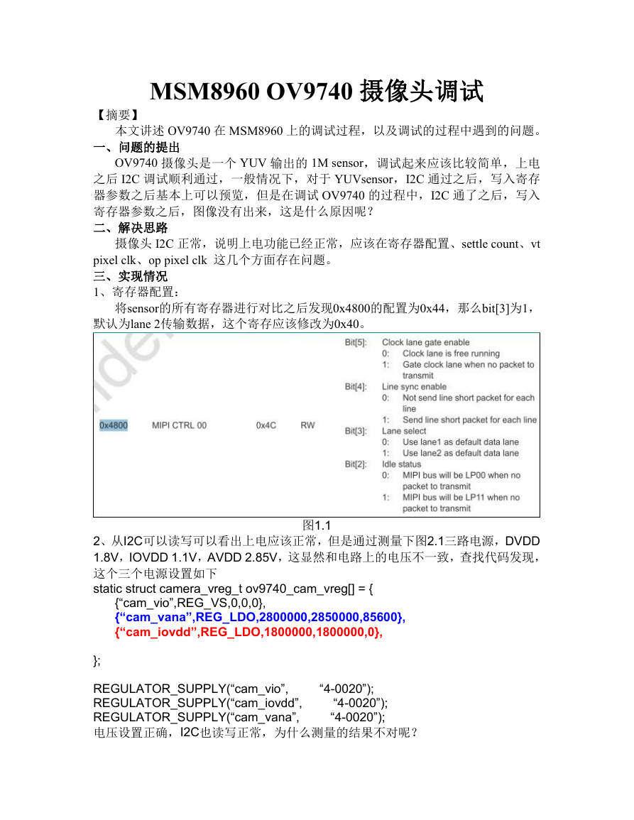
将sensor的所有寄存器进行对比之后发现0x4800的配置为0x44,那么bit[3]为1,
默认为lane 2传输数据,这个寄存应该修改为0x40。
图1.1
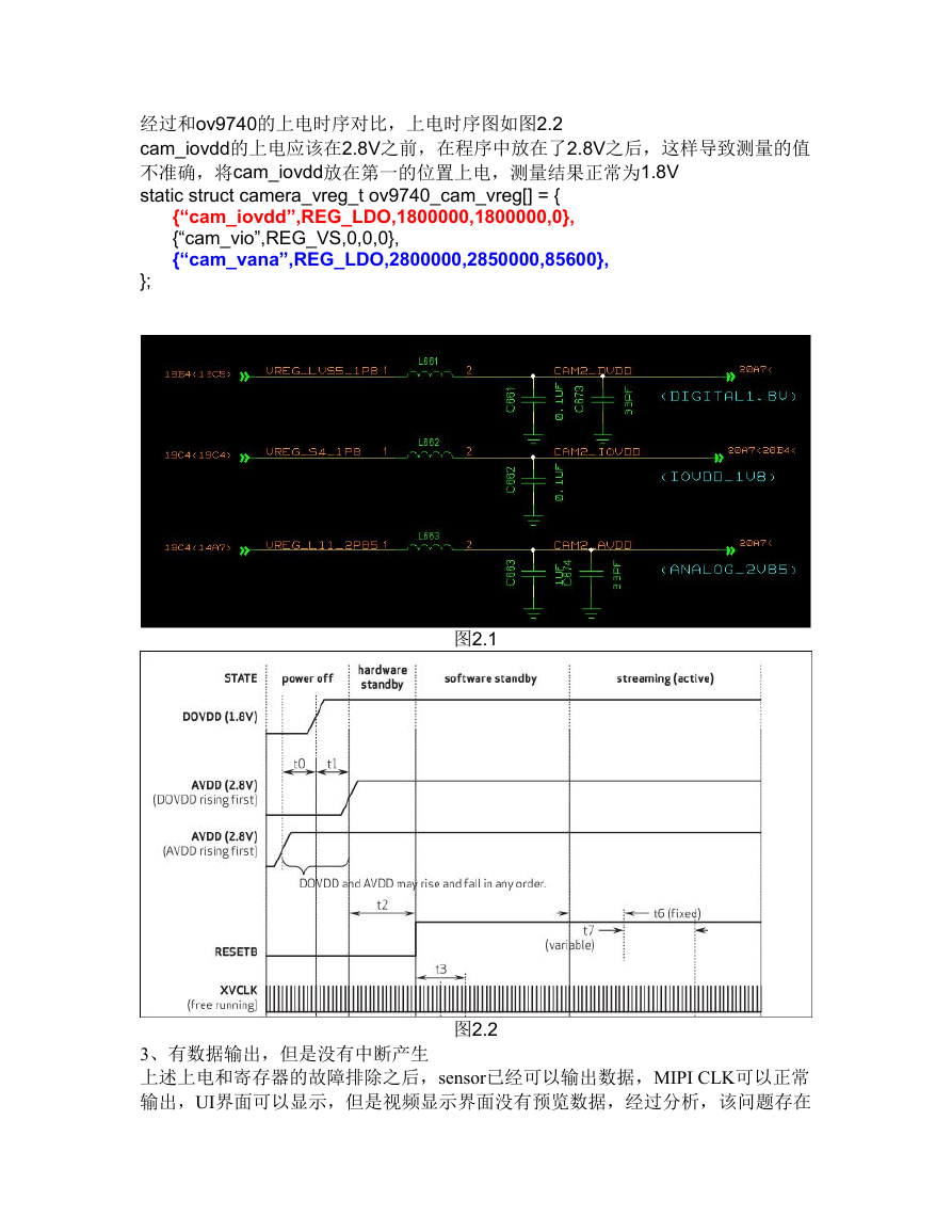
2、从I2C可以读写可以看出上电应该正常,但是通过测量下图2.1三路电源,DVDD
1.8V,IOVDD 1.1V,AVDD 2.85V,这显然和电路上的电压不一致,查找代码发现,
这个三个电源设置如下
static struct camera_vreg_t ov9740_cam_vreg[] = {
{“cam_vio”,REG_VS,0,0,0},
{“cam_vana”,REG_LDO,2800000,2850000,85600},
{“cam_iovdd”,REG_LDO,1800000,1800000,0},
};
REGULATOR_SUPPLY(“cam_vio”,
REGULATOR_SUPPLY(“cam_iovdd”,
REGULATOR_SUPPLY(“cam_vana”,
电压设置正确,I2C也读写正常,为什么测量的结果不对呢?
“4-0020”);
“4-0020”);
“4-0020”);
�
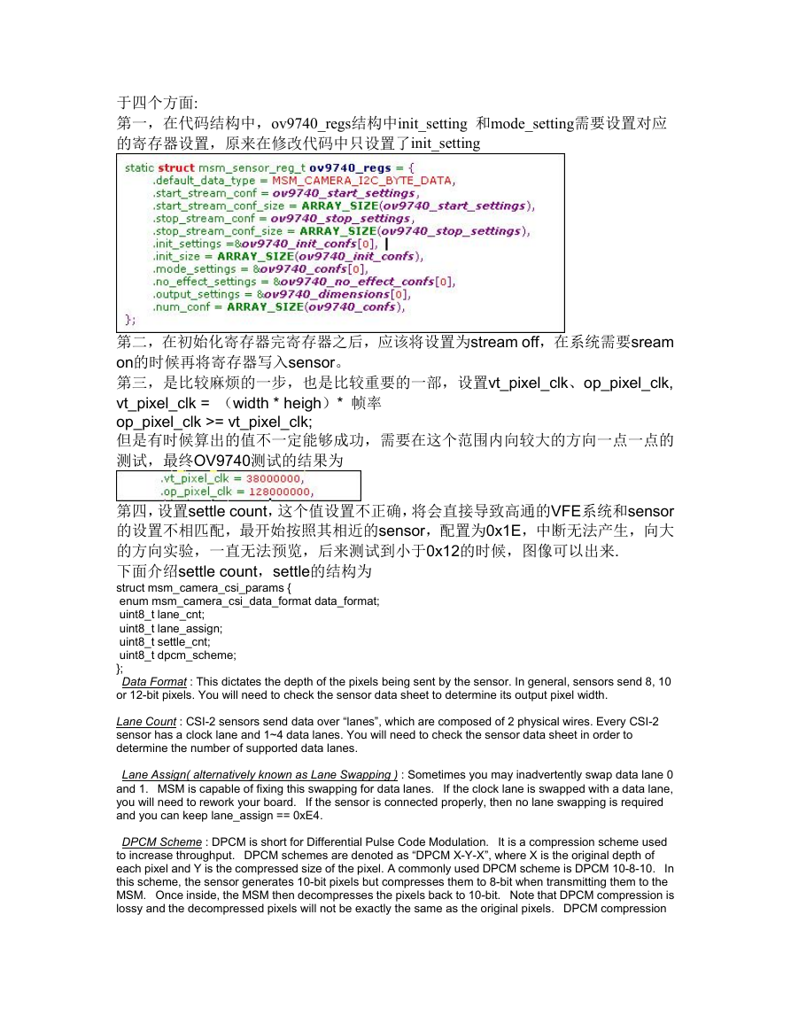
经过和ov9740的上电时序对比,上电时序图如图2.2
cam_iovdd的上电应该在2.8V之前,在程序中放在了2.8V之后,这样导致测量的值
不准确,将cam_iovdd放在第一的位置上电,测量结果正常为1.8V
static struct camera_vreg_t ov9740_cam_vreg[] = {
{“cam_iovdd”,REG_LDO,1800000,1800000,0},
{“cam_vio”,REG_VS,0,0,0},
{“cam_vana”,REG_LDO,2800000,2850000,85600},
};
图2.1
3、有数据输出,但是没有中断产生
上述上电和寄存器的故障排除之后,sensor已经可以输出数据,MIPI CLK可以正常
输出,UI界面可以显示,但是视频显示界面没有预览数据,经过分析,该问题存在
图2.2
�
于四个方面:
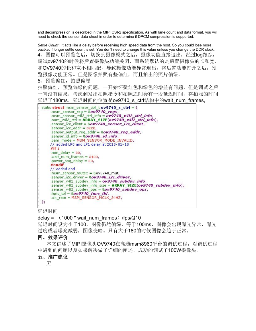
第一,在代码结构中,ov9740_regs结构中init_setting 和mode_setting需要设置对应
的寄存器设置,原来在修改代码中只设置了init_setting
第二,在初始化寄存器完寄存器之后,应该将设置为stream off,在系统需要sream
on的时候再将寄存器写入sensor。
第三,是比较麻烦的一步,也是比较重要的一部,设置vt_pixel_clk、op_pixel_clk,
vt_pixel_clk = (width * heigh)* 帧率
op_pixel_clk >= vt_pixel_clk;
但是有时候算出的值不一定能够成功,需要在这个范围内向较大的方向一点一点的
测试,最终OV9740测试的结果为
第四,设置settle count,这个值设置不正确,将会直接导致高通的VFE系统和sensor
的设置不相匹配,最开始按照其相近的sensor,配置为0x1E,中断无法产生,向大
的方向实验,一直无法预览,后来测试到小于0x12的时候,图像可以出来.
下面介绍settle count,settle的结构为
struct msm_camera_csi_params {
enum msm_camera_csi_data_format data_format;
uint8_t lane_cnt;
uint8_t lane_assign;
uint8_t settle_cnt;
uint8_t dpcm_scheme;
};
Data Format : This dictates the depth of the pixels being sent by the sensor. In general, sensors send 8, 10
or 12-bit pixels. You will need to check the sensor data sheet to determine its output pixel width.
Lane Count : CSI-2 sensors send data over “lanes”, which are composed of 2 physical wires. Every CSI-2
sensor has a clock lane and 1~4 data lanes. You will need to check the sensor data sheet in order to
determine the number of supported data lanes.
Lane Assign( alternatively known as Lane Swapping ) : Sometimes you may inadvertently swap data lane 0
and 1. MSM is capable of fixing this swapping for data lanes.
If the clock lane is swapped with a data lane,
you will need to rework your board.
and you can keep lane_assign == 0xE4.
If the sensor is connected properly, then no lane swapping is required
DPCM Scheme : DPCM is short for Differential Pulse Code Modulation.
to increase throughput. DPCM schemes are denoted as “DPCM X-Y-X”, where X is the original depth of
each pixel and Y is the compressed size of the pixel. A commonly used DPCM scheme is DPCM 10-8-10.
In
this scheme, the sensor generates 10-bit pixels but compresses them to 8-bit when transmitting them to the
MSM. Once inside, the MSM then decompresses the pixels back to 10-bit. Note that DPCM compression is
lossy and the decompressed pixels will not be exactly the same as the original pixels. DPCM compression
It is a compression scheme used
�
and decompression is described in the MIPI CSI-2 specification. As with lane count and data format, you will
need to check the sensor data sheet in order to determine if DPCM compression is supported.
Settle Count : It acts like a delay before receiving high speed data from the host. So you could lose more
pactket if longer settle count is set. You don't need to change this value unless you change the DDR clock.
4、图像可以预览之后,切换到摄像模式之后,摄像功能直接退出,经过log跟踪,
调试ov9740的时候将后置摄像头功能关闭,而系统默认的是后置摄像头的长和宽,
和OV9740的长和宽不相匹配,导致摄像功能异常退出,将后置功能打开之后,预
览摄像功能正常。但是图像拍照有些偏红,而且拍出的照片偏绿。
5、预览偏红,拍照偏绿
拍照偏红,预览偏绿的问题,一开始怀疑红色和绿色的增益有问题,但是调试之后
一直没有结果,考虑到发出拍照指令和拍照之间会有一段延迟时间,将拍照的时间
延迟了180ms,延迟时间的位置是ov9740_s_ctrl结构中的wait_num_frames,
延迟时间
delay = (1000 * wait_num_frames)/fps/Q10
延迟时间设为小于100,图像仍然偏绿,等于100ms,图像会出现曝光异常,曝光
过度或者曝光减弱,图像变暗。只有大于180的时候图像会趋于正常。
四、效果评价
本文讲述了MIPI摄像头OV9740在高通msm8960平台的调试过程,对调试过程
中遇到的问题以及如果解决做了详细的阐述,成功的调试了100W摄像头。
五、推广建议
无
�
内部公开▲
本文所有信息为中兴通讯股份有限公司内部信息,未经允许,不得外传 第 5页,共 5页
�


 2023年江西萍乡中考道德与法治真题及答案.doc
 2012年重庆南川中考生物真题及答案.doc
 2013年江西师范大学地理学综合及文艺理论基础考研真题.doc
 2020年四川甘孜小升初语文真题及答案I卷.doc
 2020年注册岩土工程师专业基础考试真题及答案.doc
 2023-2024学年福建省厦门市九年级上学期数学月考试题及答案.doc
 2021-2022学年辽宁省沈阳市大东区九年级上学期语文期末试题及答案.doc
 2022-2023学年北京东城区初三第一学期物理期末试卷及答案.doc
 2018上半年江西教师资格初中地理学科知识与教学能力真题及答案.doc
 2012年河北国家公务员申论考试真题及答案-省级.doc
 2020-2021学年江苏省扬州市江都区邵樊片九年级上学期数学第一次质量检测试题及答案.doc
 2022下半年黑龙江教师资格证中学综合素质真题及答案.doc