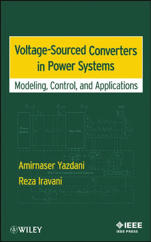
VOLTAGE-SOURCED CONVERTERS IN POWER SYSTEMS
CONTENTS
PREFACE
ACKNOWLEDGMENTS
ACRONYMS
1 Electronic Power Conversion
1.1 Introduction
1.2 Power-Electronic Converters and Converter Systems
1.3 Applications of Electronic Converters in Power Systems
1.4 Power-Electronic Switches
1.4.1 Switch Classification
1.4.2 Switch Characteristics
1.5 Classification of Converters
1.5.1 Classification Based on Commutation Process
1.5.2 Classification Based on Terminal Voltage and Current Waveforms
1.6 Voltage-Sourced Converter (VSC)
1.7 Basic Configurations
1.7.1 Multimodule VSC Systems
1.7.2 Multilevel VSC Systems
1.8 Scope of the Book
PART I FUNDAMENTALS
2 DC/AC Half-Bridge Converter
2.1 Introduction
2.2 Converter Structure
2.3 Principles of Operation
2.3.1 Pulse-Width Modulation (PWM)
2.3.2 Converter Waveforms
2.4 Converter Switched Model
2.5 Converter Averaged Model
2.6 Nonideal Half-Bridge Converter
2.6.1 Analysis of Nonideal Half-Bridge Converter: Positive AC-Side Current
2.6.2 Analysis of Nonideal Converter: Negative AC-Side Current
2.6.3 Averaged Model of Nonideal Half-Bridge Converter
3 Control of Half-Bridge Converter
3.1 Introduction
3.2 AC-Side Control Model of Half-Bridge Converter
3.3 Control of Half-Bridge Converter
3.4 Feed-Forward Compensation
3.4.1 Impact on Start-Up Transient
3.4.2 Impact on Dynamic Coupling Between Converter System and AC System
3.4.3 Impact on Disturbance Rejection Capability
3.5 Sinusoidal Command Following
4 Space Phasors and Two-Dimensional Frames
4.1 Introduction
4.2 Space-Phasor Representation of a Balanced Three-Phase Function
4.2.1 Definition of Space Phasor
4.2.2 Changing the Amplitude and Phase Angle of a Three-phase Signal
4.2.3 Generating a Controllable-Amplitude/Controllable-Frequency Three-Phase Signal
4.2.4 Space-Phasor Representation of Harmonics
4.3 Space-Phasor Representation of Three-Phase Systems
4.3.1 Decoupled Symmetrical Three-Phase Systems
4.3.2 Coupled Symmetrical Three-Phase Systems
4.3.3 Asymmetrical Three-Phase Systems
4.4 Power in Three-Wire Three-Phase Systems
4.5 αβ-Frame Representation and Control of Three-Phase Signals and Systems
4.5.1 αβ-Frame Representation of a Space Phasor
4.5.2 Realization of Signal Generators/Conditioners in αβ-Frame
4.5.3 Formulation of Power in αβ-Frame
4.5.4 Control in αβ-Frame
4.5.5 Representation of Systems in αβ-Frame
4.6 dq-Frame Representation and Control of Three-Phase Systems
4.6.1 dq-Frame Representation of a Space Phasor
4.6.2 Formulation of Power in dq-Frame
4.6.3 Control in dq-Frame
4.6.4 Representation of Systems in dq-Frame
5 Two-Level, Three-Phase Voltage-Sourced Converter
5.1 Introduction
5.2 Two-Level Voltage-Sourced Converter
5.2.1 Circuit Structure
5.2.2 Principles of Operation
5.2.3 Power Loss of Nonideal Two-Level VSC
5.3 Models and Control of Two-Level VSC
5.3.1 Averaged Model of Two-Level VSC
5.3.2 Model of Two-Level VSC in αβ-Frame
5.3.3 Model and Control of Two-Level VSC in dq-Frame
5.4 Classification of VSC Systems
6 Three-Level, Three-Phase, Neutral-Point Clamped, Voltage-Sourced Converter
6.1 Introduction
6.2 Three-Level Half-Bridge NPC
6.2.1 Generating Positive AC-Side Voltages
6.2.2 Generating Negative AC-Side Voltages
6.3 PWM Scheme For Three-Level Half-Bridge NPC
6.4 Switched Model of Three-Level Half-Bridge NPC
6.4.1 Switched AC-Side Terminal Voltage
6.4.2 Switched DC-Side Terminal Currents
6.5 Averaged Model of Three-Level Half-Bridge NPC
6.5.1 Averaged AC-Side Terminal Voltage
6.5.2 Averaged DC-Side Terminal Currents
6.6 Three-Level NPC
6.6.1 Circuit Structure
6.6.2 Principles of Operation
6.6.3 Midpoint Current
6.6.4 Three-Level NPC with Impressed DC-Side Voltages
6.7 Three-Level NPC with Capacitive DC-Side Voltage Divider
6.7.1 Partial DC-Side Voltage Drift Phenomenon
6.7.2 DC-Side Voltage Equalization
6.7.3 Derivation of DC-Side Currents
6.7.4 Unified Models of Three-Level NPC and Two-Level VSC
6.7.5 Impact of DC Capacitors Voltage Ripple on AC-Side Harmonics
7 Grid-Imposed Frequency VSC System: Control in αβ-Frame
7.1 Introduction
7.2 Structure of Grid-Imposed Frequency VSC System
7.3 Real-/Reactive-Power Controller
7.3.1 Current-Mode Versus Voltage-Mode Control
7.3.2 Dynamic Model of Real-/Reactive-Power Controller
7.3.3 Current-Mode Control of Real-/Reactive-Power Controller
7.3.4 Selection of DC-Bus Voltage Level
7.3.5 Trade-Offs and Practical Considerations
7.3.6 PWM with Third-Harmonic Injection
7.4 Real-/Reactive-Power Controller Based on Three-Level NPC
7.4.1 Midpoint Current of Three-level NPC Based on Third-Harmonic Injected PWM
7.5 Controlled DC-Voltage Power Port
7.5.1 Model of Controlled DC-Voltage Power Port
7.5.2 DC-Bus Voltage Control in Controlled DC-Voltage Power Port
7.5.3 Simplified and Accurate Models
8 Grid-Imposed Frequency VSC System: Control in dq-Frame
8.1 Introduction
8.2 Structure of Grid-Imposed Frequency VSC System
8.3 Real-/Reactive-Power Controller
8.3.1 Current-Mode Versus Voltage-Mode Control
8.3.2 Representation of Space Phasors in dq-Frame
8.3.3 Dynamic Model of Real-/Reactive-Power Controller
8.3.4 Phase-Locked Loop (PLL)
8.3.5 Compensator Design for PLL
8.4 Current-Mode Control of Real-/Reactive-Power Controller
8.4.1 VSC Current Control
8.4.2 Selection of DC-Bus Voltage Level
8.4.3 AC-Side Equivalent Circuit
8.4.4 PWM with Third-Harmonic Injection
8.5 Real-/Reactive-Power Controller Based on Three-Level NPC
8.6 Controlled DC-Voltage Power Port
8.6.1 Model of Controlled DC-Voltage Power Port
8.6.2 Control of Controlled DC-Voltage Power Port
8.6.3 Simplified and Accurate Models
9 Controlled-Frequency VSC System
9.1 Introduction
9.2 Structure of Controlled-Frequency VSC System
9.3 Model of Controlled-Frequency VSC System
9.4 Voltage Control
9.4.1 Autonomous Operation
10 Variable-Frequency VSC System
10.1 Introduction
10.2 Structure of Variable-Frequency VSC System
10.3 Control of Variable-Frequency VSC System
10.3.1 Asynchronous Machine
10.3.2 Doubly-Fed Asynchronous Machine
10.3.3 Permanent-Magnet Synchronous Machine
PART II APPLICATIONS
11 Static Compensator (STATCOM)
11.1 Introduction
11.2 Controlled DC-Voltage Power Port
11.3 STATCOM Structure
11.4 Dynamic Model for PCC Voltage Control
11.4.1 Large-Signal Model of PCC Voltage Dynamics
11.4.2 Small-Signal Model of PCC Voltage Dynamics
11.4.3 Steady-State Operating Point
11.5 Approximate Model of PCC Voltage Dynamics
11.6 STATCOM Control
11.7 Compensator Design for PCC Voltage Controller
11.8 Model Evaluation
12 Back-to-Back HVDC Conversion System
12.1 Introduction
12.2 HVDC System Structure
12.3 HVDC System Model
12.3.1 Grid and Interface Transformer Models
12.3.2 Back-to-Back Converter System Model
12.4 HVDC System Control
12.4.1 Phase-Locked Loop (PLL)
12.4.2 dq-Frame Current-Control Scheme
12.4.3 PWM Gating Signal Generator
12.4.4 Partial DC-Side Voltage Equalization
12.4.5 Power Flow Control
12.4.6 DC-Bus Voltage Regulation
12.5 HVDC System Performance Under an Asymmetrical Fault
12.5.1 PCC Voltage Under an Asymmetrical Fault
12.5.2 Performance of PLL Under an Asymmetrical Fault
12.5.3 Performance of dq-Frame Current-Control Scheme Under an Asymmetrical Fault
12.5.4 Dynamics of DC-Bus Voltage Under an Asymmetrical Fault
12.5.5 Generation of Low-Order Harmonics Under an Asymmetrical Fault
12.5.6 Steady-State Power-Flow Under an Asymmetrical Fault
12.5.7 DC-Bus Voltage Control Under an Asymmetrical Fault
13 Variable-Speed Wind-Power System
13.1 Introduction
13.2 Constant-Speed and Variable-Speed Wind-Power Systems
13.2.1 Constant-Speed Wind-Power Systems
13.2.2 Variable-Speed Wind-Power Systems
13.3 Wind Turbine Characteristics
13.4 Maximum Power Extraction from A Variable-Speed Wind-Power System
13.5 Variable-Speed Wind-Power System Based on Doubly-Fed Asynchronous Machine
13.5.1 Structure of the Doubly-Fed Asynchronous Machine-Based Wind-Power System
13.5.2 Machine Torque Control by Variable-Frequency VSC System
13.5.3 DC-Bus Voltage Regulation by Controlled DC-Voltage Power Port
13.5.4 Compensator Design for Controlled DC-Voltage Power Port
APPENDIX A: Space-Phasor Representation of Symmetrical Three-Phase Electric Machines
A.1 Introduction
A.2 Structure of Symmetrical Three-Phase Machine
A.3 Machine Electrical Model
A.3.1 Terminal Voltage/Current Equations
A.3.2 Stator Flux Space Phasor
A.3.3 Rotor Flux Space Phasor
A.3.4 Machine Electrical Torque
A.4 Machine Equivalent Circuit
A.4.1 Machine Dynamic Equivalent Circuit
A.4.2 Machine Steady-State Equivalent Circuit
A.5 Permanent-Magnet Synchronous Machine (PMSM)
A.5.1 PMSM Electrical Model
A.5.2 PMSM Steady-State Equivalent Circuit
APPENDIX B: Per-Unit Values for VSC Systems
B.1 Introduction
B.1.1 Base Values for AC-Side Quantities
B.1.2 Base Values for DC-Side Quantities
REFERENCES
INDEX




 2023年江西萍乡中考道德与法治真题及答案.doc
 2012年重庆南川中考生物真题及答案.doc
 2013年江西师范大学地理学综合及文艺理论基础考研真题.doc
 2020年四川甘孜小升初语文真题及答案I卷.doc
 2020年注册岩土工程师专业基础考试真题及答案.doc
 2023-2024学年福建省厦门市九年级上学期数学月考试题及答案.doc
 2021-2022学年辽宁省沈阳市大东区九年级上学期语文期末试题及答案.doc
 2022-2023学年北京东城区初三第一学期物理期末试卷及答案.doc
 2018上半年江西教师资格初中地理学科知识与教学能力真题及答案.doc
 2012年河北国家公务员申论考试真题及答案-省级.doc
 2020-2021学年江苏省扬州市江都区邵樊片九年级上学期数学第一次质量检测试题及答案.doc
 2022下半年黑龙江教师资格证中学综合素质真题及答案.doc