说明:这篇课题设计是小酒花生为同学特别制作(本人交的不是这篇)! 如果需要可以稍微
修个别地方,若觉得不好很满意,自己可以设计更好的;若有不妥之处,还请多多指正,
谢谢!!!
多路防盗报警系统设计与仿真
(物信学院 08 电科二班 XXX 20081030XX)
摘要:生活中有许多贵重物品基本上都是被破门而入,然后剪断或拔掉其连接线而失盗的,
本课题设计的报警器就是基于这个原理,只要安装线被剪断或者拔掉就会长时间发出报警
声,从而达到报警的目的。本课题设计是基于 LM358 芯片,结合电路仿真软件(如 orCAD)
模拟和仿真防盗报警器的工作原理和过程。
关键词:LM358
orCAD
IC
课题背景:
防盗报警是是预防抢劫、盗窃等意外事件的重要设施,一旦发生突发事件,就能通过声
光警报或电子地图提示值班人员出事地点,使于迅速采取应急措施。防盗报警主机与出入口
控制系统、闭路电视监控系统、访客对讲系统和电子巡更系统等一起构成了安全防范系统。
防盗报警系统的设备一般分为:前端探测器,报警控制器。报警控制器是一台主机(如
电脑的主机一样)是用来处理,包括有线/无线信号的处理,系统本身故障的检测,电源部
分,信号输入,信号输出,内置拨号器等这个方面组成,一个防盗报警系统报警控制器是必
不可少的。前端探测器包括有:门磁开关、玻璃破碎探测器、红外探测器和红外/微波双鉴
器、紧急呼救按钮。
防盗报警器是用物理方法或电子技术,自动探测发生在布防监测区域内的侵入行为,产
生报警信号,并辅助提示值班人员发生报警的区域部位,显示可能采取的对策的系统。防盗
报警系统是预防抢劫、盗窃等意外事件的重要设施。一旦发生突发事件,就能通过声光报警
信号在安保控制中心准确显示出事地点,使于迅速采取应急措施。防盗报警系统与出入口控
制系统、闭路电视监控系统、访客对讲系统和电子巡更系统等一起构成了入侵防范系统。防
盗报警系统通常由探测器(又称防盗报警器)、传输通道和报警控制器三部分构成。 报警探
测器是由传感器和信号处理组成的用来探测入侵者入侵行为的电子和机械部件组成的装置,
是防盗报警系统的核心,而传感器又是报警探测器的核心元件。采用不同原理的传感器件,
可以构成不同种类、不同用途、达到不同探测目的的报警探测装置。
本次设计的报警器具有语音报警和断线报警功能,还有小型充电电池,让电路工作可靠、
安全性能高、容易实现等特点,此外在设计的过程中也进一步的了解了比较器的原理及应用。
第 1页(共 12页)
�
基本原理:
LM358 内部包括有两个独立的、高增益、内部频率
补偿的双运算放大器,适合于电源电压范围很宽的单电
源使用,也适用于双电源工作模式,在推荐的工作条件
下,电源电流与电源电压无关。它的使用范围包括传感
放大器、直流增益模块和其他所有可用单电源供电的使
用运算放大器的场合。
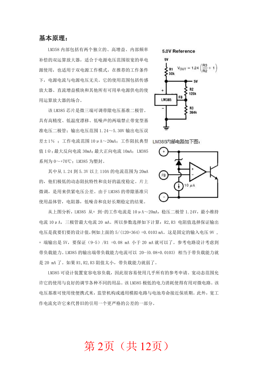
该 LM385 芯片是微三端可调带隙电压基准二极管。
具有高精度、低温度漂移、低噪声的两端禁止带宽型基
准电压二极管;输出电压范围 1.24~5.30V 输出电压误
差±1% ;工作电流范围 10μA~20mA;工作阻抗典型
值 1Ω;最大反向电流 30mA;最大正向电流 10mA; LM385
系列为 0~+70℃;LM385 为塑封。
其中从 1.24 到 5.3V 以上 110A 的电流范围为 20mA
的,他们极低的动态阻抗特性和良好的温度稳定。片上
微调,是用来供紧电压公差。由于 LM385 的带隙基准只
使用晶体管,电阻器,低噪音和良好长期稳定的结果。
从上图分析,LM385 从+ 到-的工作电流是 10μA~20mA,稳压二极管 1.24V,最小维持
电流 10μA,三极管最大电流 20 mA。所以参数选择如下计算:R2,R3 电阻值选择保证输出
电压是我要们要的设计值,例如上面的 5/(120+364) =0.0103 mA。这是固定的输入电压 9V ,
+ 端输出是 5V,要保证(9-5)/R1 =0.08 mA 小于 20 mA 就可以了。参考电路设计考虑到
带负载能力。LM385 的输出端带负载能力电流可以 20-(0.08+0.0103) 相当于带负载能力就
是 20 mA 了。如果 R1,R2,R3 阻值太小,带负载能力就弱了。
LM385 可设计装置宽容电容负载,因此很容易使用几乎所有的参考申请。宽动态范围允
许它的使用与良好的调节各种不同的用品。该 LM385 极低的电力消耗使得有用对微电路。该
电压基准可使用使便携式米,监管机构或通用模拟电路与电池寿命接近保质期。此外,宽工
作电流允许它来代替旧的引用一个更严格的公差的一部分。
第 2页(共 12页)
�
设计方案:
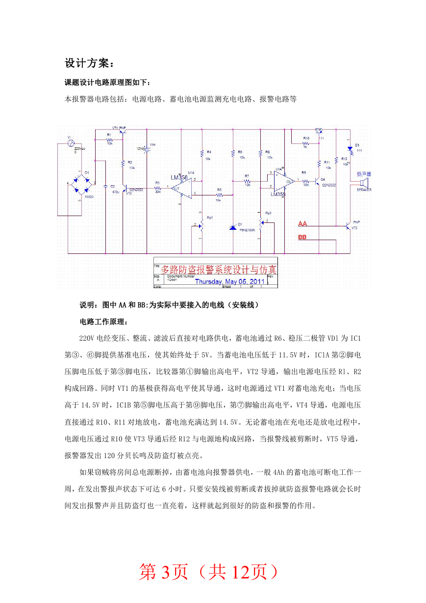
课题设计电路原理图如下:
本报警器电路包括:电源电路、蓄电池电源监测充电电路、报警电路等
说明:图中 AA 和 BB:为实际中要接入的电线(安装线)
电路工作原理:
220V 电经变压、整流、滤波后直接对电路供电,蓄电池通过 R6、稳压二极管 VDl 为 IC1
第③、⑥脚提供基准电压,使其始终处于 5V。当蓄电池电压低于 11.5V 时,IClA 第②脚电
压脚电压低于第③脚电压,比较器第①脚输出高电平,VT2 导通,输出电源电压经 Rl、R2
构成回路。同时 VT1 的基极获得高电平使其导通,这时电源通过 VT1 对蓄电池充电;当电压
高于 14.5V 时,IC1B 第⑤脚电压高于第⑨脚电压,第⑦脚输出高电平,VT4 导通,电源电压
直接通过 R10、R11 对地放电,蓄电池充满达到 14.5V。无论蓄电池在充电还是放电过程中,
电源电压通过 R10 使 VT3 导通后经 R12 与电源地构成回路,当报警线被剪断时,VT5 导通,
报警器发出 120 分贝长鸣及防盗灯被点亮。
如果窃贼将房间总电源断掉,由蓄电池向报警器供电,一般 4Ah 的蓄电池可断电工作一
周,在发出警报声状态下可达 6 小时。只要安装线被剪断或者拔掉就防盗报警电路就会长时
间发出报警声并且防盗灯也一直亮着,这样就起到很好的防盗和报警的作用。
第 3页(共 12页)
�
以下为课题设计中进行的模拟与仿真实验:
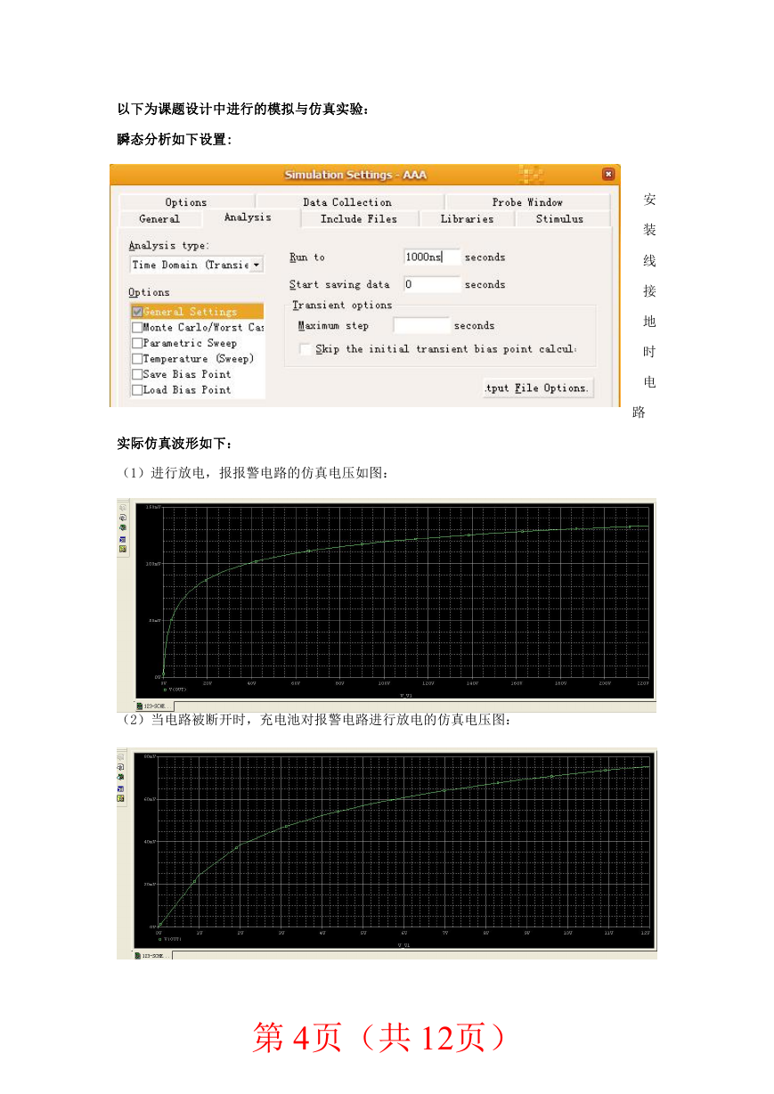
瞬态分析如下设置:
实际仿真波形如下:
(1)进行放电,报报警电路的仿真电压如图:
安
装
线
接
地
时
电
路
(2)当电路被断开时,充电池对报警电路进行放电的仿真电压图:
第 4页(共 12页)
�
课题设计分析:
当连接物体的线接地时,电路导通,报警电路这时有电流流过,会有电压,报警
灯和喇叭都会开始报警,通过仿真,把安装线接地时(物体被盗),报警电路有电流
流过,则证明电路会使比较器进行报警,与构想的相符合。
电 阻 阻 值 大 小 由 电 路 图 中 已 经 给 出 , 使 用 普 通 电 阻 即 可 。 T 选 择 5W, 220V/12V
变压器,VDl 为 5V 稳压二极管,C1 选用 50V 电解电容,IC1(集成电路)为双运放集
成电路 LM358,报警器为 12V 警笛蜂鸣器。蓄电池选用 12V 普通免维护蓄电池。调试
时,两安装线一定要短接,蓄电池暂不接上,电源亦不供电,使用可调稳压电源调至
11.5V 将电压加在蓄电池两端,调节 RPl,使 IC1(集成电路)A 第①脚刚好输出高电
平,接着调节稳压电源至 14.5V 时,调节 RP2 使 ICl(集成电路)B 第⑦脚刚好输出
高电平即可。只要安装线被切断,防盗报警电路就处于断路状态,发光二极管便会亮
且扬声器发出报警声音!
实验总结与心得体会:
此次课题设计让我明白:理想是美好的,二而实际往往与理想存在差距,理想必须和实
际相结合才有意义,即实践是检验真理的唯一标准!!!
通过本次实验,不仅仅让我有效地将课本所学的知识应用于实践,达到了学以致用的目
的,而且在设计的过程中,使自己在学习新知识﹑发现问题﹑解决问题等方面得到了很好的
锻炼,为以后的学习和工作打下了良好的基础。
总而言之,虽然本次实验设计耗费了我不少的课余时间,但是确实给我带来了不少收获,
觉得这样的课程设计是挺有意义的,挺能锻炼一个人的。
此外,通过本次实验,也进一步地熟悉了利用电路软件 ORCAD 来画电路图和模拟仿真
电路的方法。巩固了理论知识,激发了我对这个技术领域的学习激情。
同时让我懂得了课题设计的规范,步骤,及设计流程。这些现在看来似乎有点硬性和深
奥的要求,事实上却是我们以后工作中必须用到和要做到的。所以现在的练习是很有必要的。
参考文献:
实用报警电路 黄继昌主编 人民邮电出版社 2005.2
集成电路原理与应用(第二版) 谭博学 苗汇静 主编 电子工业出版版 2010.11
第 5页(共 12页)
�
附:原文部分汉译英
Design and simulation of multi-channel alarm system
(School of physics information 08-two class XXX 20081030XX)
Summary:
in life there are many valuables are basically being broke in and then cut or pulled out
of its connector and be burglarized, the project design of alarm system is based on the
principle, as long as the install line being cut or pull the alarm sound for a long time, so as to
achieve the purpose of alerting. Project design is based on the LM358 this chip, with circuit
simulation software (orCAD) principle and process modeling and simulation of burglar
alarm.
Keywords: LM358
orCAD
IC
Project background:
Alarm is robbery, theft prevention and other important facilities of accidents, in the
event of emergency, it can sound and light alarm or electronic map prompted by watch the
scene, to take prompt contingency measures. Alarm and access control systems, closed
circuit television monitoring system, visitor intercom system and electronic patrol system
together to form a security system.
Alarm system equipment is generally divided into: front-side detector,alarm controller.
Alarm controller is a host (host computer) is used to process, including wired/wireless signal
processing, fault detection of the system itself, PSU, input signal and output signal, built-in
dial-up, and the more composed, a burglar alarm system and alarm controller is essential.
Front end probes including: door contact switch, glass break detectors, infrared detectors
and infrared/microwave double mirror, emergency call button.
Burglar alarm is physically or electronic technology, automatic detection occurs in
intrusive behavior of deployment within the monitoring area, alarm signals, and secondary
prompt regional parts of the watch alarm occurs, shows possible countermeasures system.
Burglar alarm systems are important facilities to prevent looting, theft and other unexpected
events. In case of emergency, we will be able by sound and light alarm signal in a security
control centre accurately displays the scene, to take prompt contingency measures. Burglar
alarm system and access control systems, closed circuit television monitoring system, visitor
intercom system and electronic patrol system with intrusion prevention system. Burglar
alarm system typically consists of detectors (also known as the burglar alarm), transmission
channel, and alarm controller of three parts. Alarm detectors are made up of sensor and
signal processing used to detect an intruder intrusion of electronic and mechanical
components of the device,
is the core of burglar alarm systems, and sensor is a core
component of alarm detector. Sensors with different principles, can pose different types and
different uses, different detection alarm for the purpose of detection devices.
The design of the fire alarm voice alarm and disconnection alarm function, there are
small rechargeable batteries, circuit features such as reliable, secure, high performance, easy
to implement, and design in the process of further understanding of the principle and
第 6页(共 12页)
�
dual
amplifier
operational
application of comparator.
Basic principles:
LM358 including, high gain, with two separate
internal
frequency
compensation, suitable for a wide range power supply
voltages of single use, also apply to dual power mode,
under the recommended conditions of work, has nothing to
do with the power supply voltage of power supply current.
It covers the use of sensor amplifier, DC gain modules, and
other use of all available
single-supply operational
amplifier.
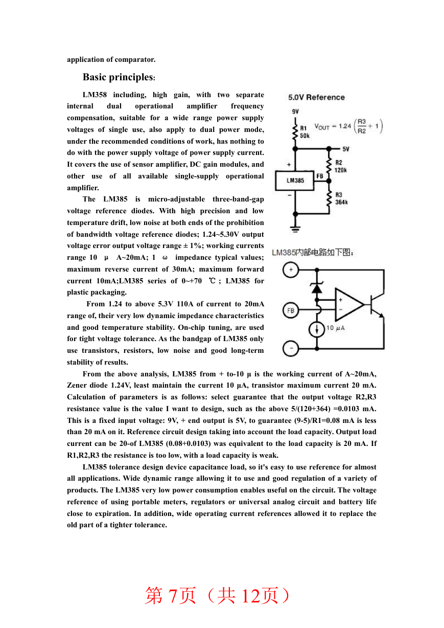
The LM385 is micro-adjustable
three-band-gap
voltage reference diodes. With high precision and low
temperature drift, low noise at both ends of the prohibition
of bandwidth voltage reference diodes; 1.24~5.30V output
voltage error output voltage range ± 1%; working currents
range 10 μ A~20mA; 1 ω impedance typical values;
maximum reverse current of 30mA; maximum forward
current 10mA;LM385 series of 0~+70 ℃ ; LM385 for
plastic packaging.
From 1.24 to above 5.3V 110A of current to 20mA
range of, their very low dynamic impedance characteristics
and good temperature stability. On-chip tuning, are used
for tight voltage tolerance. As the bandgap of LM385 only
use transistors, resistors, low noise and good long-term
stability of results.
From the above analysis, LM385 from + to-10 μ is the working current of A~20mA,
Zener diode 1.24V, least maintain the current 10 μA, transistor maximum current 20 mA.
Calculation of parameters is as follows: select guarantee that the output voltage R2,R3
resistance value is the value I want to design, such as the above 5/(120+364) =0.0103 mA.
This is a fixed input voltage: 9V, + end output is 5V, to guarantee (9-5)/R1=0.08 mA is less
than 20 mA on it. Reference circuit design taking into account the load capacity. Output load
current can be 20-of LM385 (0.08+0.0103) was equivalent to the load capacity is 20 mA. If
R1,R2,R3 the resistance is too low, with a load capacity is weak.
LM385 tolerance design device capacitance load, so it's easy to use reference for almost
all applications. Wide dynamic range allowing it to use and good regulation of a variety of
products. The LM385 very low power consumption enables useful on the circuit. The voltage
reference of using portable meters, regulators or universal analog circuit and battery life
close to expiration. In addition, wide operating current references allowed it to replace the
old part of a tighter tolerance.
第 7页(共 12页)
�
另附:LM358 芯片部分资料
第 8页(共 12页)
�


 2023年江西萍乡中考道德与法治真题及答案.doc
 2012年重庆南川中考生物真题及答案.doc
 2013年江西师范大学地理学综合及文艺理论基础考研真题.doc
 2020年四川甘孜小升初语文真题及答案I卷.doc
 2020年注册岩土工程师专业基础考试真题及答案.doc
 2023-2024学年福建省厦门市九年级上学期数学月考试题及答案.doc
 2021-2022学年辽宁省沈阳市大东区九年级上学期语文期末试题及答案.doc
 2022-2023学年北京东城区初三第一学期物理期末试卷及答案.doc
 2018上半年江西教师资格初中地理学科知识与教学能力真题及答案.doc
 2012年河北国家公务员申论考试真题及答案-省级.doc
 2020-2021学年江苏省扬州市江都区邵樊片九年级上学期数学第一次质量检测试题及答案.doc
 2022下半年黑龙江教师资格证中学综合素质真题及答案.doc