logo资料库

PCI9056详细芯片手册.pdf

第1页 / 共392页
第2页 / 共392页
第3页 / 共392页
第4页 / 共392页
第5页 / 共392页
第6页 / 共392页
第7页 / 共392页
第8页 / 共392页
资料共392页,剩余部分请下载后查看
Contents
Figures
Tables
Registers
Timing Diagrams
Preface
Feature Summary
1 Introduction
1.1 Company and Product Background
1.2 Data Pipe Architecture Technology
1.2.1 High-Speed Data Transfers
1.2.1.1 Direct Transfers
1.2.1.1.1 DirectMaster
1.2.1.1.2 DirectSlave
1.2.1.2 DMA
1.2.1.2.1 DMA Block Mode
1.2.1.2.2 DMA Scatter/Gather Mode
1.2.1.2.3 Hardware DMA Controls— EOT and Demand Mode
1.2.2 Intelligent Messaging Unit
1.3 PCI9056 I/O Accelerator
1.3.1 Applications
1.3.1.1 High-Performance Motorola MPC850 and MPC860 PowerQUICC Designs
1.3.1.2 High-Performance CompactPCI Adapter Cards
1.3.1.3 High-Performance PCI Adapter Cards
1.3.1.4 High-Performance Embedded Host Designs
1.4 Major Features
1.4.1 Interfaces
1.4.2 Data Transfer
1.4.3 Messaging Unit
1.4.4 Hosting Features
1.4.5 Electrical/Mechanical
1.4.6 Miscellaneous
1.5 Compatibility with Other PLX Chips
1.5.1 Pin Compatibility
1.5.2 Register Compatibility
1.5.3 PCI9056 Comparison with Other PLX Chips
2 M Mode Bus Operation
2.1 PCI Bus Cycles
2.1.1 DirectSlave Command Codes
2.1.2 PCI Master Command Codes
2.1.2.1 DMA Master Command Codes
2.1.2.2 DirectMaster Local-to-PCI Command Codes
2.1.3 PCI Arbitration
2.1.4 PCI Bus Wait States
2.2 Local Bus Cycles
2.2.1 Local Bus Arbitration
2.2.1.1 Local Bus Arbitration Timing Diagram
2.2.2 DirectMaster
2.2.3 DirectSlave
2.2.4 Wait State Control
2.2.4.1 Local Bus Wait States
2.2.5 Data Transfer Modes
2.2.5.1 Single Cycle Mode
2.2.5.1.1 Partial Data Accesses
2.2.5.2 Burst-4 Mode
2.2.5.2.1 Partial Data (<4 Bytes) Accesses
2.2.5.3 Continuous Burst Mode
2.2.6 Local Bus Read Accesses
2.2.7 Local Bus Write Accesses
2.2.8 DirectSlave Accesses to 8- or 16-Bit Local Bus
2.2.9 Local Bus Data Parity
2.3 Big Endian/Little Endian
2.3.1 PCI Bus Data Bits Mapping onto Local Bus
2.4 Serial EEPROM
2.4.1 PCI9056 Initialization from Serial EEPROM
2.4.2 Local Initialization and PCI Bus Behavior
2.4.2.1 Long Serial EEPROM Load
2.4.2.2 Extra Long Serial EEPROM Load
2.4.3 Serial EEPROM Access
2.4.4 Serial EEPROM Initialization Timing Diagram
2.5 Internal Register Access
2.5.1 PCI Bus Access to Internal Registers
2.5.1.1 New Capabilities Function Support
2.5.2 Local Bus Access to Internal Registers
3 M Mode Functional Description
3.1 Reset Operation
3.1.1 Adapter Mode
3.1.1.1 PCI Bus RST# Input
3.1.1.2 JTAG Reset TRST# Input
3.1.1.3 Software Reset
3.1.1.4 Power Management Reset
3.1.2 Host Mode
3.1.2.1 Local Reset
3.1.2.2 Software Reset
3.1.2.3 Power Management Reset
3.2 PCI9056 Initialization
3.3 Response to FIFO Full or Empty
3.4 Direct Data Transfer Modes
3.4.1 DirectMaster Operation (Local Master-to-PCI Slave)
3.4.1.1 DirectMaster Memory and I/O Decode
3.4.1.2 DirectMaster FIFOs
3.4.1.3 DirectMaster Memory Access
3.4.1.3.1 DirectMaster Writes
3.4.1.3.2 DirectMaster Reads
3.4.1.4 DirectMaster I/O
3.4.1.5 DirectMaster Delayed Read Mode
3.4.1.6 DirectMaster Delayed Write Mode
3.4.1.7 DirectMaster Read Ahead Mode
3.4.1.8 RETRY# Capability
3.4.1.9 DirectMaster Configuration (PCI Type 0 or Type 1 Configuration Cycles)
3.4.1.9.1 DirectMaster Configuration Cycle Example
3.4.1.10 DirectMaster PCI Dual Address Cycles
3.4.1.11 PCI Master/Target Abort
3.4.1.12 DirectMaster Memory Write and Invalidate
3.4.1.13 IDMA/SDMA Operation
3.4.1.13.1 IDMA Operation
3.4.1.13.2 SDMA Operation
3.4.2 DirectSlave Operation (PCI Master-to-Local Bus Access)
3.4.2.1 DirectSlave Writes
3.4.2.2 DirectSlave Reads
3.4.2.3 DirectSlave Lock
3.4.2.4 PCI r2.2-Compliance Enable
3.4.2.4.1 DirectSlave Delayed Read Mode
3.4.2.4.2 215 PCI Clock Timeout
3.4.2.4.3 PCI r2.2 16- and 8-Clock Rule
3.4.2.5 DirectSlave Read Ahead Mode
3.4.2.6 DirectSlave Delayed Write Mode
3.4.2.7 DirectSlave Local Bus TA# Timeout Mode
3.4.2.8 DirectSlave Transfer Error
3.4.2.9 DirectSlave PCI-to-Local Address Mapping
3.4.2.9.1 DirectSlave Local Bus Initialization
3.4.2.9.2 DirectSlave PCI Initialization
3.4.2.9.3 DirectSlave PCI Initialization Example
3.4.2.9.4 DirectSlave Transfer Size
3.4.2.10 DirectSlave Priority
3.4.3 Deadlock Conditions
3.4.3.1 Backoff
3.4.3.1.1 Software/Hardware Solution for Systems without Backoff Capability
3.4.3.1.2 Preempt Solution
3.4.3.2 Software Solutions to Deadlock
3.4.4 DMA Operation
3.4.4.1 DMA PCI Dual Address Cycles
3.4.4.2 DMA Block Mode
3.4.4.2.1 DMA Block Mode PCI Dual Address Cycles
3.4.4.3 DMA Scatter/Gather Mode
3.4.4.3.1 DMA Scatter/Gather PCI Dual Address Cycles
3.4.4.3.2 DMA Clear Count Mode
3.4.4.3.3 DMA Ring Management (Valid Mode)
3.4.4.4 DMA Memory Write and Invalidate
3.4.4.5 DMA Abort
3.4.4.6 DMA Channel Priority
3.4.4.7 DMA Channel x Interrupts
3.4.4.8 DMA Data Transfers
3.4.4.8.1 Local-to-PCI Bus DMA Transfer
3.4.4.8.2 PCI-to-Local Bus DMA Transfer
3.4.4.9 DMA Local Bus Error Condition
3.4.4.10 DMA Unaligned Transfers
3.4.4.11 DMA Demand Mode, Channel x
3.4.4.11.1 Fast Terminate Mode Operation
3.4.4.11.2 Slow Terminate Mode Operation
3.4.4.12 End of Transfer (EOT#) Input
3.4.4.13 DMA Arbitration
3.4.4.14 Local Bus DMA Priority
3.4.4.15 Local Bus Latency and Pause Timers
3.4.4.16 DMA FIFO Programmable Threshold
3.4.4.17 DMA PCI Master/Target Abort
3.5 M Mode Functional Timing Diagrams
3.5.1 Configuration Timing Diagrams
3.5.2 M Mode DirectMaster Timing Diagrams
3.5.3 M Mode DirectSlave Timing Diagrams
3.5.4 M Mode DMA Timing Diagrams
4 C and J Modes Bus Operation
4.1 PCI Bus Cycles
4.1.1 DirectSlave Command Codes
4.1.2 PCI Master Command Codes
4.1.2.1 DMA Master Command Codes
4.1.2.2 Direct Local-to-PCI Command Codes
4.1.3 PCI Arbitration
4.1.4 PCI Bus Wait States
4.2 Local Bus Cycles
4.2.1 Local Bus Arbitration and BREQi
4.2.1.1 Local Bus Arbitration Timing Diagram
4.2.2 DirectMaster
4.2.3 DirectSlave
4.2.4 Wait State Control
4.2.4.1 Local Bus Wait States
4.2.5 Data Transfer Modes
4.2.5.1 Single Cycle Mode
4.2.5.1.1 Partial Data Accesses
4.2.5.2 Burst-4 Mode
4.2.5.2.1 Partial Data (<4 Bytes) Accesses
4.2.5.3 Continuous Burst Mode
4.2.6 Recovery States (J Mode Only)
4.2.7 Local Bus Read Accesses
4.2.8 Local Bus Write Accesses
4.2.9 DirectSlave Accesses to 8- or 16-Bit Local Bus
4.2.10 Local Bus Data Parity
4.3 Big Endian/Little Endian
4.3.1 PCI Bus Data Bits Mapping onto Local Bus
4.3.2 Local Bus Big/Little Endian Mode Accesses
4.4 Serial EEPROM
4.4.1 PCI9056 Initialization from Serial EEPROM
4.4.2 Local Initialization and PCI Bus Behavior
4.4.2.1 Long Serial EEPROM Load
4.4.2.2 Extra Long Serial EEPROM Load
4.4.3 Serial EEPROM Access
4.4.4 Serial EEPROM Initialization Timing Diagram
4.5 Internal Register Access
4.5.1 PCI Bus Access to Internal Registers
4.5.1.1 New Capabilities Function Support
4.5.2 Local Bus Access to Internal Registers
5 C and J Modes Functional Description
5.1 Reset Operation
5.1.1 Adapter Mode
5.1.1.1 PCI Bus RST# Input
5.1.1.2 JTAG Reset TRST# Input
5.1.1.3 Software Reset
5.1.1.4 Power Management Reset
5.1.2 Host Mode
5.1.2.1 Local Reset
5.1.2.2 Software Reset
5.1.2.3 Power Management Reset
5.2 PCI9056 Initialization
5.3 Response to FIFO Full or Empty
5.4 Direct Data Transfer Modes
5.4.1 DirectMaster Operation (Local Master-to-PCI Slave)
5.4.1.1 DirectMaster Memory and I/O Decode
5.4.1.2 DirectMaster FIFOs
5.4.1.3 DirectMaster Memory Access
5.4.1.3.1 DirectMaster Writes
5.4.1.3.2 DirectMaster Reads
5.4.1.4 DirectMaster I/O
5.4.1.5 DirectMaster Delayed Write Mode
5.4.1.6 DirectMaster Read Ahead Mode
5.4.1.7 DirectMaster Configuration (PCI Type 0 or Type 1 Configuration Cycles)
5.4.1.7.1 DirectMaster Configuration Cycle Example
5.4.1.8 DirectMaster PCI Dual Address Cycles
5.4.1.9 PCI Master/Target Abort
5.4.1.10 DirectMaster Memory Write and Invalidate
5.4.1.11 DirectMaster Write FIFO Programmable Almost Full, DMPAF Flag
5.4.2 DirectSlave Operation (PCI Master-to-Local Bus Access)
5.4.2.1 DirectSlave Writes
5.4.2.2 DirectSlave Reads
5.4.2.3 DirectSlave Lock
5.4.2.4 PCI Compliance Enable
5.4.2.4.1 DirectSlave Delayed Read Mode
5.4.2.4.2 215 PCI Clock Timeout
5.4.2.4.3 PCI r2.2 16- and 8-Clock Rule
5.4.2.5 DirectSlave Read Ahead Mode
5.4.2.6 DirectSlave Delayed Write Mode
5.4.2.7 DirectSlave Local Bus READY# Timeout Mode
5.4.2.8 DirectSlave Transfer Error
5.4.2.9 DirectSlave PCI-to-Local Address Mapping
5.4.2.9.1 DirectSlave Local Bus Initialization
5.4.2.9.2 DirectSlave PCI Initialization
5.4.2.9.3 DirectSlave PCI Initialization Example
5.4.2.9.4 DirectSlave Byte Enables (C Mode)
5.4.2.9.5 DirectSlave Byte Enables (J Mode)
5.4.2.10 DirectSlave Priority
5.4.3 Deadlock Conditions
5.4.3.1 Backoff
5.4.3.1.1 Software/Hardware Solution for Systems without Backoff Capability
5.4.3.1.2 Preempt Solution
5.4.3.2 Software Solutions to Deadlock
5.4.4 DMA Operation
5.4.4.1 DMA PCI Dual Address Cycles
5.4.4.2 DMA Block Mode
5.4.4.2.1 DMA Block Mode PCI Dual Address Cycles
5.4.4.3 DMA Scatter/Gather Mode
5.4.4.3.1 DMA Scatter/Gather PCI Dual Address Cycle
5.4.4.3.2 DMA Clear Count Mode
5.4.4.3.3 DMA Ring Management (ValidMode)
5.4.4.4 DMA Memory Write and Invalidate
5.4.4.5 DMA Abort
5.4.4.6 DMA Channel Priority
5.4.4.7 DMA Channel x Interrupts
5.4.4.8 DMA Data Transfers
5.4.4.8.1 Local-to-PCI Bus DMA Transfer
5.4.4.8.2 PCI-to-Local Bus DMA Transfer
5.4.4.9 DMA Unaligned Transfers
5.4.4.10 DMA Demand Mode, Channel x
5.4.4.10.1 Fast Terminate Mode Operation
5.4.4.10.2 Slow Terminate Mode Operation
5.4.4.11 End of Transfer (EOT#) Input
5.4.4.12 DMA Arbitration
5.4.4.13 Local Bus DMA Priority
5.4.4.14 Local Bus Latency and Pause Timers
5.4.4.15 DMA FIFO Programmable Threshold
5.4.4.16 DMA PCI Master/Target Abort
5.5 C and J Modes Functional Timing Diagrams
5.5.1 Configuration Timing Diagrams
5.6 C Mode Functional Timing Diagrams
5.6.1 C Mode DirectMaster Timing Diagrams
5.6.2 C Mode DirectSlave Timing Diagrams
5.6.3 C Mode DMA Timing Diagrams
5.7 J Mode Functional Timing Diagrams
5.7.1 J Mode DirectMaster Timing Diagrams
5.7.2 J Mode DirectSlave Timing Diagrams
5.7.3 J Mode DMA Timing Diagrams
6 Interrupts, User I/O, and IDDQEN#
6.1 Interrupts
6.1.1 PCI Interrupts (INTA#)
6.1.2 Local Interrupt Input (LINTi#)
6.1.3 Local Interrupt Output (LINTo#)
6.1.4 PCI Master/Target Abort Interrupt
6.1.5 Mailbox Registers
6.1.6 Doorbell Registers
6.1.6.1 Local-to-PCI Doorbell Interrupt
6.1.6.1.1 M Mode Local-to-PCI Doorbell Interrupt
6.1.6.1.2 C and J Modes Local-to-PCI Doorbell Interrupt
6.1.6.2 PCI-to-Local Doorbell Interrupt
6.1.7 Built-In Self-Test Interrupt (BIST)
6.1.8 DMA Channel x Interrupts
6.1.9 All Modes PCI SERR# (PCI NMI)
6.1.10 M Mode PCI SERR#
6.1.11 All Modes PCI PERR# (PCI Parity Error)
6.1.12 M Mode Local Bus TEA# Signal
6.1.13 C and J Modes Local LSERR# (Local NMI)
6.1.14 Interrupt Timing Diagram
6.2 User I/O
6.3 IDDQEN# Multi-Function Shared Pin—Power-On Function
7 Intelligent I/O (I2O)
7.1 I2O-Compatible Messaging Unit
7.1.1 Inbound Messages
7.1.2 Outbound Messages
7.1.3 I2O Pointer Management
7.1.4 Inbound Free List FIFO
7.1.5 Inbound Post Queue FIFO
7.1.6 Outbound Post Queue FIFO
7.1.7 Outbound Post Queue
7.1.8 Inbound Free Queue
7.1.9 Outbound Free List FIFO
7.1.10 I2O Enable Sequence
8 PCI Power Management
8.1 Overview
8.1.1 PCI Power Management Functional Description
8.1.2 66 MHz PCI Clock D2 Power State Support
8.1.3 D3cold Power State Support
8.1.4 System Changes Power Mode Example
8.1.5 Non-D3cold Wake-Up Request Example
9 CompactPCI Hot Swap
9.1 Overview
9.1.1 Silicon Behavior during Initialization on PCI Bus
9.1.2 Configuration
9.2 Controlling Connection Processes
9.2.1 Connection Control
9.2.1.1 Board Slot Control
9.2.1.2 Board Healthy
9.2.1.3 Platform Reset
9.2.2 Software Connection Control
9.2.2.1 Ejector Switch and Blue Status LED
9.2.2.2 ENUM#
9.2.2.3 Hot Swap Control/Status Register (HS_CSR)
9.2.2.4 Hot Swap Capabilities Register
10 PCI Vital Product Data (VPD)
10.1 Overview
10.2 VPD Capabilities Registers
10.2.1 VPD Control Register
10.2.2 VPD Data Register
10.3 VPD Serial EEPROM Partitioning
10.4 Sequential Read-Only
10.5 Random Read and Write
11 Registers
11.1 Summary of Register Differences
11.2 Register Address Mapping
11.3 PCI Configuration Registers
11.4 Local Configuration Registers
11.5 Runtime Registers
11.6 DMA Registers
11.7 Messaging Queue (I2O) Registers
12 Pin Description
12.1 Pin Summary
12.2 Pull-Up and Pull-Down Resistors
12.3 Pinout Common to All Bus Modes
12.4 M Bus Mode Pinout
12.5 C Bus Mode Pinout
12.6 J Bus Mode Pinout
12.7 JTAG Interface
12.7.1 IEEE 1149.1 Test Access Port
12.7.2 JTAG Instructions
12.7.3 JTAG Boundary Scan
12.7.4 JTAG Reset Input TRST#
13 Electrical Specifications
13.1 3.3 and 5V Mixed-Voltage Devices and Power Sequence
13.2 General Electrical Specifications
13.3 Local Inputs
13.4 Local Outputs
13.5 ALE Output Delay Timing for All Local Bus Clock Rates
14 Physical Specifications
14.1 Mechanical Dimensions
14.2 Ball Grid Assignments
A General Information
A.1 Ordering Instructions
A.2 United States and International Representatives, and Distributors
A.3 Technical Support
Index
A
B
C
D
E
F
G
H
I
J
L
M
N
O
P
Q
R
S
T
U
V
W
Z
PCI 9056BA Data Book
PCI 9056BA Data Book Version 1.1 October 2003 Website: Technical Support: Phone: Fax: http://www.plxtech.com http://www.plxtech.com/support/ 408 774-9060 800 759-3735 408 774-2169
© 2003 PLX Technology, Inc. All rights reserved. PLX Technology, Inc., retains the right to make changes to this product at any time, without notice. Products may have minor variations to this publication, known as errata. PLX assumes no liability whatsoever, including infringement of any patent or copyright, for sale and use of PLX products. PLX Technology, the PLX logo, and Data Pipe Architecture are registered trademarks of PLX Technology, Inc. Other brands and names are the property of their respective owners. Order Number: 9056BA-SIL-DB-P1-1.1 Printed in the USA, October 2003
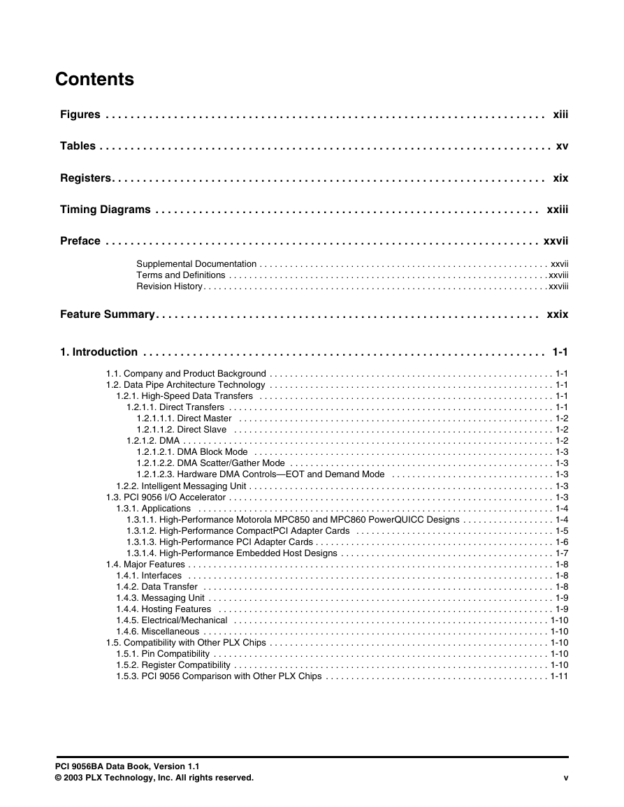
Contents Figures . . . . . . . . . . . . . . . . . . . . . . . . . . . . . . . . . . . . . . . . . . . . . . . . . . . . . . . . . . . . . . . . . . . . . . . xiii Tables . . . . . . . . . . . . . . . . . . . . . . . . . . . . . . . . . . . . . . . . . . . . . . . . . . . . . . . . . . . . . . . . . . . . . . . . . xv Registers. . . . . . . . . . . . . . . . . . . . . . . . . . . . . . . . . . . . . . . . . . . . . . . . . . . . . . . . . . . . . . . . . . . . . . xix Timing Diagrams . . . . . . . . . . . . . . . . . . . . . . . . . . . . . . . . . . . . . . . . . . . . . . . . . . . . . . . . . . . . . . xxiii Preface . . . . . . . . . . . . . . . . . . . . . . . . . . . . . . . . . . . . . . . . . . . . . . . . . . . . . . . . . . . . . . . . . . . . . . xxvii Supplemental Documentation . . . . . . . . . . . . . . . . . . . . . . . . . . . . . . . . . . . . . . . . . . . . . . . . . . . . . . . . . xxvii Terms and Definitions . . . . . . . . . . . . . . . . . . . . . . . . . . . . . . . . . . . . . . . . . . . . . . . . . . . . . . . . . . . . . . . xxviii Revision History. . . . . . . . . . . . . . . . . . . . . . . . . . . . . . . . . . . . . . . . . . . . . . . . . . . . . . . . . . . . . . . . . . . . xxviii Feature Summary. . . . . . . . . . . . . . . . . . . . . . . . . . . . . . . . . . . . . . . . . . . . . . . . . . . . . . . . . . . . . . xxix 1. Introduction . . . . . . . . . . . . . . . . . . . . . . . . . . . . . . . . . . . . . . . . . . . . . . . . . . . . . . . . . . . . . . . . . 1-1 1.1. Company and Product Background . . . . . . . . . . . . . . . . . . . . . . . . . . . . . . . . . . . . . . . . . . . . . . . . . . . . . . . . 1-1 1.2. Data Pipe Architecture Technology . . . . . . . . . . . . . . . . . . . . . . . . . . . . . . . . . . . . . . . . . . . . . . . . . . . . . . . . 1-1 1.2.1. High-Speed Data Transfers . . . . . . . . . . . . . . . . . . . . . . . . . . . . . . . . . . . . . . . . . . . . . . . . . . . . . . . . . . 1-1 1.2.1.1. Direct Transfers . . . . . . . . . . . . . . . . . . . . . . . . . . . . . . . . . . . . . . . . . . . . . . . . . . . . . . . . . . . . . . . . 1-1 1.2.1.1.1. Direct Master . . . . . . . . . . . . . . . . . . . . . . . . . . . . . . . . . . . . . . . . . . . . . . . . . . . . . . . . . . . . . . 1-2 1.2.1.1.2. Direct Slave . . . . . . . . . . . . . . . . . . . . . . . . . . . . . . . . . . . . . . . . . . . . . . . . . . . . . . . . . . . . . . . 1-2 1.2.1.2. DMA . . . . . . . . . . . . . . . . . . . . . . . . . . . . . . . . . . . . . . . . . . . . . . . . . . . . . . . . . . . . . . . . . . . . . . . . . 1-2 1.2.1.2.1. DMA Block Mode . . . . . . . . . . . . . . . . . . . . . . . . . . . . . . . . . . . . . . . . . . . . . . . . . . . . . . . . . . . 1-3 1.2.1.2.2. DMA Scatter/Gather Mode . . . . . . . . . . . . . . . . . . . . . . . . . . . . . . . . . . . . . . . . . . . . . . . . . . . . 1-3 1.2.1.2.3. Hardware DMA Controls—EOT and Demand Mode . . . . . . . . . . . . . . . . . . . . . . . . . . . . . . . . 1-3 1.2.2. Intelligent Messaging Unit . . . . . . . . . . . . . . . . . . . . . . . . . . . . . . . . . . . . . . . . . . . . . . . . . . . . . . . . . . . . 1-3 1.3. PCI 9056 I/O Accelerator . . . . . . . . . . . . . . . . . . . . . . . . . . . . . . . . . . . . . . . . . . . . . . . . . . . . . . . . . . . . . . . . 1-3 1.3.1. Applications . . . . . . . . . . . . . . . . . . . . . . . . . . . . . . . . . . . . . . . . . . . . . . . . . . . . . . . . . . . . . . . . . . . . . . 1-4 1.3.1.1. High-Performance Motorola MPC850 and MPC860 PowerQUICC Designs . . . . . . . . . . . . . . . . . . 1-4 1.3.1.2. High-Performance CompactPCI Adapter Cards . . . . . . . . . . . . . . . . . . . . . . . . . . . . . . . . . . . . . . . 1-5 1.3.1.3. High-Performance PCI Adapter Cards . . . . . . . . . . . . . . . . . . . . . . . . . . . . . . . . . . . . . . . . . . . . . . . 1-6 1.3.1.4. High-Performance Embedded Host Designs . . . . . . . . . . . . . . . . . . . . . . . . . . . . . . . . . . . . . . . . . . 1-7 1.4. Major Features . . . . . . . . . . . . . . . . . . . . . . . . . . . . . . . . . . . . . . . . . . . . . . . . . . . . . . . . . . . . . . . . . . . . . . . . 1-8 1.4.1. Interfaces . . . . . . . . . . . . . . . . . . . . . . . . . . . . . . . . . . . . . . . . . . . . . . . . . . . . . . . . . . . . . . . . . . . . . . . . 1-8 1.4.2. Data Transfer . . . . . . . . . . . . . . . . . . . . . . . . . . . . . . . . . . . . . . . . . . . . . . . . . . . . . . . . . . . . . . . . . . . . . 1-8 1.4.3. Messaging Unit . . . . . . . . . . . . . . . . . . . . . . . . . . . . . . . . . . . . . . . . . . . . . . . . . . . . . . . . . . . . . . . . . . . . 1-9 1.4.4. Hosting Features . . . . . . . . . . . . . . . . . . . . . . . . . . . . . . . . . . . . . . . . . . . . . . . . . . . . . . . . . . . . . . . . . . 1-9 1.4.5. Electrical/Mechanical . . . . . . . . . . . . . . . . . . . . . . . . . . . . . . . . . . . . . . . . . . . . . . . . . . . . . . . . . . . . . . 1-10 1.4.6. Miscellaneous . . . . . . . . . . . . . . . . . . . . . . . . . . . . . . . . . . . . . . . . . . . . . . . . . . . . . . . . . . . . . . . . . . . . 1-10 1.5. Compatibility with Other PLX Chips . . . . . . . . . . . . . . . . . . . . . . . . . . . . . . . . . . . . . . . . . . . . . . . . . . . . . . . 1-10 1.5.1. Pin Compatibility . . . . . . . . . . . . . . . . . . . . . . . . . . . . . . . . . . . . . . . . . . . . . . . . . . . . . . . . . . . . . . . . . . 1-10 1.5.2. Register Compatibility . . . . . . . . . . . . . . . . . . . . . . . . . . . . . . . . . . . . . . . . . . . . . . . . . . . . . . . . . . . . . . 1-10 1.5.3. PCI 9056 Comparison with Other PLX Chips . . . . . . . . . . . . . . . . . . . . . . . . . . . . . . . . . . . . . . . . . . . . 1-11 PCI 9056BA Data Book, Version 1.1 © 2003 PLX Technology, Inc. All rights reserved. v
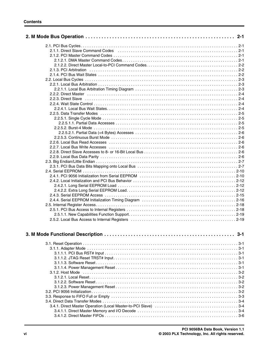
Contents 2. M Mode Bus Operation . . . . . . . . . . . . . . . . . . . . . . . . . . . . . . . . . . . . . . . . . . . . . . . . . . . . . . . . 2-1 2.1. PCI Bus Cycles. . . . . . . . . . . . . . . . . . . . . . . . . . . . . . . . . . . . . . . . . . . . . . . . . . . . . . . . . . . . . . . . . . . . . . . . 2-1 2.1.1. Direct Slave Command Codes . . . . . . . . . . . . . . . . . . . . . . . . . . . . . . . . . . . . . . . . . . . . . . . . . . . . . . . 2-1 2.1.2. PCI Master Command Codes . . . . . . . . . . . . . . . . . . . . . . . . . . . . . . . . . . . . . . . . . . . . . . . . . . . . . . . . . 2-1 2.1.2.1. DMA Master Command Codes. . . . . . . . . . . . . . . . . . . . . . . . . . . . . . . . . . . . . . . . . . . . . . . . . . . . . 2-1 2.1.2.2. Direct Master Local-to-PCI Command Codes. . . . . . . . . . . . . . . . . . . . . . . . . . . . . . . . . . . . . . . . . . 2-2 2.1.3. PCI Arbitration . . . . . . . . . . . . . . . . . . . . . . . . . . . . . . . . . . . . . . . . . . . . . . . . . . . . . . . . . . . . . . . . . . . . 2-2 2.1.4. PCI Bus Wait States . . . . . . . . . . . . . . . . . . . . . . . . . . . . . . . . . . . . . . . . . . . . . . . . . . . . . . . . . . . . . . . . 2-2 2.2. Local Bus Cycles . . . . . . . . . . . . . . . . . . . . . . . . . . . . . . . . . . . . . . . . . . . . . . . . . . . . . . . . . . . . . . . . . . . . . . 2-3 2.2.1. Local Bus Arbitration . . . . . . . . . . . . . . . . . . . . . . . . . . . . . . . . . . . . . . . . . . . . . . . . . . . . . . . . . . . . . . . . 2-3 2.2.1.1. Local Bus Arbitration Timing Diagram . . . . . . . . . . . . . . . . . . . . . . . . . . . . . . . . . . . . . . . . . . . . . . . 2-3 2.2.2. Direct Master . . . . . . . . . . . . . . . . . . . . . . . . . . . . . . . . . . . . . . . . . . . . . . . . . . . . . . . . . . . . . . . . . . . . . 2-4 2.2.3. Direct Slave . . . . . . . . . . . . . . . . . . . . . . . . . . . . . . . . . . . . . . . . . . . . . . . . . . . . . . . . . . . . . . . . . . . . . . 2-4 2.2.4. Wait State Control . . . . . . . . . . . . . . . . . . . . . . . . . . . . . . . . . . . . . . . . . . . . . . . . . . . . . . . . . . . . . . . . . . 2-4 2.2.4.1. Local Bus Wait States. . . . . . . . . . . . . . . . . . . . . . . . . . . . . . . . . . . . . . . . . . . . . . . . . . . . . . . . . . . . 2-4 2.2.5. Data Transfer Modes . . . . . . . . . . . . . . . . . . . . . . . . . . . . . . . . . . . . . . . . . . . . . . . . . . . . . . . . . . . . . . . 2-5 2.2.5.1. Single Cycle Mode . . . . . . . . . . . . . . . . . . . . . . . . . . . . . . . . . . . . . . . . . . . . . . . . . . . . . . . . . . . . . . 2-5 2.2.5.1.1. Partial Data Accesses . . . . . . . . . . . . . . . . . . . . . . . . . . . . . . . . . . . . . . . . . . . . . . . . . . . . . . . . 2-5 2.2.5.2. Burst-4 Mode . . . . . . . . . . . . . . . . . . . . . . . . . . . . . . . . . . . . . . . . . . . . . . . . . . . . . . . . . . . . . . . . . . 2-5 2.2.5.2.1. Partial Data (<4 Bytes) Accesses . . . . . . . . . . . . . . . . . . . . . . . . . . . . . . . . . . . . . . . . . . . . . . . 2-6 2.2.5.3. Continuous Burst Mode . . . . . . . . . . . . . . . . . . . . . . . . . . . . . . . . . . . . . . . . . . . . . . . . . . . . . . . . . . 2-6 2.2.6. Local Bus Read Accesses . . . . . . . . . . . . . . . . . . . . . . . . . . . . . . . . . . . . . . . . . . . . . . . . . . . . . . . . . . . 2-6 2.2.7. Local Bus Write Accesses . . . . . . . . . . . . . . . . . . . . . . . . . . . . . . . . . . . . . . . . . . . . . . . . . . . . . . . . . . . 2-6 2.2.8. Direct Slave Accesses to 8- or 16-Bit Local Bus . . . . . . . . . . . . . . . . . . . . . . . . . . . . . . . . . . . . . . . . . . . 2-6 2.2.9. Local Bus Data Parity . . . . . . . . . . . . . . . . . . . . . . . . . . . . . . . . . . . . . . . . . . . . . . . . . . . . . . . . . . . . . . . 2-6 2.3. Big Endian/Little Endian . . . . . . . . . . . . . . . . . . . . . . . . . . . . . . . . . . . . . . . . . . . . . . . . . . . . . . . . . . . . . . . . . 2-7 2.3.1. PCI Bus Data Bits Mapping onto Local Bus . . . . . . . . . . . . . . . . . . . . . . . . . . . . . . . . . . . . . . . . . . . . . . 2-7 2.4. Serial EEPROM . . . . . . . . . . . . . . . . . . . . . . . . . . . . . . . . . . . . . . . . . . . . . . . . . . . . . . . . . . . . . . . . . . . . . . 2-10 2.4.1. PCI 9056 Initialization from Serial EEPROM . . . . . . . . . . . . . . . . . . . . . . . . . . . . . . . . . . . . . . . . . . . . 2-10 2.4.2. Local Initialization and PCI Bus Behavior . . . . . . . . . . . . . . . . . . . . . . . . . . . . . . . . . . . . . . . . . . . . . . . 2-12 2.4.2.1. Long Serial EEPROM Load . . . . . . . . . . . . . . . . . . . . . . . . . . . . . . . . . . . . . . . . . . . . . . . . . . . . . . 2-12 2.4.2.2. Extra Long Serial EEPROM Load. . . . . . . . . . . . . . . . . . . . . . . . . . . . . . . . . . . . . . . . . . . . . . . . . . 2-12 2.4.3. Serial EEPROM Access . . . . . . . . . . . . . . . . . . . . . . . . . . . . . . . . . . . . . . . . . . . . . . . . . . . . . . . . . . . . 2-15 2.4.4. Serial EEPROM Initialization Timing Diagram . . . . . . . . . . . . . . . . . . . . . . . . . . . . . . . . . . . . . . . . . . . 2-16 2.5. Internal Register Access. . . . . . . . . . . . . . . . . . . . . . . . . . . . . . . . . . . . . . . . . . . . . . . . . . . . . . . . . . . . . . . . 2-18 2.5.1. PCI Bus Access to Internal Registers . . . . . . . . . . . . . . . . . . . . . . . . . . . . . . . . . . . . . . . . . . . . . . . . . . 2-18 2.5.1.1. New Capabilities Function Support. . . . . . . . . . . . . . . . . . . . . . . . . . . . . . . . . . . . . . . . . . . . . . . . . 2-19 2.5.2. Local Bus Access to Internal Registers . . . . . . . . . . . . . . . . . . . . . . . . . . . . . . . . . . . . . . . . . . . . . . . . 2-19 3. M Mode Functional Description . . . . . . . . . . . . . . . . . . . . . . . . . . . . . . . . . . . . . . . . . . . . . . . . . 3-1 3.1. Reset Operation . . . . . . . . . . . . . . . . . . . . . . . . . . . . . . . . . . . . . . . . . . . . . . . . . . . . . . . . . . . . . . . . . . . . . . . 3-1 3.1.1. Adapter Mode . . . . . . . . . . . . . . . . . . . . . . . . . . . . . . . . . . . . . . . . . . . . . . . . . . . . . . . . . . . . . . . . . . . . . 3-1 3.1.1.1. PCI Bus RST# Input . . . . . . . . . . . . . . . . . . . . . . . . . . . . . . . . . . . . . . . . . . . . . . . . . . . . . . . . . . . . . 3-1 3.1.1.2. JTAG Reset TRST# Input. . . . . . . . . . . . . . . . . . . . . . . . . . . . . . . . . . . . . . . . . . . . . . . . . . . . . . . . . 3-1 3.1.1.3. Software Reset . . . . . . . . . . . . . . . . . . . . . . . . . . . . . . . . . . . . . . . . . . . . . . . . . . . . . . . . . . . . . . . . . 3-1 3.1.1.4. Power Management Reset . . . . . . . . . . . . . . . . . . . . . . . . . . . . . . . . . . . . . . . . . . . . . . . . . . . . . . . . 3-1 3.1.2. Host Mode . . . . . . . . . . . . . . . . . . . . . . . . . . . . . . . . . . . . . . . . . . . . . . . . . . . . . . . . . . . . . . . . . . . . . . . 3-2 3.1.2.1. Local Reset. . . . . . . . . . . . . . . . . . . . . . . . . . . . . . . . . . . . . . . . . . . . . . . . . . . . . . . . . . . . . . . . . . . . 3-2 3.1.2.2. Software Reset . . . . . . . . . . . . . . . . . . . . . . . . . . . . . . . . . . . . . . . . . . . . . . . . . . . . . . . . . . . . . . . . . 3-2 3.1.2.3. Power Management Reset . . . . . . . . . . . . . . . . . . . . . . . . . . . . . . . . . . . . . . . . . . . . . . . . . . . . . . . . 3-2 3.2. PCI 9056 Initialization . . . . . . . . . . . . . . . . . . . . . . . . . . . . . . . . . . . . . . . . . . . . . . . . . . . . . . . . . . . . . . . . . . . 3-2 3.3. Response to FIFO Full or Empty . . . . . . . . . . . . . . . . . . . . . . . . . . . . . . . . . . . . . . . . . . . . . . . . . . . . . . . . . . 3-3 3.4. Direct Data Transfer Modes . . . . . . . . . . . . . . . . . . . . . . . . . . . . . . . . . . . . . . . . . . . . . . . . . . . . . . . . . . . . . . 3-4 3.4.1. Direct Master Operation (Local Master-to-PCI Slave) . . . . . . . . . . . . . . . . . . . . . . . . . . . . . . . . . . . . . . 3-4 3.4.1.1. Direct Master Memory and I/O Decode . . . . . . . . . . . . . . . . . . . . . . . . . . . . . . . . . . . . . . . . . . . . . . 3-4 3.4.1.2. Direct Master FIFOs . . . . . . . . . . . . . . . . . . . . . . . . . . . . . . . . . . . . . . . . . . . . . . . . . . . . . . . . . . . . . 3-6 vi PCI 9056BA Data Book, Version 1.1 © 2003 PLX Technology, Inc. All rights reserved.
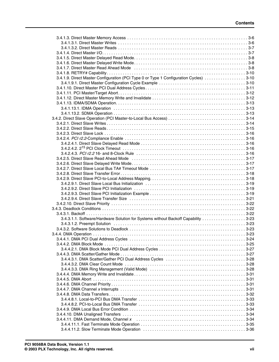
Contents 3.4.1.3. Direct Master Memory Access . . . . . . . . . . . . . . . . . . . . . . . . . . . . . . . . . . . . . . . . . . . . . . . . . . . . . 3-6 3.4.1.3.1. Direct Master Writes . . . . . . . . . . . . . . . . . . . . . . . . . . . . . . . . . . . . . . . . . . . . . . . . . . . . . . . . . 3-6 3.4.1.3.2. Direct Master Reads . . . . . . . . . . . . . . . . . . . . . . . . . . . . . . . . . . . . . . . . . . . . . . . . . . . . . . . . . 3-7 3.4.1.4. Direct Master I/O. . . . . . . . . . . . . . . . . . . . . . . . . . . . . . . . . . . . . . . . . . . . . . . . . . . . . . . . . . . . . . . . 3-7 3.4.1.5. Direct Master Delayed Read Mode. . . . . . . . . . . . . . . . . . . . . . . . . . . . . . . . . . . . . . . . . . . . . . . . . . 3-8 3.4.1.6. Direct Master Delayed Write Mode. . . . . . . . . . . . . . . . . . . . . . . . . . . . . . . . . . . . . . . . . . . . . . . . . . 3-8 3.4.1.7. Direct Master Read Ahead Mode . . . . . . . . . . . . . . . . . . . . . . . . . . . . . . . . . . . . . . . . . . . . . . . . . . 3-8 3.4.1.8. RETRY# Capability. . . . . . . . . . . . . . . . . . . . . . . . . . . . . . . . . . . . . . . . . . . . . . . . . . . . . . . . . . . . . 3-10 3.4.1.9. Direct Master Configuration (PCI Type 0 or Type 1 Configuration Cycles) . . . . . . . . . . . . . . . . . . 3-10 3.4.1.9.1. Direct Master Configuration Cycle Example . . . . . . . . . . . . . . . . . . . . . . . . . . . . . . . . . . . . . . 3-10 3.4.1.10. Direct Master PCI Dual Address Cycles . . . . . . . . . . . . . . . . . . . . . . . . . . . . . . . . . . . . . . . . . . . . 3-11 3.4.1.11. PCI Master/Target Abort. . . . . . . . . . . . . . . . . . . . . . . . . . . . . . . . . . . . . . . . . . . . . . . . . . . . . . . . 3-12 3.4.1.12. Direct Master Memory Write and Invalidate . . . . . . . . . . . . . . . . . . . . . . . . . . . . . . . . . . . . . . . . . 3-12 3.4.1.13. IDMA/SDMA Operation. . . . . . . . . . . . . . . . . . . . . . . . . . . . . . . . . . . . . . . . . . . . . . . . . . . . . . . . . 3-13 3.4.1.13.1. IDMA Operation . . . . . . . . . . . . . . . . . . . . . . . . . . . . . . . . . . . . . . . . . . . . . . . . . . . . . . . . . . 3-13 3.4.1.13.2. SDMA Operation . . . . . . . . . . . . . . . . . . . . . . . . . . . . . . . . . . . . . . . . . . . . . . . . . . . . . . . . . . 3-13 3.4.2. Direct Slave Operation (PCI Master-to-Local Bus Access) . . . . . . . . . . . . . . . . . . . . . . . . . . . . . . . . . . 3-14 3.4.2.1. Direct Slave Writes . . . . . . . . . . . . . . . . . . . . . . . . . . . . . . . . . . . . . . . . . . . . . . . . . . . . . . . . . . . . . 3-14 3.4.2.2. Direct Slave Reads . . . . . . . . . . . . . . . . . . . . . . . . . . . . . . . . . . . . . . . . . . . . . . . . . . . . . . . . . . . . . 3-15 3.4.2.3. Direct Slave Lock . . . . . . . . . . . . . . . . . . . . . . . . . . . . . . . . . . . . . . . . . . . . . . . . . . . . . . . . . . . . . . 3-16 3.4.2.4. PCI r2.2-Compliance Enable . . . . . . . . . . . . . . . . . . . . . . . . . . . . . . . . . . . . . . . . . . . . . . . . . . . . . 3-16 3.4.2.4.1. Direct Slave Delayed Read Mode . . . . . . . . . . . . . . . . . . . . . . . . . . . . . . . . . . . . . . . . . . . . . . 3-16 3.4.2.4.2. 215 PCI Clock Timeout . . . . . . . . . . . . . . . . . . . . . . . . . . . . . . . . . . . . . . . . . . . . . . . . . . . . . . 3-16 3.4.2.4.3. PCI r2.2 16- and 8-Clock Rule . . . . . . . . . . . . . . . . . . . . . . . . . . . . . . . . . . . . . . . . . . . . . . . . 3-16 3.4.2.5. Direct Slave Read Ahead Mode . . . . . . . . . . . . . . . . . . . . . . . . . . . . . . . . . . . . . . . . . . . . . . . . . . 3-17 3.4.2.6. Direct Slave Delayed Write Mode. . . . . . . . . . . . . . . . . . . . . . . . . . . . . . . . . . . . . . . . . . . . . . . . . . 3-17 3.4.2.7. Direct Slave Local Bus TA# Timeout Mode . . . . . . . . . . . . . . . . . . . . . . . . . . . . . . . . . . . . . . . . . . 3-17 3.4.2.8. Direct Slave Transfer Error . . . . . . . . . . . . . . . . . . . . . . . . . . . . . . . . . . . . . . . . . . . . . . . . . . . . . . . 3-18 3.4.2.9. Direct Slave PCI-to-Local Address Mapping. . . . . . . . . . . . . . . . . . . . . . . . . . . . . . . . . . . . . . . . . . 3-18 3.4.2.9.1. Direct Slave Local Bus Initialization . . . . . . . . . . . . . . . . . . . . . . . . . . . . . . . . . . . . . . . . . . . . 3-19 3.4.2.9.2. Direct Slave PCI Initialization . . . . . . . . . . . . . . . . . . . . . . . . . . . . . . . . . . . . . . . . . . . . . . . . . 3-19 3.4.2.9.3. Direct Slave PCI Initialization Example . . . . . . . . . . . . . . . . . . . . . . . . . . . . . . . . . . . . . . . . . . 3-19 3.4.2.9.4. Direct Slave Transfer Size . . . . . . . . . . . . . . . . . . . . . . . . . . . . . . . . . . . . . . . . . . . . . . . . . . . 3-21 3.4.2.10. Direct Slave Priority . . . . . . . . . . . . . . . . . . . . . . . . . . . . . . . . . . . . . . . . . . . . . . . . . . . . . . . . . . . 3-22 3.4.3. Deadlock Conditions . . . . . . . . . . . . . . . . . . . . . . . . . . . . . . . . . . . . . . . . . . . . . . . . . . . . . . . . . . . . . . . 3-22 3.4.3.1. Backoff . . . . . . . . . . . . . . . . . . . . . . . . . . . . . . . . . . . . . . . . . . . . . . . . . . . . . . . . . . . . . . . . . . . . . . 3-22 3.4.3.1.1. Software/Hardware Solution for Systems without Backoff Capability . . . . . . . . . . . . . . . . . . . 3-23 3.4.3.1.2. Preempt Solution . . . . . . . . . . . . . . . . . . . . . . . . . . . . . . . . . . . . . . . . . . . . . . . . . . . . . . . . . . 3-23 3.4.3.2. Software Solutions to Deadlock . . . . . . . . . . . . . . . . . . . . . . . . . . . . . . . . . . . . . . . . . . . . . . . . . . . 3-23 3.4.4. DMA Operation . . . . . . . . . . . . . . . . . . . . . . . . . . . . . . . . . . . . . . . . . . . . . . . . . . . . . . . . . . . . . . . . . . . 3-23 3.4.4.1. DMA PCI Dual Address Cycles . . . . . . . . . . . . . . . . . . . . . . . . . . . . . . . . . . . . . . . . . . . . . . . . . . . 3-24 3.4.4.2. DMA Block Mode . . . . . . . . . . . . . . . . . . . . . . . . . . . . . . . . . . . . . . . . . . . . . . . . . . . . . . . . . . . . . . 3-25 3.4.4.2.1. DMA Block Mode PCI Dual Address Cycles . . . . . . . . . . . . . . . . . . . . . . . . . . . . . . . . . . . . . . 3-27 3.4.4.3. DMA Scatter/Gather Mode . . . . . . . . . . . . . . . . . . . . . . . . . . . . . . . . . . . . . . . . . . . . . . . . . . . . . . . 3-27 3.4.4.3.1. DMA Scatter/Gather PCI Dual Address Cycles . . . . . . . . . . . . . . . . . . . . . . . . . . . . . . . . . . . 3-28 3.4.4.3.2. DMA Clear Count Mode . . . . . . . . . . . . . . . . . . . . . . . . . . . . . . . . . . . . . . . . . . . . . . . . . . . . . 3-28 3.4.4.3.3. DMA Ring Management (Valid Mode) . . . . . . . . . . . . . . . . . . . . . . . . . . . . . . . . . . . . . . . . . . 3-28 3.4.4.4. DMA Memory Write and Invalidate . . . . . . . . . . . . . . . . . . . . . . . . . . . . . . . . . . . . . . . . . . . . . . . . . 3-31 3.4.4.5. DMA Abort . . . . . . . . . . . . . . . . . . . . . . . . . . . . . . . . . . . . . . . . . . . . . . . . . . . . . . . . . . . . . . . . . . . 3-31 3.4.4.6. DMA Channel Priority . . . . . . . . . . . . . . . . . . . . . . . . . . . . . . . . . . . . . . . . . . . . . . . . . . . . . . . . . . . 3-31 3.4.4.7. DMA Channel x Interrupts . . . . . . . . . . . . . . . . . . . . . . . . . . . . . . . . . . . . . . . . . . . . . . . . . . . . . . . 3-31 3.4.4.8. DMA Data Transfers . . . . . . . . . . . . . . . . . . . . . . . . . . . . . . . . . . . . . . . . . . . . . . . . . . . . . . . . . . . . 3-32 3.4.4.8.1. Local-to-PCI Bus DMA Transfer . . . . . . . . . . . . . . . . . . . . . . . . . . . . . . . . . . . . . . . . . . . . . . . 3-33 3.4.4.8.2. PCI-to-Local Bus DMA Transfer . . . . . . . . . . . . . . . . . . . . . . . . . . . . . . . . . . . . . . . . . . . . . . . 3-33 3.4.4.9. DMA Local Bus Error Condition . . . . . . . . . . . . . . . . . . . . . . . . . . . . . . . . . . . . . . . . . . . . . . . . . . . 3-34 3.4.4.10. DMA Unaligned Transfers . . . . . . . . . . . . . . . . . . . . . . . . . . . . . . . . . . . . . . . . . . . . . . . . . . . . . . 3-34 3.4.4.11. DMA Demand Mode, Channel x . . . . . . . . . . . . . . . . . . . . . . . . . . . . . . . . . . . . . . . . . . . . . . . . 3-34 3.4.4.11.1. Fast Terminate Mode Operation . . . . . . . . . . . . . . . . . . . . . . . . . . . . . . . . . . . . . . . . . . . . . . 3-35 3.4.4.11.2. Slow Terminate Mode Operation . . . . . . . . . . . . . . . . . . . . . . . . . . . . . . . . . . . . . . . . . . . . . 3-36 PCI 9056BA Data Book, Version 1.1 © 2003 PLX Technology, Inc. All rights reserved. vii
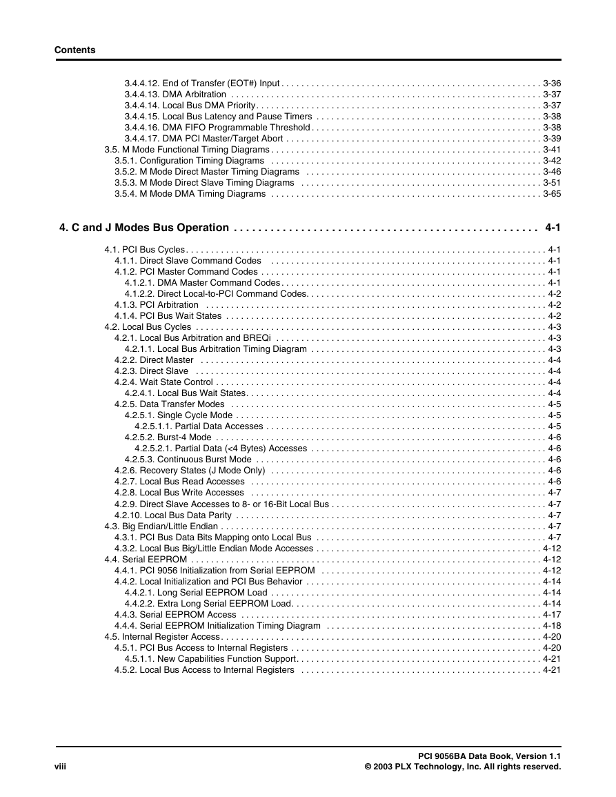
Contents 3.4.4.12. End of Transfer (EOT#) Input . . . . . . . . . . . . . . . . . . . . . . . . . . . . . . . . . . . . . . . . . . . . . . . . . . . . 3-36 3.4.4.13. DMA Arbitration . . . . . . . . . . . . . . . . . . . . . . . . . . . . . . . . . . . . . . . . . . . . . . . . . . . . . . . . . . . . . . 3-37 3.4.4.14. Local Bus DMA Priority. . . . . . . . . . . . . . . . . . . . . . . . . . . . . . . . . . . . . . . . . . . . . . . . . . . . . . . . . 3-37 3.4.4.15. Local Bus Latency and Pause Timers . . . . . . . . . . . . . . . . . . . . . . . . . . . . . . . . . . . . . . . . . . . . . 3-38 3.4.4.16. DMA FIFO Programmable Threshold . . . . . . . . . . . . . . . . . . . . . . . . . . . . . . . . . . . . . . . . . . . . . . 3-38 3.4.4.17. DMA PCI Master/Target Abort . . . . . . . . . . . . . . . . . . . . . . . . . . . . . . . . . . . . . . . . . . . . . . . . . . . 3-39 3.5. M Mode Functional Timing Diagrams . . . . . . . . . . . . . . . . . . . . . . . . . . . . . . . . . . . . . . . . . . . . . . . . . . . . . . 3-41 3.5.1. Configuration Timing Diagrams . . . . . . . . . . . . . . . . . . . . . . . . . . . . . . . . . . . . . . . . . . . . . . . . . . . . . . 3-42 3.5.2. M Mode Direct Master Timing Diagrams . . . . . . . . . . . . . . . . . . . . . . . . . . . . . . . . . . . . . . . . . . . . . . . 3-46 3.5.3. M Mode Direct Slave Timing Diagrams . . . . . . . . . . . . . . . . . . . . . . . . . . . . . . . . . . . . . . . . . . . . . . . . 3-51 3.5.4. M Mode DMA Timing Diagrams . . . . . . . . . . . . . . . . . . . . . . . . . . . . . . . . . . . . . . . . . . . . . . . . . . . . . . 3-65 4. C and J Modes Bus Operation . . . . . . . . . . . . . . . . . . . . . . . . . . . . . . . . . . . . . . . . . . . . . . . . . . 4-1 4.1. PCI Bus Cycles. . . . . . . . . . . . . . . . . . . . . . . . . . . . . . . . . . . . . . . . . . . . . . . . . . . . . . . . . . . . . . . . . . . . . . . . 4-1 4.1.1. Direct Slave Command Codes . . . . . . . . . . . . . . . . . . . . . . . . . . . . . . . . . . . . . . . . . . . . . . . . . . . . . . . 4-1 4.1.2. PCI Master Command Codes . . . . . . . . . . . . . . . . . . . . . . . . . . . . . . . . . . . . . . . . . . . . . . . . . . . . . . . . . 4-1 4.1.2.1. DMA Master Command Codes. . . . . . . . . . . . . . . . . . . . . . . . . . . . . . . . . . . . . . . . . . . . . . . . . . . . . 4-1 4.1.2.2. Direct Local-to-PCI Command Codes. . . . . . . . . . . . . . . . . . . . . . . . . . . . . . . . . . . . . . . . . . . . . . . . 4-2 4.1.3. PCI Arbitration . . . . . . . . . . . . . . . . . . . . . . . . . . . . . . . . . . . . . . . . . . . . . . . . . . . . . . . . . . . . . . . . . . . . 4-2 4.1.4. PCI Bus Wait States . . . . . . . . . . . . . . . . . . . . . . . . . . . . . . . . . . . . . . . . . . . . . . . . . . . . . . . . . . . . . . . . 4-2 4.2. Local Bus Cycles . . . . . . . . . . . . . . . . . . . . . . . . . . . . . . . . . . . . . . . . . . . . . . . . . . . . . . . . . . . . . . . . . . . . . . 4-3 4.2.1. Local Bus Arbitration and BREQi . . . . . . . . . . . . . . . . . . . . . . . . . . . . . . . . . . . . . . . . . . . . . . . . . . . . . . 4-3 4.2.1.1. Local Bus Arbitration Timing Diagram . . . . . . . . . . . . . . . . . . . . . . . . . . . . . . . . . . . . . . . . . . . . . . . 4-3 4.2.2. Direct Master . . . . . . . . . . . . . . . . . . . . . . . . . . . . . . . . . . . . . . . . . . . . . . . . . . . . . . . . . . . . . . . . . . . . . 4-4 4.2.3. Direct Slave . . . . . . . . . . . . . . . . . . . . . . . . . . . . . . . . . . . . . . . . . . . . . . . . . . . . . . . . . . . . . . . . . . . . . . 4-4 4.2.4. Wait State Control . . . . . . . . . . . . . . . . . . . . . . . . . . . . . . . . . . . . . . . . . . . . . . . . . . . . . . . . . . . . . . . . . . 4-4 4.2.4.1. Local Bus Wait States. . . . . . . . . . . . . . . . . . . . . . . . . . . . . . . . . . . . . . . . . . . . . . . . . . . . . . . . . . . . 4-4 4.2.5. Data Transfer Modes . . . . . . . . . . . . . . . . . . . . . . . . . . . . . . . . . . . . . . . . . . . . . . . . . . . . . . . . . . . . . . . 4-5 4.2.5.1. Single Cycle Mode . . . . . . . . . . . . . . . . . . . . . . . . . . . . . . . . . . . . . . . . . . . . . . . . . . . . . . . . . . . . . . 4-5 4.2.5.1.1. Partial Data Accesses . . . . . . . . . . . . . . . . . . . . . . . . . . . . . . . . . . . . . . . . . . . . . . . . . . . . . . . . 4-5 4.2.5.2. Burst-4 Mode . . . . . . . . . . . . . . . . . . . . . . . . . . . . . . . . . . . . . . . . . . . . . . . . . . . . . . . . . . . . . . . . . . 4-6 4.2.5.2.1. Partial Data (<4 Bytes) Accesses . . . . . . . . . . . . . . . . . . . . . . . . . . . . . . . . . . . . . . . . . . . . . . . 4-6 4.2.5.3. Continuous Burst Mode . . . . . . . . . . . . . . . . . . . . . . . . . . . . . . . . . . . . . . . . . . . . . . . . . . . . . . . . . . 4-6 4.2.6. Recovery States (J Mode Only) . . . . . . . . . . . . . . . . . . . . . . . . . . . . . . . . . . . . . . . . . . . . . . . . . . . . . . . 4-6 4.2.7. Local Bus Read Accesses . . . . . . . . . . . . . . . . . . . . . . . . . . . . . . . . . . . . . . . . . . . . . . . . . . . . . . . . . . . 4-6 4.2.8. Local Bus Write Accesses . . . . . . . . . . . . . . . . . . . . . . . . . . . . . . . . . . . . . . . . . . . . . . . . . . . . . . . . . . . 4-7 4.2.9. Direct Slave Accesses to 8- or 16-Bit Local Bus . . . . . . . . . . . . . . . . . . . . . . . . . . . . . . . . . . . . . . . . . . . 4-7 4.2.10. Local Bus Data Parity . . . . . . . . . . . . . . . . . . . . . . . . . . . . . . . . . . . . . . . . . . . . . . . . . . . . . . . . . . . . . . 4-7 4.3. Big Endian/Little Endian . . . . . . . . . . . . . . . . . . . . . . . . . . . . . . . . . . . . . . . . . . . . . . . . . . . . . . . . . . . . . . . . . 4-7 4.3.1. PCI Bus Data Bits Mapping onto Local Bus . . . . . . . . . . . . . . . . . . . . . . . . . . . . . . . . . . . . . . . . . . . . . . 4-7 4.3.2. Local Bus Big/Little Endian Mode Accesses . . . . . . . . . . . . . . . . . . . . . . . . . . . . . . . . . . . . . . . . . . . . . 4-12 4.4. Serial EEPROM . . . . . . . . . . . . . . . . . . . . . . . . . . . . . . . . . . . . . . . . . . . . . . . . . . . . . . . . . . . . . . . . . . . . . . 4-12 4.4.1. PCI 9056 Initialization from Serial EEPROM . . . . . . . . . . . . . . . . . . . . . . . . . . . . . . . . . . . . . . . . . . . . 4-12 4.4.2. Local Initialization and PCI Bus Behavior . . . . . . . . . . . . . . . . . . . . . . . . . . . . . . . . . . . . . . . . . . . . . . . 4-14 4.4.2.1. Long Serial EEPROM Load . . . . . . . . . . . . . . . . . . . . . . . . . . . . . . . . . . . . . . . . . . . . . . . . . . . . . . 4-14 4.4.2.2. Extra Long Serial EEPROM Load. . . . . . . . . . . . . . . . . . . . . . . . . . . . . . . . . . . . . . . . . . . . . . . . . . 4-14 4.4.3. Serial EEPROM Access . . . . . . . . . . . . . . . . . . . . . . . . . . . . . . . . . . . . . . . . . . . . . . . . . . . . . . . . . . . . 4-17 4.4.4. Serial EEPROM Initialization Timing Diagram . . . . . . . . . . . . . . . . . . . . . . . . . . . . . . . . . . . . . . . . . . . 4-18 4.5. Internal Register Access. . . . . . . . . . . . . . . . . . . . . . . . . . . . . . . . . . . . . . . . . . . . . . . . . . . . . . . . . . . . . . . . 4-20 4.5.1. PCI Bus Access to Internal Registers . . . . . . . . . . . . . . . . . . . . . . . . . . . . . . . . . . . . . . . . . . . . . . . . . . 4-20 4.5.1.1. New Capabilities Function Support. . . . . . . . . . . . . . . . . . . . . . . . . . . . . . . . . . . . . . . . . . . . . . . . . 4-21 4.5.2. Local Bus Access to Internal Registers . . . . . . . . . . . . . . . . . . . . . . . . . . . . . . . . . . . . . . . . . . . . . . . . 4-21 viii PCI 9056BA Data Book, Version 1.1 © 2003 PLX Technology, Inc. All rights reserved.
分享到:
收藏